¶ Issue Description
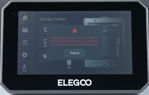
The following error message appears on the touchscreen:
Printhead anomaly detected. Please troubleshoot the connections between the mainboard and printhead board.
¶ Tools Required for Troubleshooting
- A 1.5 mm Allen key
- A 2.0 mm Allen key
- A multimeter with diode-test mode
- A Phillips-head screwdriver required for some printer versions
¶ Troubleshooting Steps
¶ Check the Printhead Communication Cable for an Intermittent Connection
- Power on the printer.
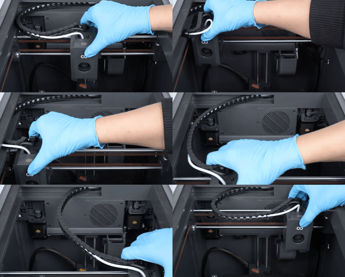
- Gently move the printhead and check whether the error message appears on the touchscreen.
-
If moving the printhead triggers the error, the printhead communication cable may have a loose or intermittent connection. Proceed with further troubleshooting by following
Check the Printhead-Side Cable Connector. -
If moving the printhead does not trigger the error, continue with the following steps.Proceed with further troubleshooting by following
Check the Mainboard-Side Cable Connector.
¶ Check the Printhead-Side Cable Connector
- Power off the printer and unplug the power cord.
- Check whether the wires near the printhead connector are damaged and confirm that the connector is fully seated.
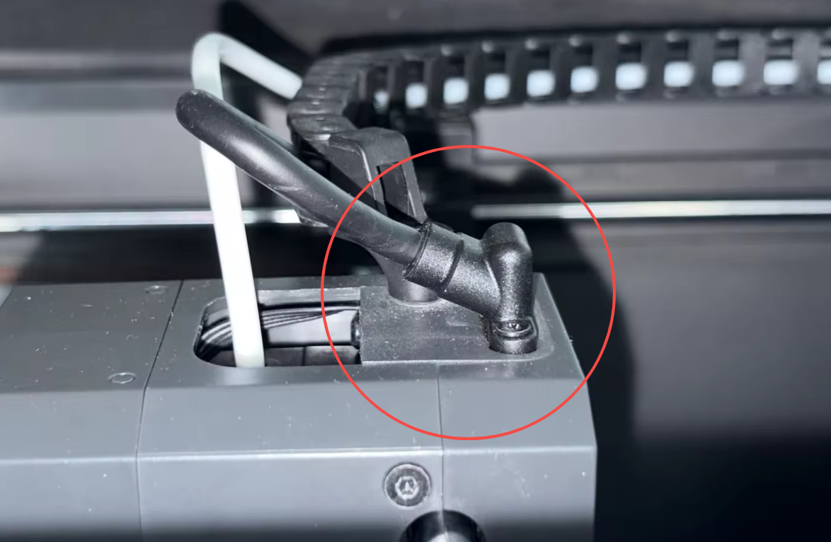
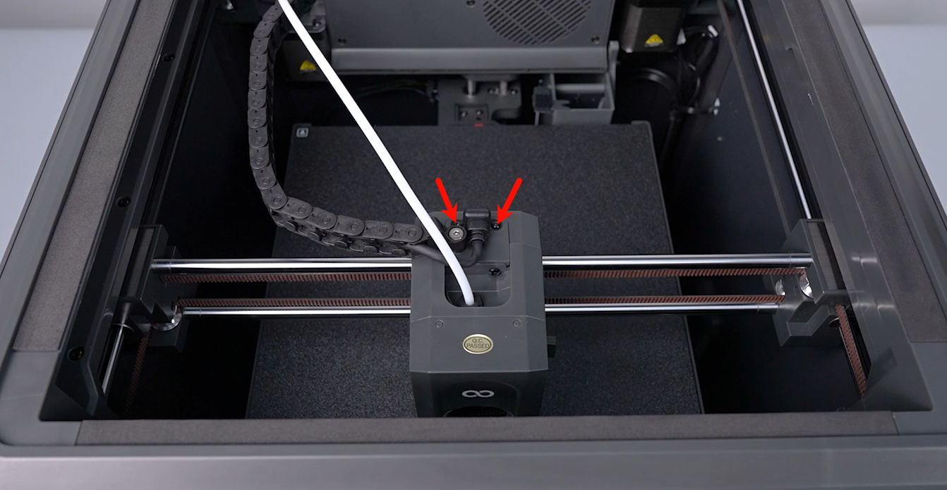
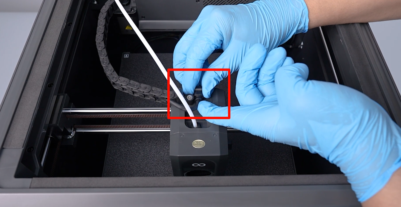
- Use a 1.5 mm Allen key to loosen the two screws securing the printhead communication cable connector.
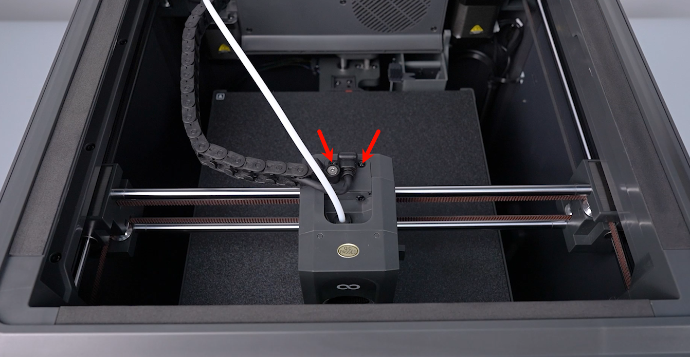
- Unplug and reconnect the communication cable. Inspect the cable and connector for visible damage.
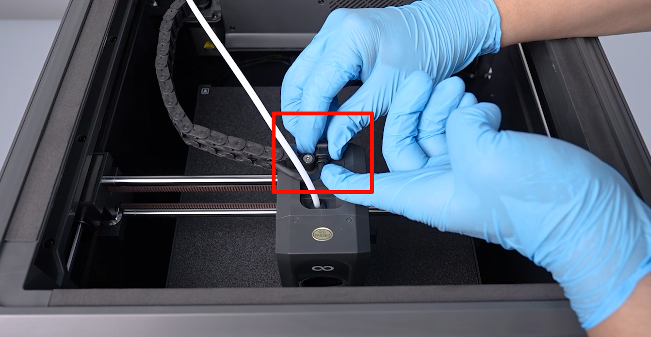
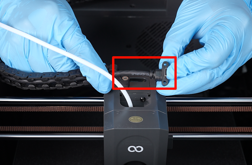
- If the cable or its connector is damaged, replace the printhead communication cable. See How to Replace the Connection Cable of the Print Head.
- If no damage is found, continue with the following steps.
¶ Check the Mainboard-Side Cable Connector
- Make sure the printer is powered off and the power cord is unplugged.
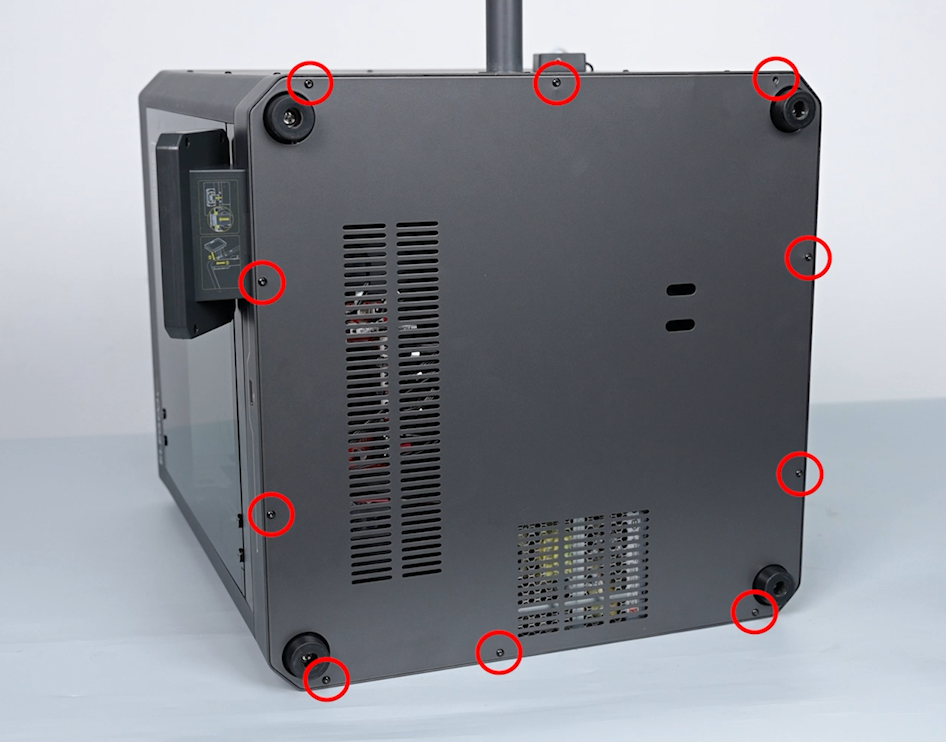
- Use a 2.0 mm Allen key to remove the ten screws securing the bottom cover, and then remove the bottom cover.
- Unplug and reconnect the printhead communication cable at the mainboard connector.
- Inspect the cable and connector for visible damage.
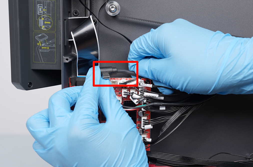
- If the cable or its connector is damaged, replace the printhead communication cable.
- If no damage is found, reconnect the cable securely.
- Power on the printer and check whether the error still occurs.
¶ Measure the Diode-Mode Reading of the Printhead PCB
This procedure requires experience using a multimeter. If you do not have a multimeter and the issue remains unresolved, skip the electrical measurements and provide the information requested at the end of this article to Technical Support.
- Power off the printer and unplug the power cord.
- Use a 1.5 mm Allen key to loosen the two screws securing the printhead cable connector. (Some printer versions use Phillips-head screws instead.)
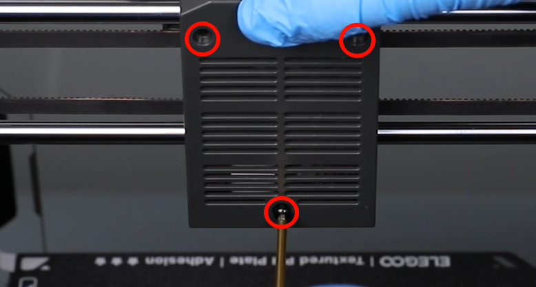
- Use a 2.0 mm Allen key to remove the three screws securing the printhead rear cover, and then remove the cover.
- Disconnect the printhead communication cable.
- Set the multimeter to diode-test mode.
- Measure the diode-mode reading between the connector terminal and the corresponding component pin shown in the image. The normal reading should be approximately
0.700 V.
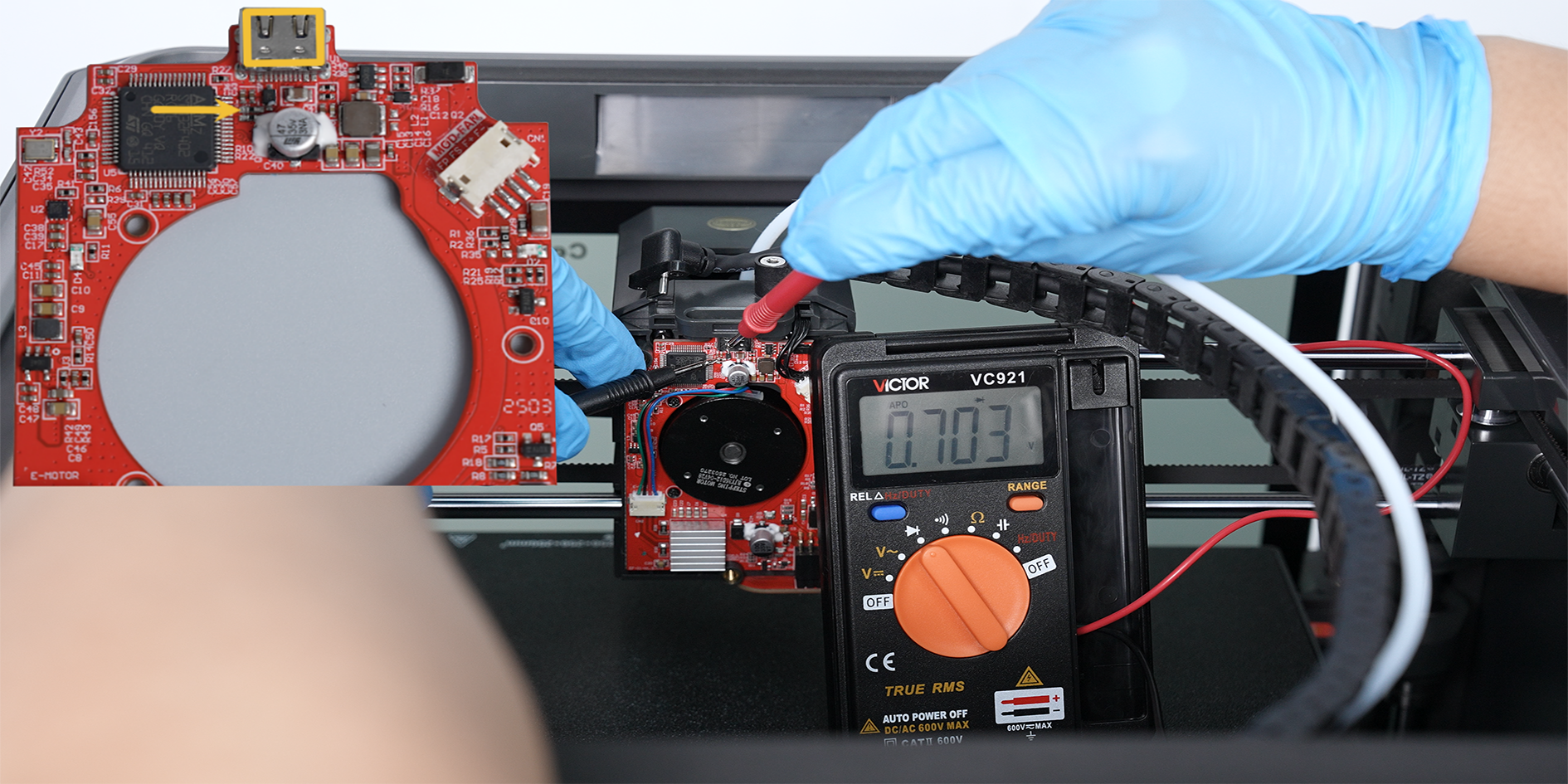
Probe placement:
- Place the red probe on the specified terminal inside the communication cable connector.
- Place the black probe on the corresponding electronic-component pin shown in the image.
The printer must remain powered off and unplugged during the measurement. Never perform a diode-mode or resistance measurement on an energized circuit.
- If the measured value is significantly different from approximately
0.700 V, the printhead PCB may be faulty. Replace the printhead PCB and retest the printer.
See How to Replace the Print Head PCB.
- If the reading is normal, continue with the following steps.
¶ Measure the Diode-Mode Reading at the Mainboard Connector
- Confirm that the printer is powered off and the power cord is unplugged.
- If the bottom cover has been reinstalled, use a 2.0 mm Allen key to remove the ten screws securing it, and then remove the bottom cover.
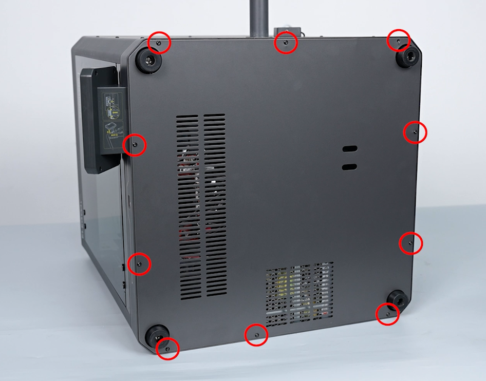
- Disconnect the printhead communication cable from the mainboard.
- Set the multimeter to diode-test mode.
- Measure the diode-mode reading between the mainboard connector terminal and the corresponding component pin shown in the images. The normal reading should be approximately
0.700 V.
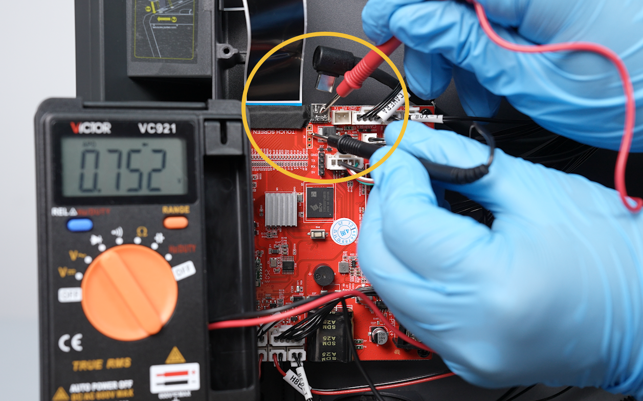
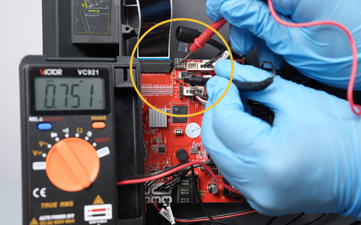
Probe placement:
- Place the red probe on the specified terminal inside the mainboard-side connector.
- Place the black probe on the corresponding electronic-component pin shown in the image.
The printer must remain powered off and unplugged during the measurement. Never perform a diode-mode or resistance measurement on an energized circuit.
- If the measured value is significantly different from approximately
0.700 V, the mainboard may be faulty. Replace the mainboard and retest the printer.
See How to Replace the Motherboard.
- If the reading is normal but the error remains, contact Technical Support.
¶ Still Having Issues?
Please contact technical support Email: 3dp@elegoo.comand provide the following information:
- A video showing how the error occurs.
- Confirmation of the test result: Does gently moving the printhead trigger the error?
- Photos of the connectors at both ends of the printhead communication cable.
- The diode-mode measurement results for the printhead PCB and mainboard. If you do not have a multimeter, you do not need to provide this information.
- Printer firmware version (Skip this item if the printer cannot access the menu.)
- The printer serial number (The code printed on the white label near the power button).
¶ Help Us Improve
If you have any suggestions for improving the wiki, please submit them through the ELEGOO Official Feedback Channel.