¶ PhotoCell
¶ Overview
In this tutorial, you will learn how to measure light intensity using an Analog Input. You will use the level of light to control the number of LEDs to be lit.
¶ Component Required:
(2) x 400 tie-points breadboard
(8) x leds
(8) x 220 ohm resistors
(1) x 1k ohm resistor
(1) x 74hc595 IC
(1) x Photoresistor (Photocell)
(20) x M-M wires (Male to Male jumper wires)
¶ Component Introduction
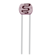
PHOTOCELL:
The photocell used, is a type call a light dependant resistor. Also known as an LDR. As the name suggests, these components act just like a resistor, except that the resistance changes in response to how much light is falling on them.
This one has a resistance of about 50 kΩ in near darkness and 500 Ω in bright light.
To convert this varying value of resistance into something we can measure on an ESP32 board's analog input, it needs to be converted into a voltage.
The simplest way to do that is to combine it with a fixed resistor.
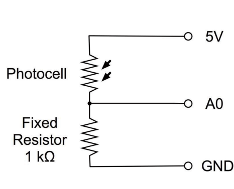
Load up the sketch given in the next section and try covering the photocell with your finger, and then holding it near a light source.
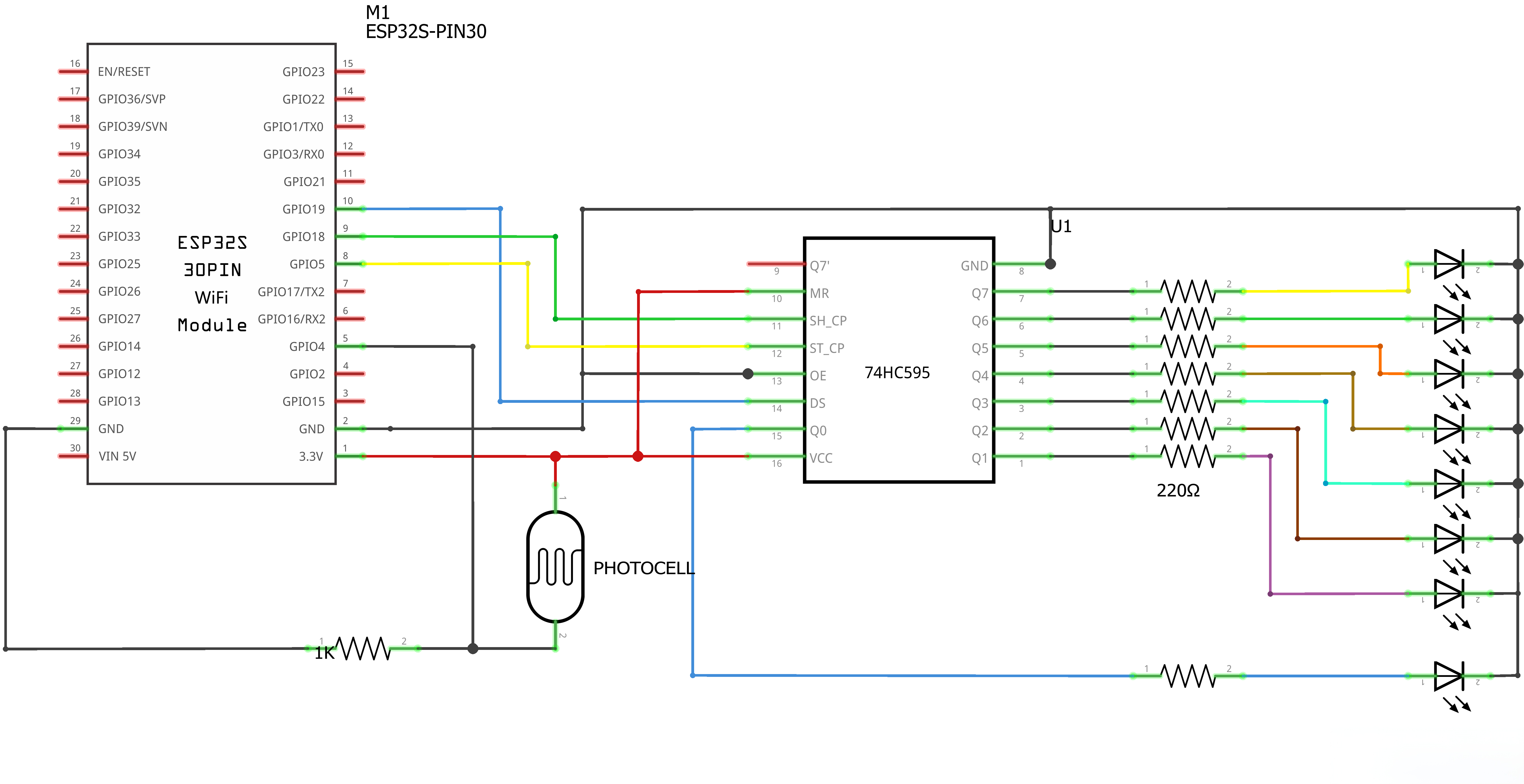
¶ Connection Schematic
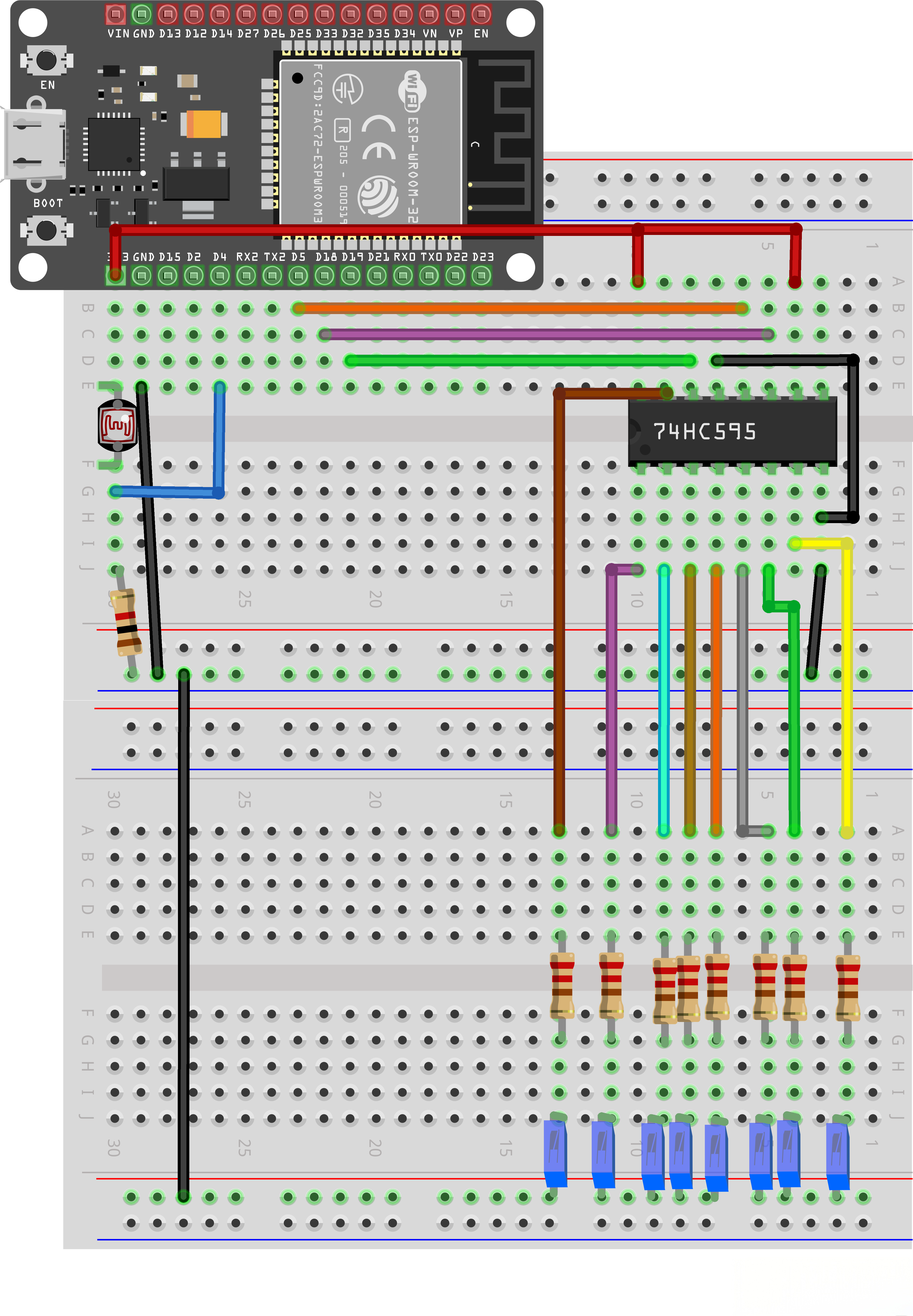
¶ Wiring diagram
¶ Code
You can click the blue text link to download the program file to your local device, and double-click the file to open it after the download is complete. Please note: Before opening the file, ensure that you have installed the Arduino IDE development environment and completed the installation of relevant components such as the board support package and driver corresponding to the ESP32 development board. If you have any questions about this operation process, you can refer to the "part 1" chapter of the document for detailed guidance.
With this code, the ESP32 reads the light intensity from a photoresistor, maps the value to control the number of LEDs lit, and uses a 74HC595 shift register to control the LEDs.
Click the Serial Monitor button to turn on the serial monitor. The basics about the serial monitor are introduced in details in tutorial 4 in part 2.
int lightPin = 4;
int latchPin = 5;
int clockPin = 18;
int dataPin = 19;int leds = 0;
Pin Definitions:
int lightPin = 4;:Analog input pin for light sensor (photoresistor) connected to ESP32 ADC1 channelint latchPin = 5;:Connected to ST_CP of 74HC595 (latch pin)int clockPin = 18;:Connected to SH_CP of 74HC595 (clock pin)int dataPin = 19;:Connected to DS of 74HC595 (data pin)int leds = 0;:Variable to store LED state (bit pattern)
void setup()
{
pinMode(latchPin, OUTPUT);
pinMode(dataPin, OUTPUT);
pinMode(clockPin, OUTPUT);
}
Setup Function:
pinMode(latchPin, OUTPUT);:Sets latchPin as outputpinMode(dataPin, OUTPUT);:Sets dataPin as outputpinMode(clockPin, OUTPUT);:Sets clockPin as output
void updateShiftRegister()
{
digitalWrite(latchPin, LOW);
shiftOut(dataPin, clockPin, LSBFIRST, leds);
digitalWrite(latchPin, HIGH);
}
Update Shift Register Function:
void updateShiftRegister():Updates the 74HC595 shift register with the current LED statedigitalWrite(latchPin, LOW);:Sets latch pin low to prepare for data transfershiftOut(dataPin, clockPin, LSBFIRST, leds);:Shifts out the LED state, least significant bit firstdigitalWrite(latchPin, HIGH);:Sets latch pin high to lock the data into the 74HC595 outputs
void loop()
{
int reading = analogRead(lightPin);int numLEDSLit = map(reading, 0, 2023, 0, 8);
if (numLEDSLit > 8) numLEDSLit = 8;
leds = 0; // no LEDs lit to start
for (int i = 0; i < numLEDSLit; i++)
{
leds = leds + (1 << i); // sets the i'th bit
}
updateShiftRegister();
}
Loop Function:
int reading = analogRead(lightPin);:Reads the analog value from the light sensorint numLEDSLit = map(reading, 0, 2023, 0, 8);:Maps the light sensor value (0-2023) to the number of LEDs to light (0-8)if (numLEDSLit > 8) numLEDSLit = 8;:Ensures no more than 8 LEDs are litleds = 0;:Resets LED state to all offfor (int i = 0; i < numLEDSLit; i++) { leds = leds + (1 << i); }:Sets the appropriate bits to light the desired number of LEDs (uses bitwise shift to set each bit)updateShiftRegister();:Updates the shift register to display the new LED state
¶ Troubleshooting
- No LEDs Lighting:Check all wiring connections and ensure 74HC595 is properly powered
- LEDs Not Responding to Light:Verify light sensor connections and adjust the mapping range if needed
- Erratic LED Behavior:Ensure proper grounding and consider adding decoupling capacitors
- No Response:Check ESP32 pin assignments and ensure correct board selection in Arduino IDE