¶ 74HC595 And Segment Display
¶ Overview
In this tutorial ,we will use the 74HC595 shift register to control the segment display. The segment display will show number from 0-9.
¶ Component Required:

(1) x Elegoo ESP32
(1) x 400 tie-points breadboard
(1) x 74HC595 IC
(1) x 1 Digit 7-Segment Display
(8) x 220 Ω resistors
(26) x M-M wires (Male to Male jumper wires)
¶ Component Introduction
Seven segment display
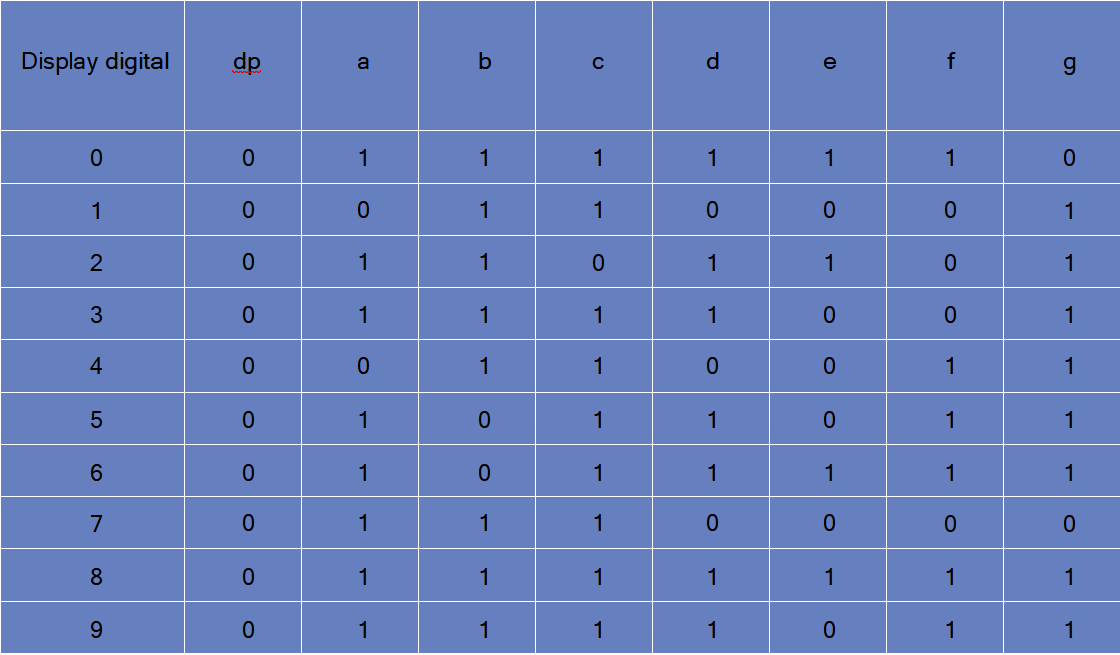
Below is the segment pin diagram.0-9 ten digits correspond with each segment are as follows (the following table applies common cathode seven segment
display device, if you are using a common anode, the table should be replaced every 1 0 (1->0,0->1).
0 should all replaced by 1
1 should all replaced by 0:
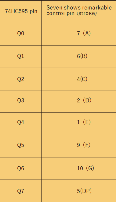
The following table shows the seven-segment display 74HC595 pin correspondence table:
Step one: Connect 74HC595
.png)
First, the wiring is connected to power and ground:
VCC (pin 16) and MR (pin 10) connected to 3.3V
GND (pin 8) and OE (pin 13) to ground
Connection DS, ST_CP and SH_CP pin:
DS (pin 14) connected to ESP32 board GPIO D5
ST_CP (pin 12, latch pin) connected to ESP32 board GPIO D18
ST_CP (pin 11, clock pin) connected to ESP32 board GPIO D19
Step two: Connect the segment display
The seven-segment display 3 and 8 pins to the ESP32 boards GND. (This example uses the common cathode, if you use the common anode, please connect 3 and 8 pins pin to ESP32 board + 3.3V)
According to the table above, connect the 74HC595 Q0 ~ Q7 to seven-segment display corresponding pin (A ~ G and DP), and then each lead in a 220Ω resistor in series..
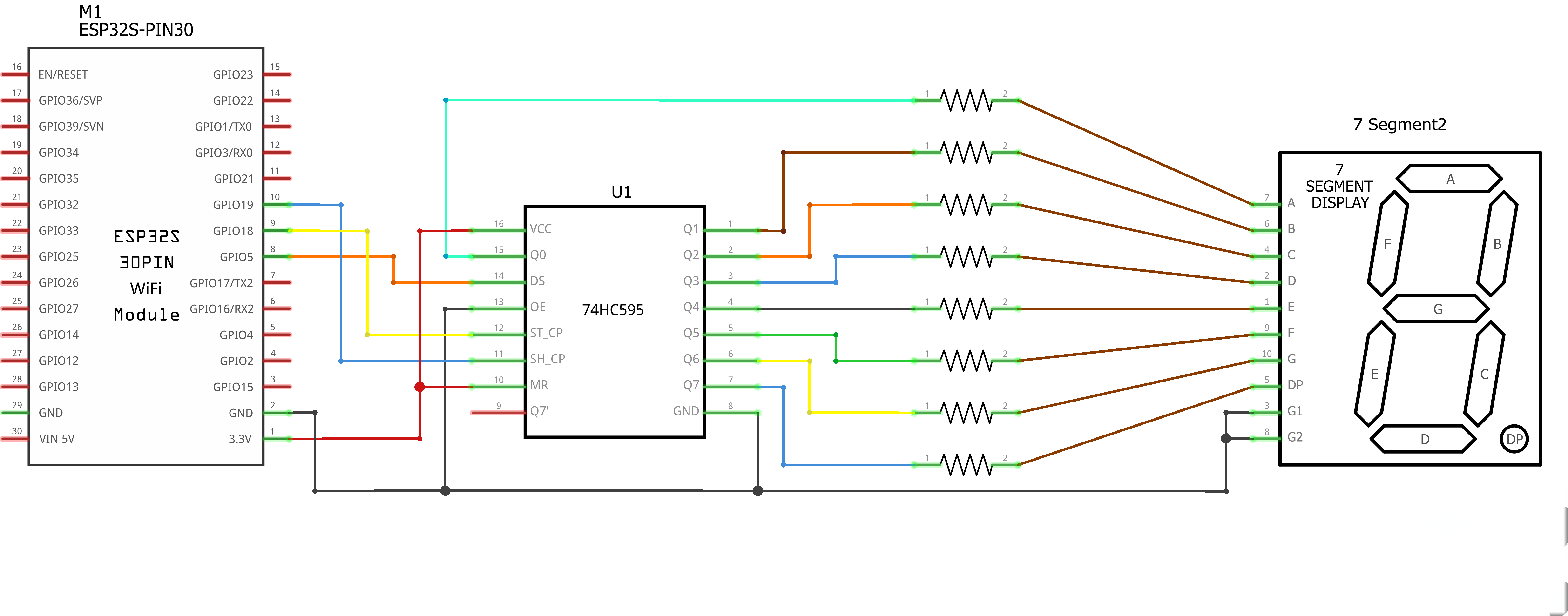
¶ Connection Schematic
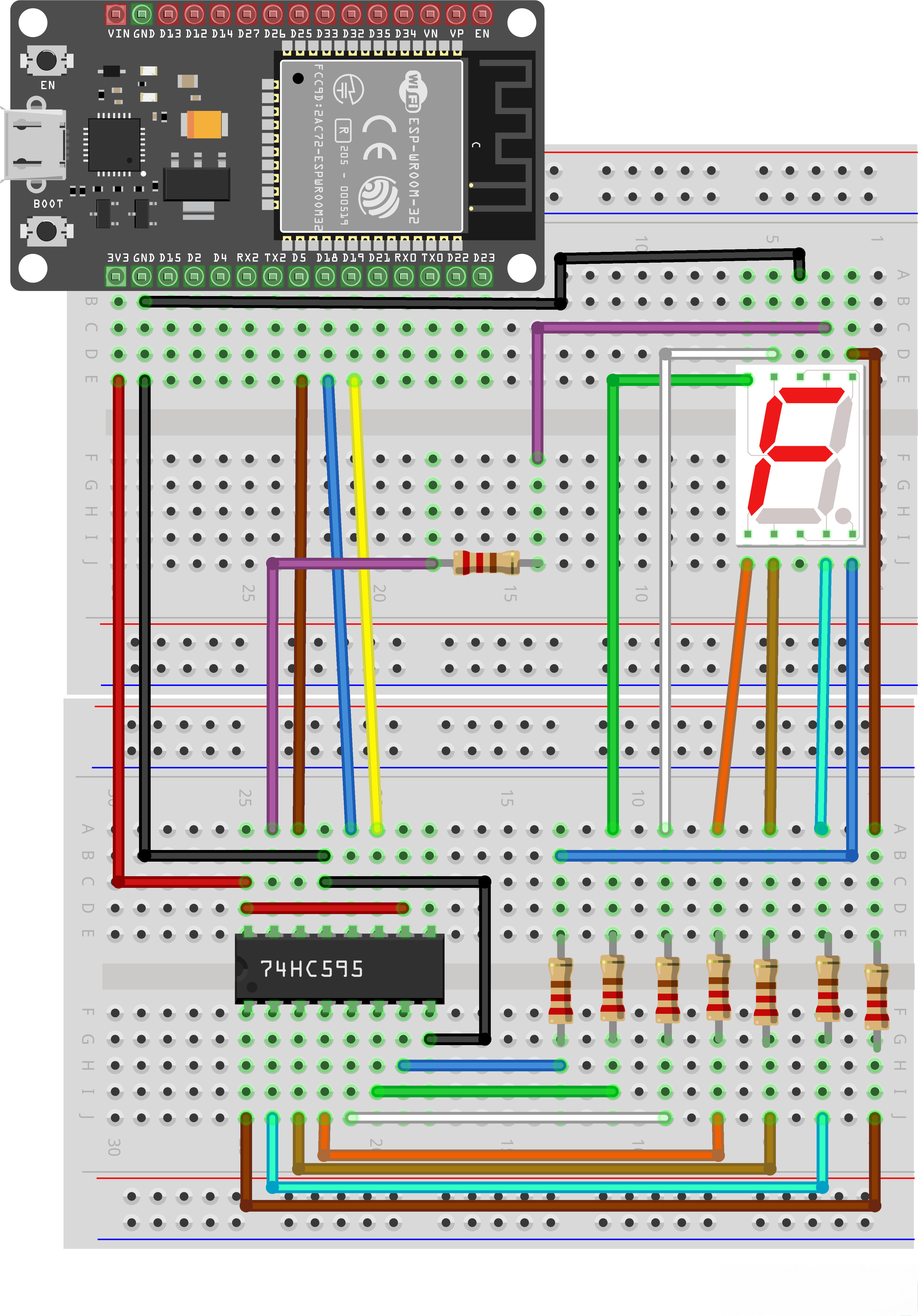
¶ Wiring diagram
¶ Code
You can click the blue text link to download the program file to your local device, and double-click the file to open it after the download is complete. Please note: Before opening the file, ensure that you have installed the Arduino IDE development environment and completed the installation of relevant components such as the board support package and driver corresponding to the ESP32 development board. If you have any questions about this operation process, you can refer to the "part 1" chapter of the document for detailed guidance.
With this code, the ESP32 controls a 7-segment LED display through a 74HC595 shift register, counting down from 9 to 0 repeatedly with a 1-second delay between each number.
Click the Serial Monitor button to turn on the serial monitor. The basics about the serial monitor are introduced in details in tutorial 4 in part 2.
// define the LED digit patterns, from 0 - 9
// 1 = LED on, 0 = LED off, in this order:
// 74HC595 pin Q0,Q1,Q2,Q3,Q4,Q5,Q6,Q7
// Mapping to a,b,c,d,e,f,g of Seven-Segment LED
byte seven_seg_digits[10] = { B11111100, // = 0
B01100000, // = 1
B11011010, // = 2
B11110010, // = 3
B01100110, // = 4
B10110110, // = 5
B10111110, // = 6
B11100000, // = 7
B11111110, // = 8
B11100110 // = 9
};
Seven-Segment Display Patterns:
byte seven_seg_digits[10]:Array storing bit patterns for digits 0-9- Each byte represents which segments to turn on (1) or off (0)
- Bit order: Q0-Q7 mapped to segments a-g of the 7-segment display
- Example:
B11111100for digit 0 turns on all segments except the decimal point
// connect to the ST_CP of 74HC595 (pin 3,latch pin)
int latchPin = 18;
// connect to the SH_CP of 74HC595 (pin 4, clock pin)
int clockPin = 19;
// connect to the DS of 74HC595 (pin 2)
int dataPin = 5;
74HC595 Shift Register Pins:
int latchPin = 18;:Connected to ST_CP (pin 3) of 74HC595, used to latch dataint clockPin = 19;:Connected to SH_CP (pin 4) of 74HC595, provides clock signalint dataPin = 5;:Connected to DS (pin 2) of 74HC595, sends serial data
void setup() {
// Set latchPin, clockPin, dataPin as output
pinMode(latchPin, OUTPUT);
pinMode(clockPin, OUTPUT);
pinMode(dataPin, OUTPUT);
}
Setup Function:
pinMode(latchPin, OUTPUT);:Sets latchPin as outputpinMode(clockPin, OUTPUT);:Sets clockPin as outputpinMode(dataPin, OUTPUT);:Sets dataPin as output
// display a number on the digital segment display
void sevenSegWrite(byte digit) {
// set the latchPin to low potential, before sending data
digitalWrite(latchPin, LOW);// the original data (bit pattern)
shiftOut(dataPin, clockPin, LSBFIRST, seven_seg_digits[digit]);// set the latchPin to high potential, after sending data
digitalWrite(latchPin, HIGH);
}
Seven-Segment Write Function:
void sevenSegWrite(byte digit):Writes a digit (0-9) to the 7-segment displaydigitalWrite(latchPin, LOW);:Sets latch pin low to prepare for data transfershiftOut(dataPin, clockPin, LSBFIRST, seven_seg_digits[digit]);:Shifts out the bit pattern for the specified digit, least significant bit firstdigitalWrite(latchPin, HIGH);:Sets latch pin high to lock the data into the 74HC595 outputs
void loop() {
// count from 9 to 0
for (byte digit = 10; digit > 0; --digit) {
delay(1000);
sevenSegWrite(digit - 1);
}
// sevenSegWrite(0); // test one
// delay(1000);
// // sevenSegWrite(1); // test two
// delay(1000);
// suspend 4 seconds
delay(3000);
}
Loop Function:
for (byte digit = 10; digit > 0; --digit) { ... }:Counts down from 9 to 0delay(1000);:Waits 1 second between each digitsevenSegWrite(digit - 1);:Displays the current digit (subtracting 1 because we start from 10)delay(3000);:Pauses for 3 seconds after completing the countdown
¶ Troubleshooting
- Display Not Working:Check all wiring connections and ensure 74HC595 is properly powered
- Incorrect Digits:Verify the segment mapping matches your display (you may need to adjust the bit patterns)
- Flickering Display:Ensure proper grounding and consider adding decoupling capacitors
- No Response:Check ESP32 pin assignments and ensure correct board selection in Arduino IDE