¶ Analog Joystick Module
¶ Overview
Analog joysticks are a great way to add some control in your projects.
In this tutorial we will learn how to use the analog joystick module.
¶ Component Required:
(1) x Joystick module
(2) x 400 Tie Points Breadboard
(5) x F-Mwires (FeMale to Male DuPont wires)
¶ Component Introduction
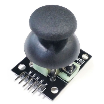
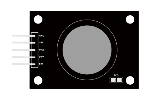
¶ Joystick
The module has 5 pins: VCC, Ground, X, Y, Key. Note that the labels on yours may be slightly different, depending on where you got the module from. The thumb stick is analog and should provide more accurate readings than simple ‘directional’ joysticks that use some forms of buttons, or mechanical switches. Additionally, you can press the joystick down (rather hard on mine) to activate a ‘press to select ’push- button.
We have to use analog Arduino pins to read the data from the X/Y pins, and a digital pin to read the button. The Key pin is connected to ground, when the joystick is pressed down, and is floating otherwise. To get stable readings from the Key /Select pin, it needs to be connected to VCC via a pull-up resistor.
The built in resistors on the Arduino digital pins can be used. For a tutorial on how to activate the pull-up resistors for Arduino pins, configured as inputs.For example: pinMode(SW_pin, INPUT);
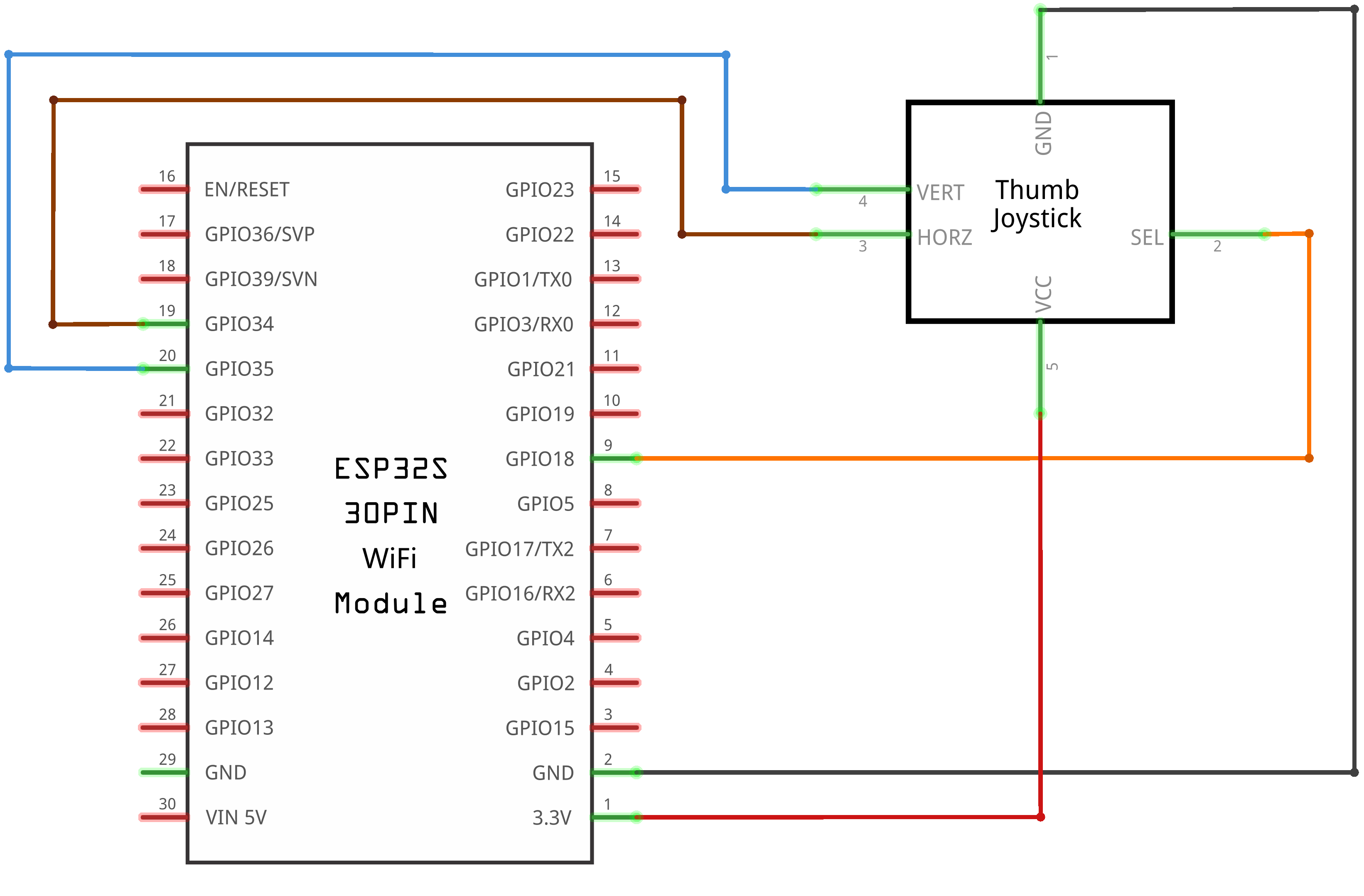
¶ Connection Schematic
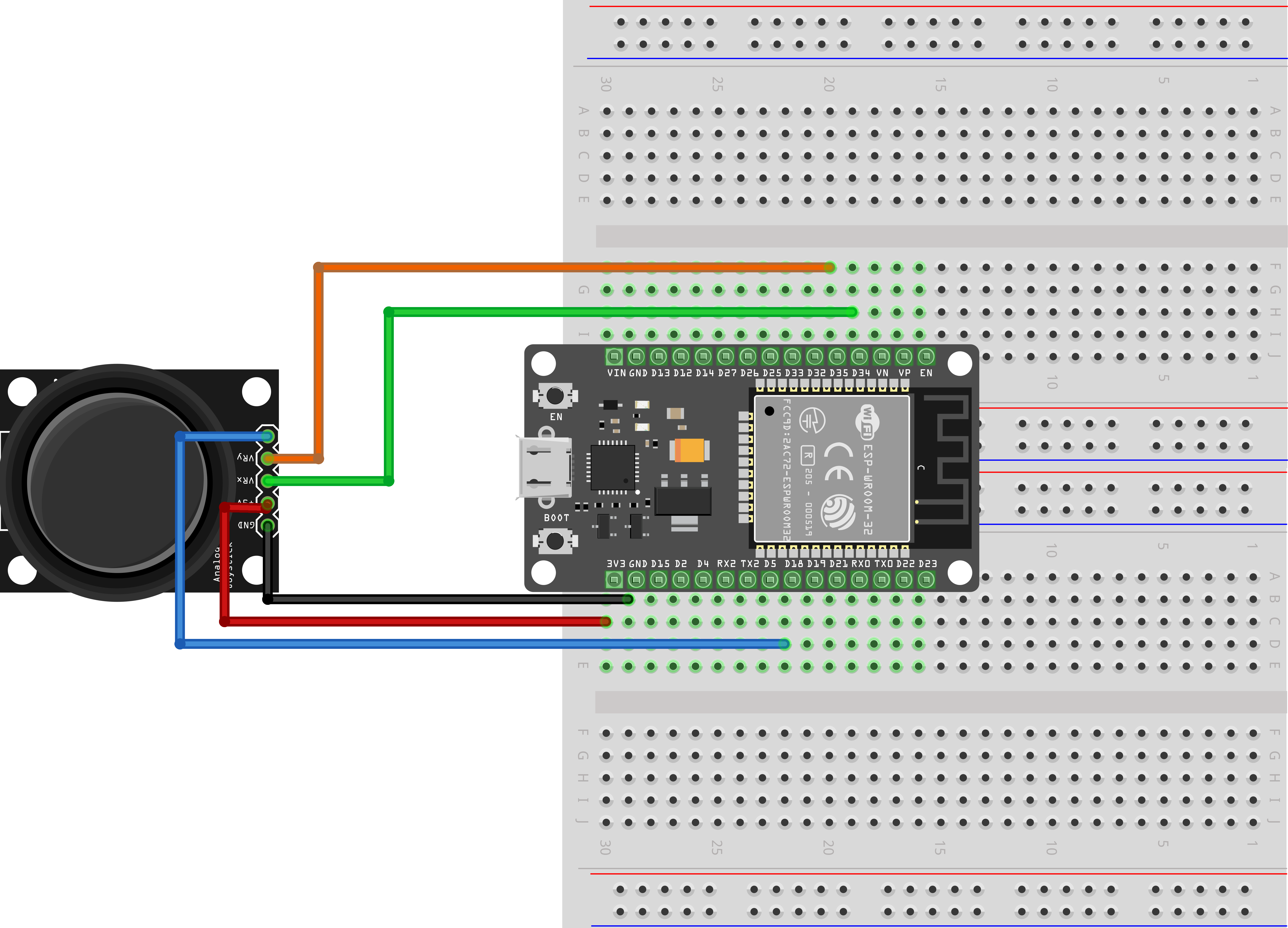
¶ Wiring diagram
¶ Code
You can click the blue text link to download the program file to your local device, and double-click the file to open it after the download is complete. Please note: Before opening the file, ensure that you have installed the Arduino IDE development environment and completed the installation of relevant components such as the board support package and driver corresponding to the ESP32 development board. If you have any questions about this operation process, you can refer to the "part 1" chapter of the document for detailed guidance.
const int SW_pin = 18; // digital pin connected to switch output
const int X_pin = 34; // analog pin connected to X output
const int Y_pin = 35; // analog pin connected to Y output
Pin Configuration:
const int SW_pin = 18: Defines the digital pin (18) connected to the joystick's switch outputconst int X_pin = 34: Defines the analog pin (34) connected to the joystick's X-axis outputconst int Y_pin = 35: Defines the analog pin (35) connected to the joystick's Y-axis output- Using
const intensures these values are fixed and uses minimal memory
void setup() {
pinMode(SW_pin, INPUT);
digitalWrite(SW_pin, HIGH);
Serial.begin(9600);
}
setup() Function:Initializes the system.
pinMode(SW_pin, INPUT): Configures the switch pin as an inputdigitalWrite(SW_pin, HIGH): Enables internal pull-up resistor for the switch inputSerial.begin(9600): Initializes the serial communication with a baud rate of 9600 to allow communication with the computer's serial monitor
void loop() {
Serial.print("Switch: ");
Serial.print(digitalRead(SW_pin));
Serial.print("\n");
Serial.print("X-axis: ");
Serial.print(analogRead(X_pin));
Serial.print("\n");
Serial.print("Y-axis: ");
Serial.println(analogRead(Y_pin));
Serial.print("\n\n");
delay(1000);
}
loop() Function:The main loop that continuously reads and displays joystick data.
digitalRead(SW_pin): Reads the digital value from the joystick switch (0 for pressed, 1 for released)analogRead(X_pin): Reads the analog value from the X-axis potentiometer (0-4095 for ESP32)analogRead(Y_pin): Reads the analog value from the Y-axis potentiometer (0-4095 for ESP32)Serial.print(): Prints the sensor values to the serial monitordelay(1000): Pauses the loop for 1000 milliseconds (1 second) between readings
Digital Input with Pull-up Resistor:
The switch pin is configured with INPUT mode and internal pull-up resistor enabled (digitalWrite(SW_pin, HIGH)). This means:
- When the switch is not pressed, the pin reads HIGH (1)
- When the switch is pressed, the pin reads LOW (0)
- This configuration simplifies wiring by eliminating the need for external pull-up resistors
DigitalWrite vs AnalogWrite:
These are two fundamental I/O functions in Arduino/ESP32 programming:
digitalWrite() Function:
- Used to set a digital pin to either HIGH (5V on ESP32) or LOW (0V)
- Syntax:
digitalWrite(pin, value) pin: The digital pin number to write tovalue: Either HIGH (1) or LOW (0)- Common uses: Controlling LEDs, relays, or other digital devices
- In this code, it's used to enable the internal pull-up resistor for the switch pin
analogWrite() Function:
- Used to generate a Pulse Width Modulation (PWM) signal on a pin
- Syntax:
analogWrite(pin, value) pin: The PWM-capable pin to write tovalue: A value between 0 (0% duty cycle) and 255 (100% duty cycle)- Generates a square wave with variable duty cycle to simulate analog output
- Common uses: Dimming LEDs, controlling motor speed, adjusting brightness
- Note: On ESP32, you can also use
ledcWrite()for more precise PWM control
Key Differences:
- Output Type: digitalWrite produces discrete HIGH/LOW signals; analogWrite produces variable duty cycle PWM signals
- Value Range: digitalWrite accepts 0/1; analogWrite accepts 0-255
- Pin Compatibility: Most pins support digitalWrite; only specific pins support analogWrite
- Functionality: digitalWrite controls on/off states; analogWrite controls intensity/level
- Use Cases: digitalWrite for digital devices; analogWrite for analog-like control
Analog Input on ESP32:
ESP32 microcontrollers have 18 analog-to-digital converter (ADC) channels with 12-bit resolution:
- This means analog values are converted to digital values ranging from 0 to 4095
- Pins 34 and 35 are ADC1 channels, which are suitable for analog input applications
- The X and Y axis readings represent the position of the joystick potentiometers
Joystick Module Operation:
A typical joystick module includes:
- Two potentiometers for X and Y axis control
- A push button (switch) that activates when the joystick is pressed
- Analog outputs for X and Y position
- Digital output for switch status
When the joystick is moved, it changes the resistance of the potentiometers, resulting in varying voltage outputs that can be read by the ESP32's analog inputs.