¶ Digital Inputs
¶ Overview
In this lesson, you will learn to use push buttons with digital inputs to turn an LED on and off. Pressing the button will turn the LED on; pressing the other button will turn the LED off.
¶ Component Required:
(1) x Elegoo UNO
(1) x 830 Tie-points Breadboard
(1) x 5mm red LED
(1) x 220 Ω resistor
(2) x push switches
(7) x M-M wires (Male to Male jumper wires)
¶ Component Introduction
¶ PUSH SWITCHES:
Switches are really simple components. When you press a button or flip a lever, they connect two contacts together so that electricity can flow through them.The little tactile switches that are used in this lesson have four connections, which can be a little confusing.
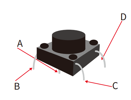
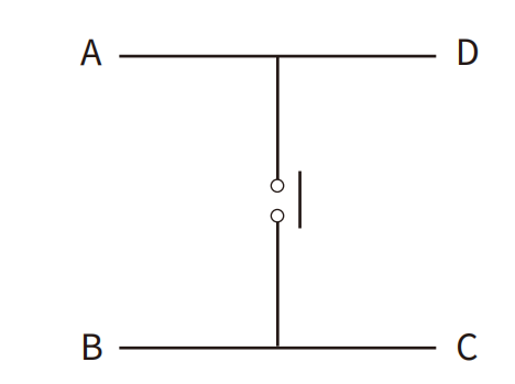
Actually, there are only really two electrical connections. Inside the switch package, pins B and C are connected together, as are A and D.
¶ Connection Schematic
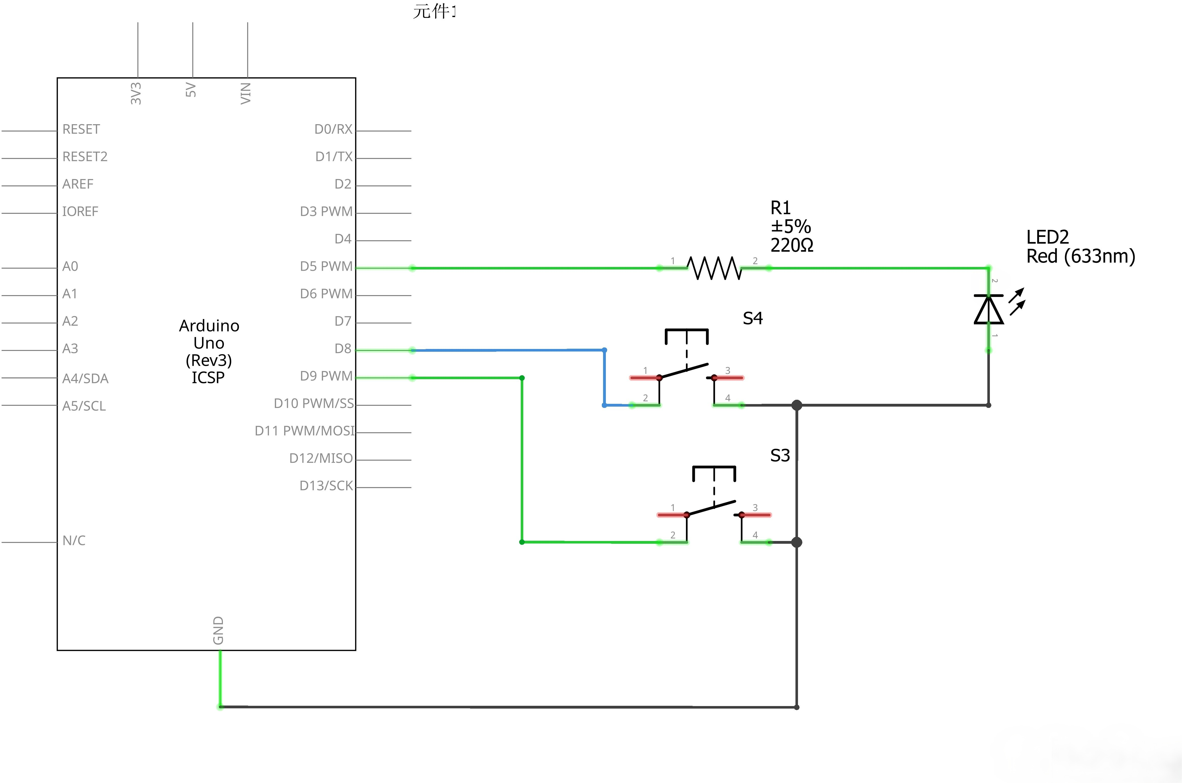
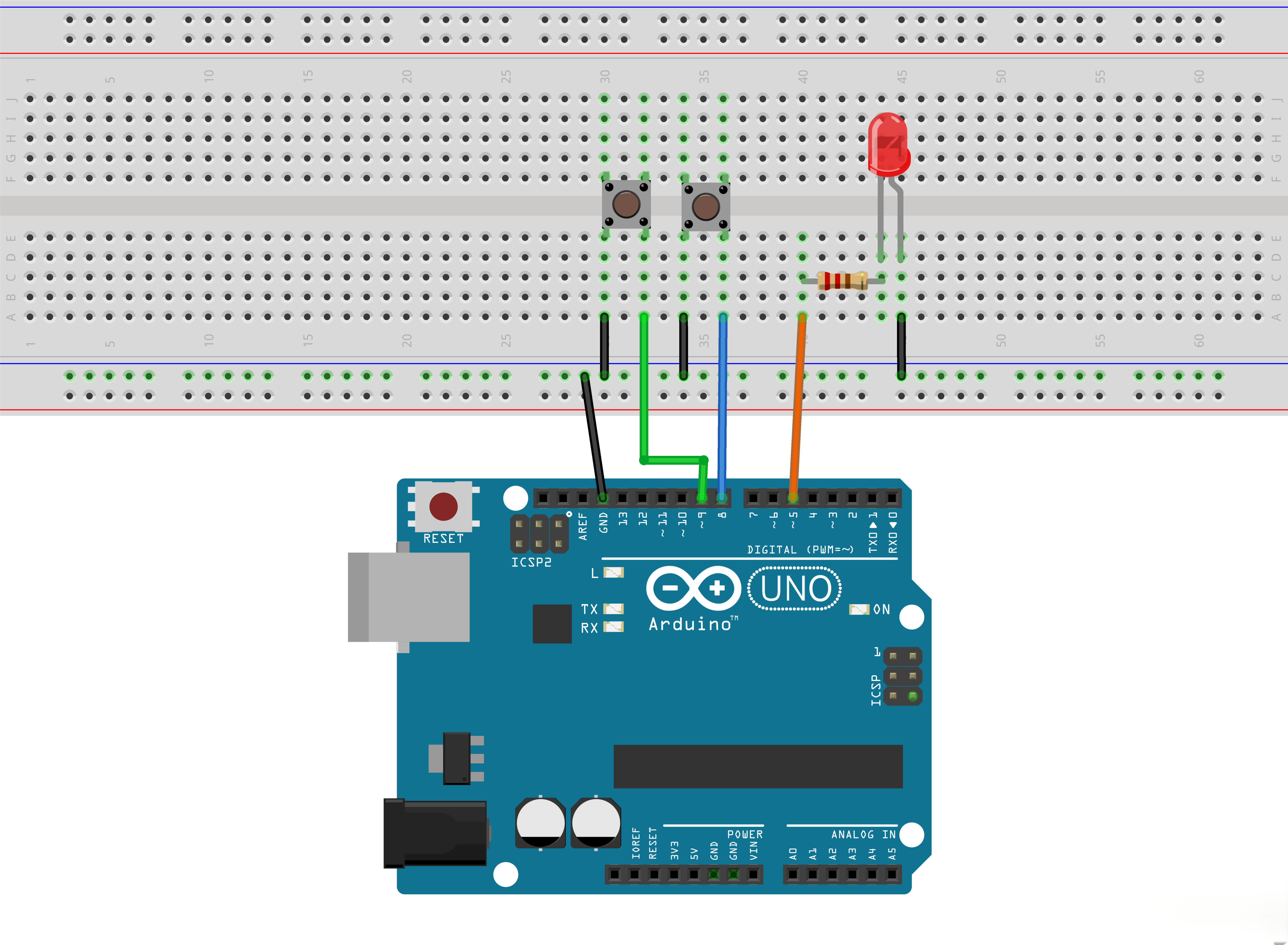
¶ Wiring diagram
¶ Code
You can click the blue text link to download the program file to your local device, and double-click the file to open it after the download is complete. Please note: Before opening the file, ensure that you have installed the Arduino IDE development environment and completed the installation of relevant components such as the board support package and driver corresponding to the UNO development board. If you have any questions about this operation process, you can refer to the "part 1" chapter of the document for detailed guidance.
The first part of the sketch defines three variables for the three pins that are to be used. The 'ledPin' is the output pin and 'buttonApin' will refer to the switch nearer the top of the breadboard and 'buttonBpin' to the other switch.
int ledPin = 5;
int buttonApin = 9;
int buttonBpin = 8;
The 'setup' function defines the ledPin as being an OUTPUT as normal, but now we have the two inputs to deal with. In this case, we use the set the pinMode to be INPUT_PULLUP like this:
void setup()
{
pinMode(ledPin, OUTPUT);
pinMode(buttonApin, INPUT_PULLUP);
pinMode(buttonBpin, INPUT_PULLUP);
}
The pin mode of INPUT_PULLUP means that the pin is to be used as an input, but that if nothing else is connected to the input, it should be 'pulled up' to HIGH. In other words, the default value for the input is HIGH, unless it is pulled LOW by the action of pressing the button.
This is why the switches are connected to GND. When a switch is pressed, it connects the input pin to GND, so that it is no longer HIGH.
Since the input is normally HIGH and only goes LOW when the button is pressed, the logic is a little upside down. We will handle this in the 'loop' function.
In the 'loop' function there are two 'if' statements. One for each button. Each does an 'digitalRead' on the appropriate input.
void loop()
{
if (digitalRead(buttonApin) == LOW)
{
digitalWrite(ledPin, HIGH);
}if (digitalRead(buttonBpin) == LOW)
{
digitalWrite(ledPin, LOW);
}
}
Remember that if the button is pressed, the corresponding input will be LOW, if button A is low, then a 'digitalWrite' on the ledPin turns it on.
Similarly, if button B is pressed, a LOW is written to the ledPin.
¶ If{}:
The if statement checks for a condition and executes the proceeding statement or set of statements if the condition is 'true'.
Parameters
- condition: a boolean expression (i.e., can be true or false).
¶ digitalRead():
Reads the value from a specified digital pin, either HIGH or LOW.
Syntax
digitalRead(pin)
Parameters
- pin: the Arduino pin number you want to read
Returns
- HIGH or LOW
¶ Comparison Operators
Description
Compares the variable on the left with the value or variable on the right of the operator. Returns true when the two operands are equal. Please note that you may compare variables of different data types, but that could generate unpredictable results, it is therefore recommended to compare variables of the same data type including the signed/unsigned type.
Syntax
x==y;//is true if x is equal to y and it is false if x is no equal to y
Parameters
- x: variable. Allowed data types: int, float, double, byte, short, long.
- y: variable or constant. Allowed data types: int, float, double, byte, short, long.