¶ RGB LED
¶ Overview
RGB LEDs are a fun and easy way to add some color to your projects. Since they are like 3 regular LEDs in one, using and connecting them is not much different.
They come mostly in 2 versions: Common Anode or Common Cathode.
Common Anode: uses 3.3-5V on the common pin.
Common Cathode: connects to ground.
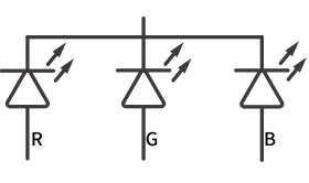
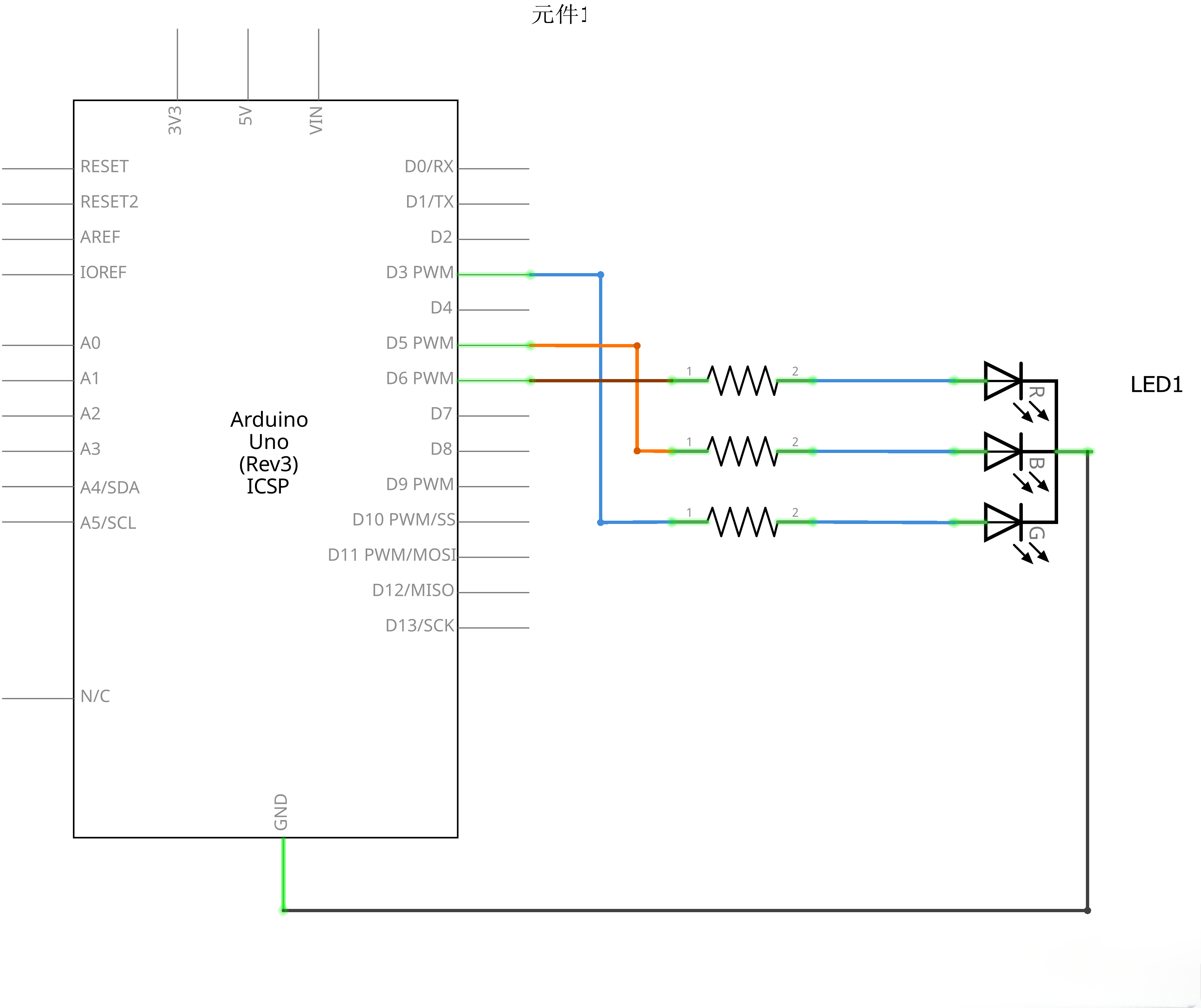
The RGB LED used in this tutorial is of the common cathode type. As illustrated in the following Connection Schematic, the common pin (cathode) of the RGB LED is uniformly connected to the GND (ground terminal) of the circuit, while the control pins corresponding to the red, green, and blue color channels need to be connected to the GPIO pins of the main control device respectively.
As with any LED, we need to connect some resistors inline (3 total) so we can limit the current being drawn.
In our sketch, we will start with the LED in the Red color state, then fade to Green, then fade to Blue and finally back to the Red color. By doing this we will cycle through most of the color that can be achieved.
¶ Component Required:
(1) x Elegoo Uno R3
(1) x 830 Tie Points Breadboard
(4) x M-M wires (Male to Male jumper wires)
(1) x RGB LED
(3) x 220 ohm resistors
¶ Component Introduction
¶ RGB:
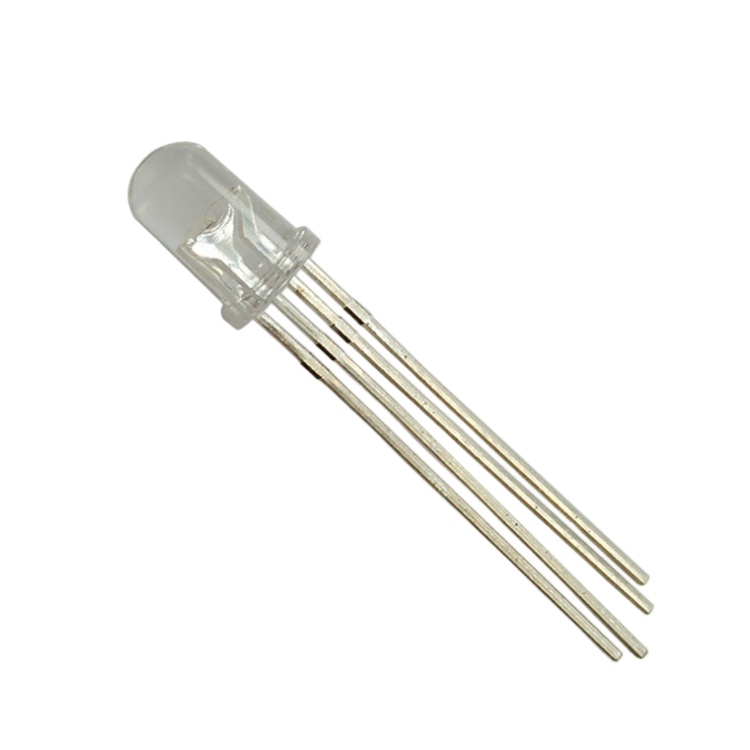
At first glance, RGB (Red, Green and Blue) LEDs look just like regular LEDs. However, inside the usual LED package, there are actually three LEDs, one red, one green and one blue. By controlling the brightness of each of the individual LEDs you can mix pretty much any color you want.
We mix colors the same way you would mix paint on a palette - by adjusting the brightness of each of the three
LEDs.The hard way to do this would be to use different value resistors( or variable resistors ) as we did with in Lesson 1, but that's a lot of work! Fortunately for us, The UNO R3 board has ananalogWrite function that you can use with pins marked with a to output a variable amount of power to the appropriate LEDs.
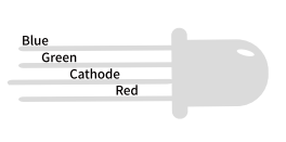
The RGB LED has four leads. There is one lead going to the positive connection of each of the single LEDs within the package and a single lead that is connected to all three negative sides of the LEDs.
The common negative connection of the LED package is the second pin from the flat side. It is also the longest of the four leads and will beconnected to the ground.
¶ COLOR:
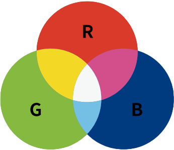
The reason that you can mix any color you like by varying the quantities of red, green and blue light is that your eye has three types of light receptor in it (red, green and blue). Your eye and brain process the amounts of red, green and blue and convert it into a color of the spectrum.
In a way, by using the three LEDs, we are playing a trick on the eye. This same idea is used in TVs, where the LCD has red, green and blue color dots next to each other making up each pixel.
If we set the brightness of all three LEDs to be the same, then the overall color of the light will be white. If we turn off the blue LED, so that just the red and green LEDs are the same brightness, then the light will appear yellow. We can control the brightness of each of the red, green and blue parts of the LED separately, making it possible to mix any color we like.
Black is not so much a color as an absence of light. Therefore, the closest we can come to black with our LED is to turn off all three colors.
¶ Theory (PWM)
Pulse Width Modulation (PWM) is a technique for controlling power. We also use it here to control the brightness of each of the LEDs.The diagram below shows the signal from one of the PWM pins on the UNO.
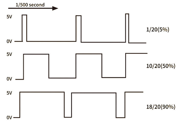
Roughly every 1/500 of a second, the PWM output will produce a pulse.The length of this pulse is controlled by the 'analogWrite' function. So 'analogWrite(0)' will not produce any pulse at all and 'analogWrite(255) ' will produce a pulse that lasts all the way until the next pulse is due, so that the output is actually on all the time.
If we specify a value in the analogWrite that is somewhere in between 0 and 255, then we will produce a pulse.
If the output pulse is only high for 5% of the time, then whatever we are driving will only receive 5% of full power.
If, however, the output is at 5V for 90% of the time, then the load will get 90% of the power delivered to it. We cannot see the LEDs turning on and off at that speed, so to us, it just looks like the brightness is changing.
¶ Connection Schematic
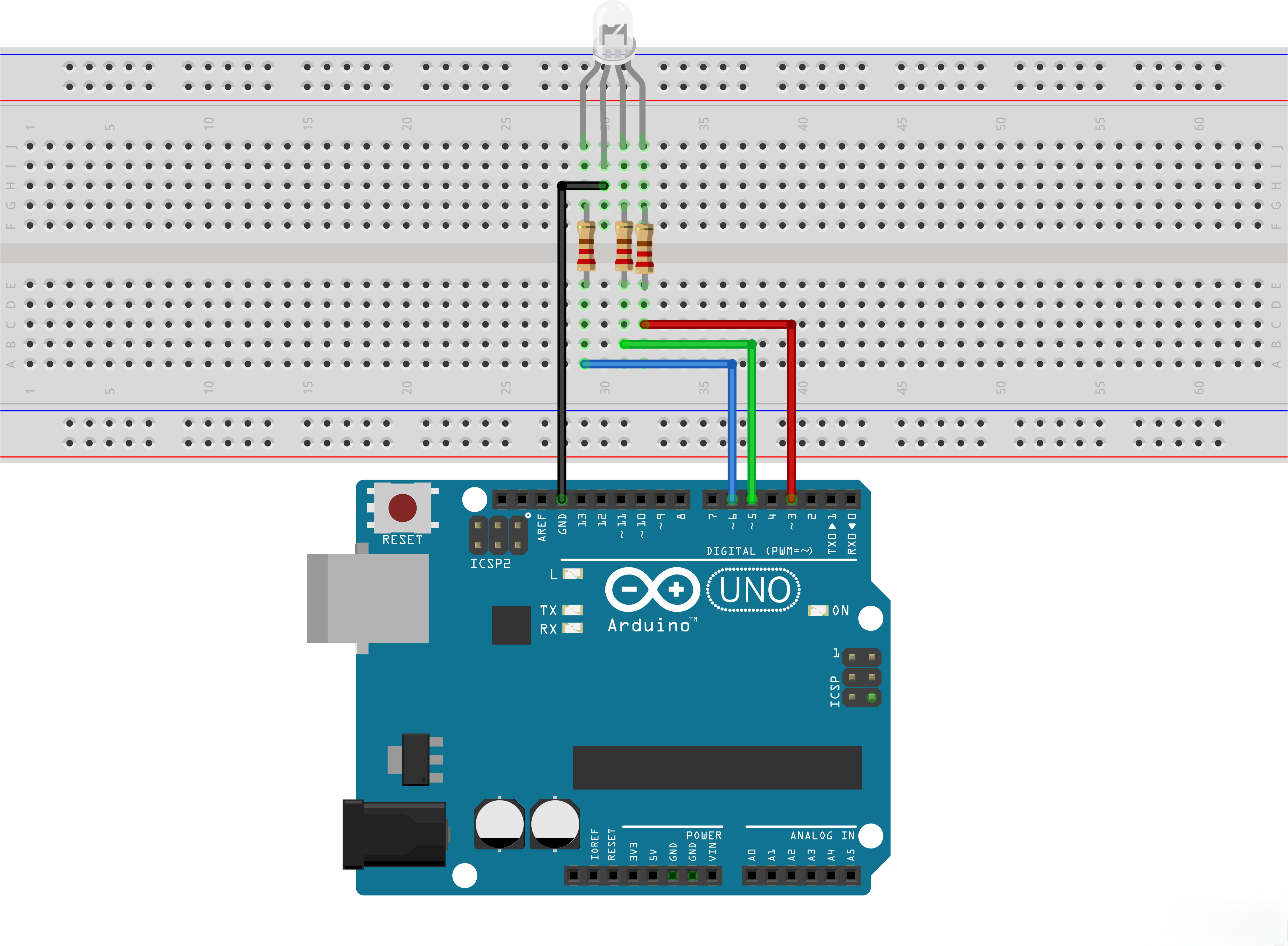
¶ Wiring diagram
¶ Code
You can click the blue text link to download the program file to your local device, and double-click the file to open it after the download is complete. Please note: Before opening the file, ensure that you have installed the Arduino IDE development environment and completed the installation of relevant components such as the board support package and driver corresponding to the UNO development board. If you have any questions about this operation process, you can refer to the "part 1" chapter of the document for detailed guidance.
#define BLUE 3
#define GREEN 5
#define RED 6
¶ #define constantName value:
is a useful C++ component that allows the programmer to give a name to a constant value before the program is compiled. Defined constants in arduino don’t take up any program memory space on the chip. The compiler will replace references to these constants with the defined value at compile time.
This can have some unwanted side effects though, if for example, a constant name that had been #defined is included in some other constant or variable name. In that case the text would be replaced by the #defined number (or text).
Parameters
constantName: the name of the macro to define. value: the value to assign to the macro.
Notes and Warnings
There is no semicolon after the #define statement. If you include one, the compiler will throw cryptic errors further down the page.
#define ledPin 3; // this is an error
Similarly, including an equal sign after the #define statement will also generate a cryptic compiler error further down the page.
#define ledPin = 3 // this is also an error
The next step is to write the 'setup' function. As we have learnt in earlier lessons, the setup function runs just once after the Arduino has reset. In this case, all it has to do is define the three pins we are using as being outputs.
void setup()
{
pinMode(RED, OUTPUT);
pinMode(GREEN, OUTPUT);
pinMode(BLUE, OUTPUT);
digitalWrite(RED, HIGH);
digitalWrite(GREEN, LOW);
digitalWrite(BLUE, LOW);
}
pinMode(pin, mode):Configures the specified pin to behave either as an input or an output.
As of Arduino 1.0.1, it is possible to enable the internal pullup resistors with the mode INPUT_PULLUP. Additionally, the INPUT mode explicitly disables the internal pullups.
Parameters
pin: the UNO pin number to set the mode of.
mode: INPUT, OUTPUT, or INPUT_PULLUP. See the Digital Pins page for a more complete description of the functionality.
// define variables
int redValue;
int greenValue;
int blueValue;
Int:is the Data Types. Integers are your primary data-type for number storage.
On the UNO(and other ATmega based boards) an int stores a 16-bit (2-byte) value. This yields a range of -32,768 to 32,767
(minimum value of -2^15 and a maximum value of (2^15) - 1). On the Arduino Due and SAMD based boards (like MKR1000 and Zero), an int stores a 32-bit (4-byte) value.
This yields a range of -2,147,483,648 to 2,147,483,647 (minimum value of -2^31 and a maximum value of (2^31) - 1).int’s store negative numbers with a technique called (2’s complement math). The highest bit, sometimes referred to as the "sign" bit, flags the number as a negative number. The rest of the bits are inverted and 1 is added.
Syntax
int var=val
Parameters
var: variable name.
val: the value you assign to that variable.
Before we take a look at the 'loop' function, let’s look at the last function in the sketch.
The define variables
redValue = 255; // choose a value between 1 and 255 to change the color.
greenValue = 0;
blueValue = 0;
This function takes three arguments, one for the brightness of the red, green and blue LEDs. In each case the number will be in the range 0 to 255, where 0 means off and 255 means maximum brightness. The function then calls 'analogWrite' to set the brightness of each LED.
Try adding a few colors of your own to the sketch and watch the effect on your LED.
for (int i = 0; i < 255; i += 1) // fades out red bring green full when i=255**
{
redValue -= 1;
greenValue += 1;
// The following was reversed, counting in the wrong directions
// analogWrite(RED, 255 - redValue);
// analogWrite(GREEN, 255 - greenValue);
analogWrite(RED, redValue);
analogWrite(GREEN, greenValue);
delay(delayTime);
}
¶ for
[Control Structure]
Description
The for statement is used to repeat a block of statements enclosed in curly braces. An increment counter is usually used to increment and terminate the loop.
The for statement is useful for any repetitive operation, and is often used in combination with arrays to operate on collections of data/pins.
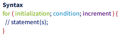
Parameters
initialization: happens first and exactly once.
condition:each time through the loop, condition is tested; if it’s true, the statement blocks, and the increment is executed, then the condition is tested again. When the condition becomes false, the loop ends.
increment: executed each time through the loop when condition is true.
¶ =
[Arithmetic Operators]
Description
The single equal sign = in the C++ programming language is called the assignment operator. It has a different meaning than in algebra class where it indicated an equation or equality. The assignment operator tells the microcontroller to evaluate whatever value or expression is on the right side of the equal sign, and store it in the variable to the left of the equal sign.
Notes and Warnings
The variable on the left side of the assignment operator ( = sign ) needs to be able to hold the value stored in it. If it is not large enough to hold a value, the value stored in the variable will be incorrect.
Don’t confuse the assignment operator [ = ] (single equal sign) with the comparison operator [ == ] (double equal signs), which evaluates whether two expressions are equal.
¶ += / -=
[Compound Operators]
Description
This is a convenient shorthand to perform addition/subtraction on a variable with another constant or variable.
Parameters
x: variable. Allowed data types: int, float, double, byte,short, long.
y: variable or constant. Allowed data types: int, float, double, byte, short, long.