¶ Tilt Switch
¶ Overview
In this tutorial , you will learn how to use a tilt ball switch in order to detect a small angle of inclination.
¶ Component Required:

(1) x Elegoo Uno R3
(1) x Servo (SG90)
(3) x M-M wires (Male to Male jumper wires)
¶ Component Introduction
¶ Tilt sensor:
Tilt sensors (tilt ball switch) allow you to detect orientation or inclination. They are small, inexpensive, low-power and easy-to-use. If used properly, they will not wear out. Their simplicity makes them popular for toys, gadgets and appliances.
Sometimes, they are referred to as "mercury switches", "tilt switches" or "rolling ball sensors" for obvious reasons.
They are usually made up of a cavity of some sort (cylindrical is popular, although not always) with a conductive free mass inside, such as a blob of mercury or rolling ball. One end of the cavity has two conductive elements (poles). When the sensor is oriented so that that end is downwards, the mass rolls onto the poles and shorts them, acting as a switch throw.
While not as precise or flexible as a full accelerometer, tilt switches can detect motion or orientation. Another benefit is that the big ones can switch power on their own.
Accelerometers, on the other hand, output digital or analog voltage that must then be analyzed using extra circuitry.
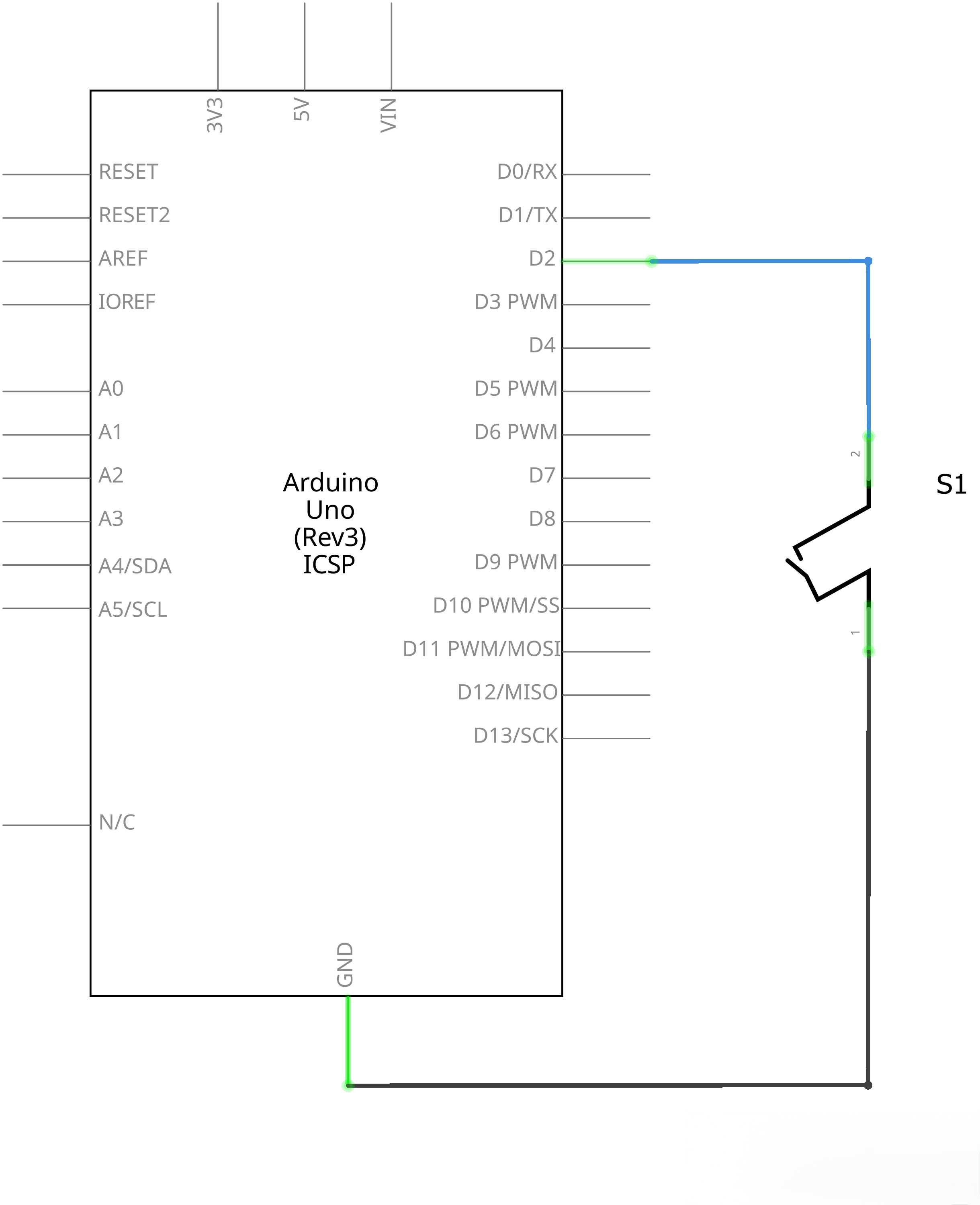
¶ Connection Schematic
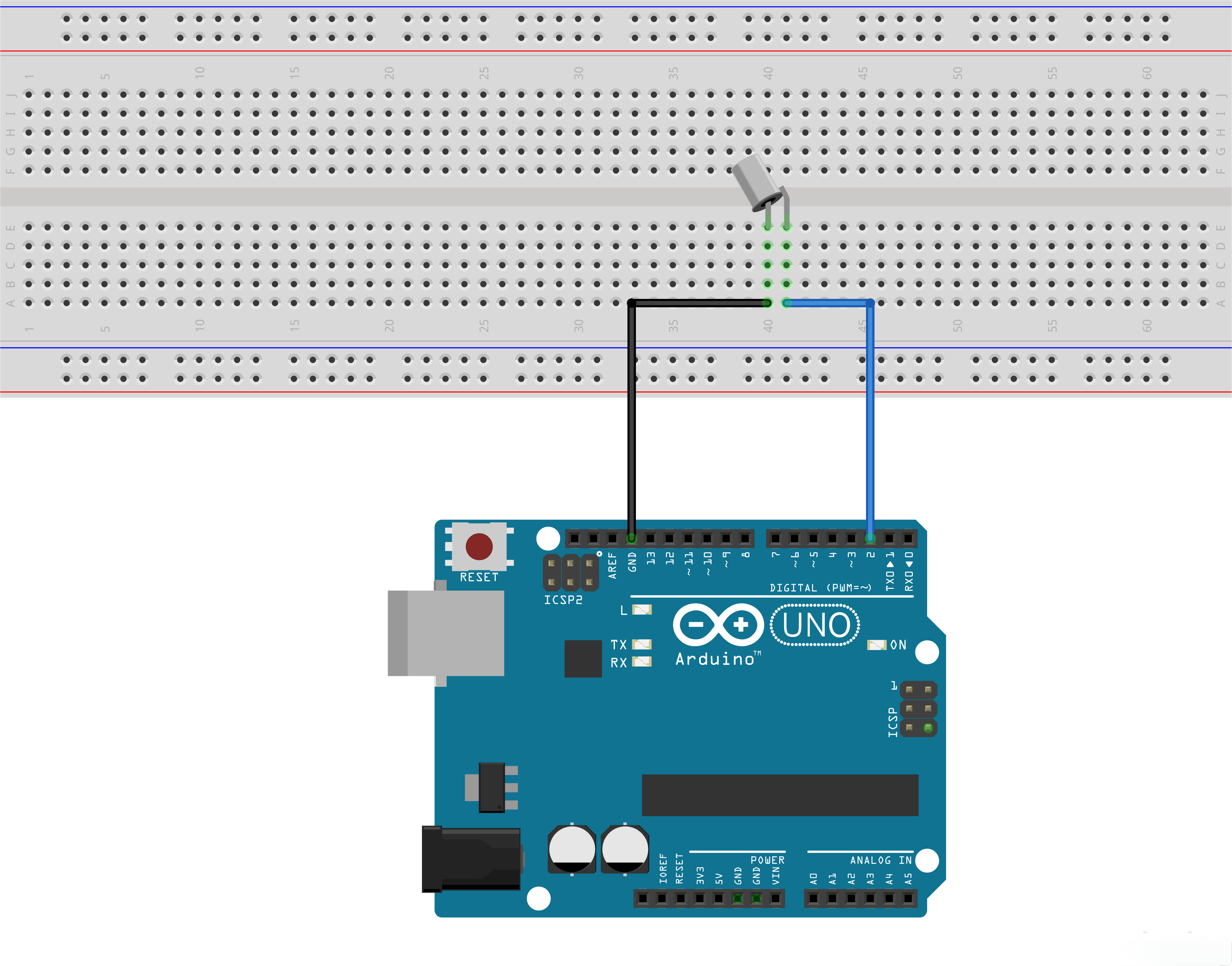
¶ Wiring diagram
¶ Code
You can click the blue text link to download the program file to your local device, and double-click the file to open it after the download is complete. Please note: Before opening the file, ensure that you have installed the Arduino IDE development environment and completed the installation of relevant components such as the board support package and driver corresponding to the UNO development board. If you have any questions about this operation process, you can refer to the "part 1" chapter of the document for detailed guidance.
const int ledPin = 13;//the led attach to
Hardware Configuration:
const int ledPin = 13: Defines the LED pin (GPIO 2) where the LED is connected
void setup()
{
pinMode(ledPin,OUTPUT);//initialize the ledPin as an output
pinMode(5,INPUT);
}
setup() Function:Initializes the system and configures the GPIO pins.
pinMode(ledPin, OUTPUT): Configures the LED pin as an outputpinMode(5, INPUT): Configures pin 5 as a digital input (tilt sensor)
void loop()
{
int digitalVal = digitalRead(5); //read pin 5
if(LOW == digitalVal)
{
digitalWrite(ledPin,HIGH);//turn the led on
}
else
{
digitalWrite(ledPin,LOW);//turn the led off
}
}
loop() Function Overview:The main loop that continuously checks the tilt sensor state and controls the LED.
1. Tilt Sensor State Reading Module:
int digitalVal = digitalRead(5); //read pin 5
digitalRead(5): Reads the digital value from pin 5 (tilt sensor)- Stores the result in the integer variable
digitalVal - The pin state changes when the sensor is tilted from its normal position
2. LED Control Module:
if(HIGH == digitalVal)
{
digitalWrite(ledPin,HIGH);//turn the led on
}
else
{
digitalWrite(ledPin,LOW);//turn the led off
}
- Conditional Logic: Checks the tilt sensor state and controls the LED accordingly
- Sensor Tilted:
digitalValis LOW, so LED is turned on - Sensor Normal:
digitalValis HIGH, so LED is turned off - digitalWrite(ledPin, HIGH): Turns the LED on
- digitalWrite(ledPin, LOW): Turns the LED off
Digital Input States:
| Sensor State | Pin 5 Value | LED State |
|---|---|---|
| Normal | LOW (0) | Off |
| Tilted | HIGH(1) | On |
Digital Input Fundamentals:
- Digital inputs can only read two states: HIGH (1) or LOW (0)
- Input voltage levels:
- HIGH: Approximately 2.5V to 3.3V ( logic high)
- LOW: Approximately 0V to 0.8V (logic low)
- Input impedance is high, so minimal current flows into the pin
Troubleshooting:
- LED always on: Confirm whether one section of tilt sensor is connected to VCC pin, if yes, please replace it with GND pin.
- LED always off: Check that the pins are correctly connected to the corresponding ports
- Intermittent operation: Check for loose connections or sensor stability
Applications:
- Simple tilt detection systems
- Alarm triggering for inclination changes
- Motion-sensitive projects
- Basic level sensing
- Interactive toys and games
- Home security systems