¶ MAX7219 LED Dot Matrix
¶ Overview
In this tutorial,we will connect a MAX7219 and scroll the text across.
Since these modules use the MAX7219 LED driver chip, we will be able to turn on and off the 64 LEDs of each module, using only 3 pins on our UNO.
¶ Component Required:
(1) x Elegoo Uno R3
(1) x Max7219 module
(5) x M-M wires (Male to Male jumper wires)
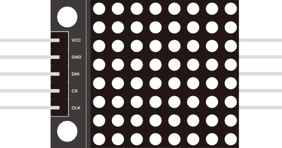
¶ Component Introduction
Our project is in fact an Arduino Serially Interfaced to MAX7219 that Operates an 8X8 LED Matrix .
The MAT7219 IC is a serial input/output common-cathode display driver that interfaces microprocessors to a 7-segment numeric LED displays of up to 8 digits, bar-graph displays, or 64 individual LEDs.
For convenience, here an 8×8 LED matrix, integrated with a MAX7219 IC setup, available as a pre-wired module is used. Typical specification of this LED Matrix Module is shown below:
- Operating Voltage: DC 4.7V ‒ 5.3V
- Typical Voltage: 5V
- Operating Current: 320mA
- Max Operating Current: 2A
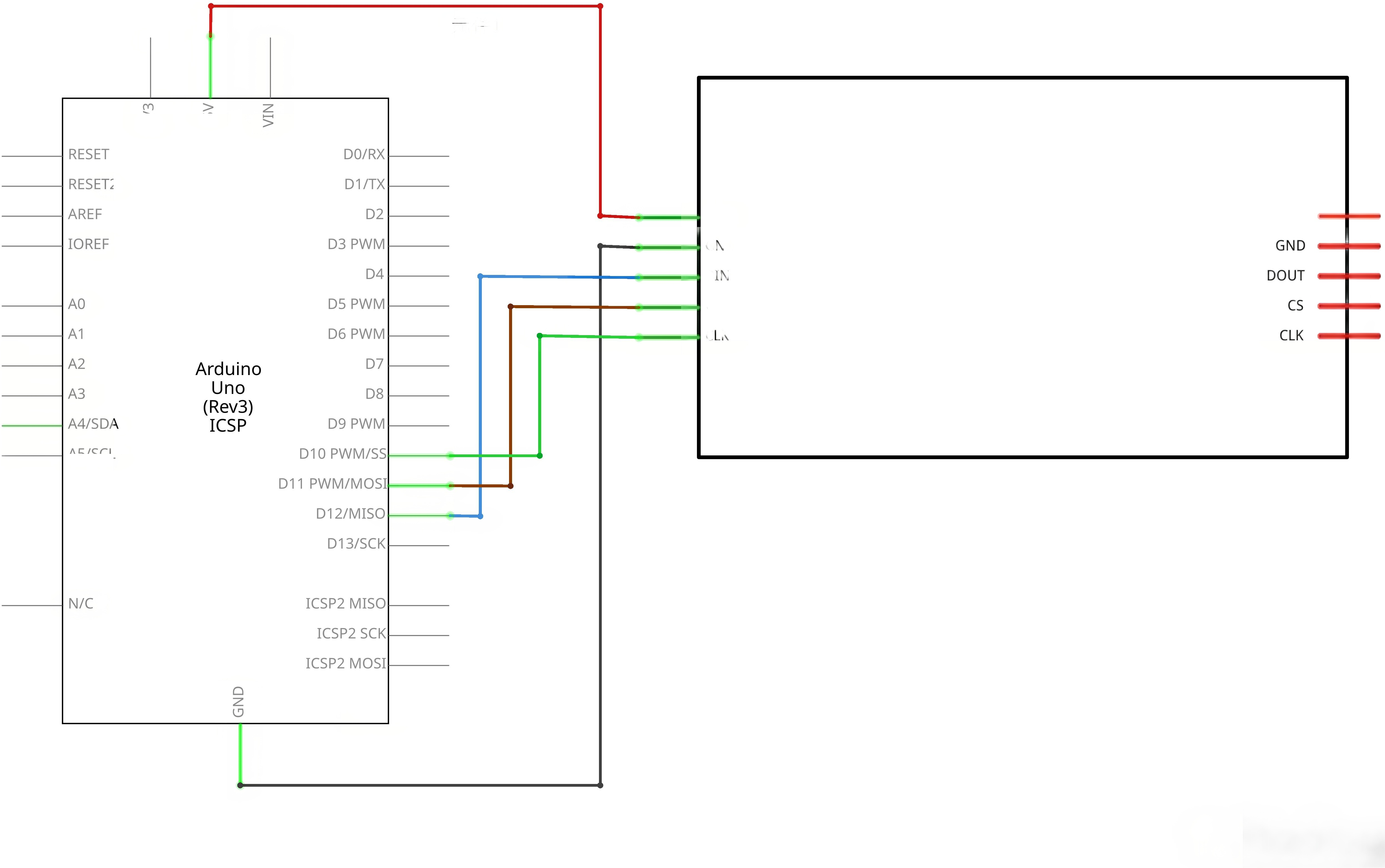
¶ Connection Schematic
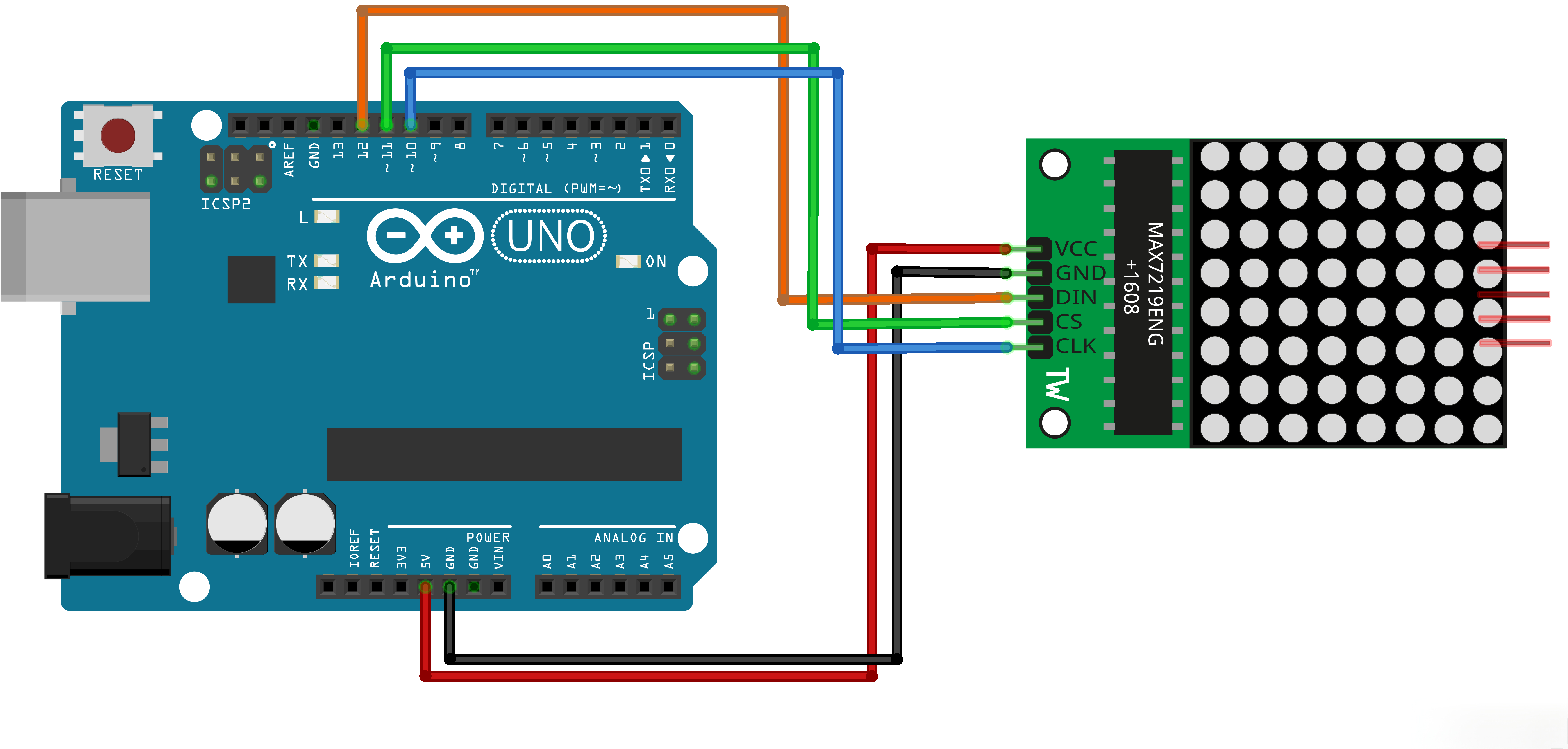
¶ Wiring diagram
¶ Code
You can click the blue text link to download the program file to your local device, and double-click the file to open it after the download is complete. Please note: Before opening the file, ensure that you have installed the Arduino IDE development environment and completed the installation of relevant components such as the board support package and driver corresponding to the UNO R3. If you have any questions about this operation process, you can refer to the "part 1" chapter of the document for detailed guidance.
This code demonstrates how to use a LedControl library to control a MAX72XX LED matrix. It displays the word "Arduino" and various animation effects on the matrix.
Click the Serial Monitor button to turn on the serial monitor. The basics about the serial monitor are introduced in details in tutorial 4 in part 2.
//We always have to include the library
#include "LedControl.h"/*
Now we need a LedControl to work with.
***** These pin numbers will probably not work with your hardware *****
pin 12 is connected to the DataIn
pin 11 is connected to LOAD(CS)
pin 10 is connected to the CLK
We have only a single MAX72XX.
*/
LedControl lc=LedControl(12,10,11,1);/* image switching time */
unsigned long delaytime1=500;
unsigned long delaytime2=50;
Includes and Definitions:
#include "LedControl.h":Includes the LedControl library for MAX72XX LED matrix controlLedControl lc=LedControl(12,10,11,1);:Creates LedControl object with specified pins (DataIn, CLK, LOAD, number of devices)unsigned long delaytime1=500;:Delay time for image switching (500ms)unsigned long delaytime2=50;:Delay time for animation effects (50ms)
void setup() {
/*
The MAX72XX is in power-saving mode on startup,
we have to do a wakeup call
/
lc.shutdown(0,false);
/ Set the brightness to a medium values /
lc.setIntensity(0,8);
/ and clear the display */
lc.clearDisplay(0);
}
Setup Function:
lc.shutdown(0,false);:Wakes up the MAX72XX from power-saving modelc.setIntensity(0,8);:Sets the brightness to medium value (0-15)lc.clearDisplay(0);:Clears the display
/*
This method will display the characters for the
word "Arduino" one after the other on the matrix.
(you need at least 5x7 leds to see the whole chars)
/
void writeArduinoOnMatrix() {
/ here is the data for the characters */
byte a[5]={B01111110,B10001000,B10001000,B10001000,B01111110};
byte r[5]={B00010000,B00100000,B00100000,B00010000,B00111110};
byte d[5]={B11111110,B00010010,B00100010,B00100010,B00011100};
byte u[5]={B00111110,B00000100,B00000010,B00000010,B00111100};
byte i[5]={B00000000,B00000010,B10111110,B00100010,B00000000};
byte n[5]={B00011110,B00100000,B00100000,B00010000,B00111110};
byte o[5]={B00011100,B00100010,B00100010,B00100010,B00011100};/* now display them one by one with a small delay */
lc.setRow(0,0,a[0]);
lc.setRow(0,1,a[1]);
lc.setRow(0,2,a[2]);
lc.setRow(0,3,a[3]);
lc.setRow(0,4,a[4]);
delay(delaytime1);
lc.setRow(0,0,r[0]);
lc.setRow(0,1,r[1]);
lc.setRow(0,2,r[2]);
lc.setRow(0,3,r[3]);
lc.setRow(0,4,r[4]);
delay(delaytime1);
lc.setRow(0,0,d[0]);
..........
}
writeArduinoOnMatrix() Function:
- Defines byte arrays for each character in "Arduino"
- Displays each character on the matrix one by one with a delay
- Clears the display after showing all characters
/*
This function lights up some Leds in a row.
The pattern will be repeated on every row.
The pattern will blink along with the row-number.
row number 4 (index==3) will blink 4 times etc.
*/
void rows() {
for(int row=0;row<8;row++) {
delay(delaytime2);
lc.setRow(0,row,B10100000);
delay(delaytime2);
lc.setRow(0,row,(byte)0);
for(int i=0;i<row;i++) {
delay(delaytime2);
lc.setRow(0,row,B10100000);
delay(delaytime2);
lc.setRow(0,row,(byte)0);
}
}
}
rows() Function:
- Lights up LEDs in a row pattern
- Each row blinks a number of times equal to its row index
- Uses a pattern of B10100000 for each row
/*
This function lights up some Leds in a column.
The pattern will be repeated on every column.
The pattern will blink along with the column-number.
column number 4 (index==3) will blink 4 times etc.
*/
void columns() {
for(int col=0;col<8;col++) {
delay(delaytime2);
lc.setColumn(0,col,B10100000);
delay(delaytime2);
lc.setColumn(0,col,(byte)0);
for(int i=0;i<col;i++) {
delay(delaytime2);
lc.setColumn(0,col,B10100000);
delay(delaytime2);
lc.setColumn(0,col,(byte)0);
}
}
}
columns() Function:
- Lights up LEDs in a column pattern
- Each column blinks a number of times equal to its column index
- Uses a pattern of B10100000 for each column
/*
This function will light up every Led on the matrix.
The led will blink along with the row-number.
row number 4 (index==3) will blink 4 times etc.
*/
void single() {
for(int row=0;row<8;row++) {
for(int col=0;col<8;col++) {
delay(delaytime2);
lc.setLed(0,row,col,true);
delay(delaytime2);
for(int i=0;i<col;i++) {
lc.setLed(0,row,col,false);
delay(delaytime2);
lc.setLed(0,row,col,true);
delay(delaytime2);
}
}
}
}
single() Function:
- Lights up each LED on the matrix individually
- Each LED blinks a number of times equal to its column index
- Iterates through all rows and columns
void loop() {
writeArduinoOnMatrix();
rows();
columns();
single();
}
Loop Function:
- Calls the functions in sequence to display different effects
writeArduinoOnMatrix();:Displays the word "Arduino"rows();:Shows row animationcolumns();:Shows column animationsingle();:Shows single LED animation
¶ Troubleshooting
- LED Matrix Not Responding:Check connections between Arduino and MAX72XX
- Incorrect Display:Verify pin connections match the LedControl initialization
- Dim Display:Adjust the brightness using
lc.setIntensity() - No Animation:Check that the LedControl library is properly installed
- Wiring Issues:Ensure all connections are secure and correct
¶ Pin Connections
| Arduino Pin | MAX72XX Pin | Function |
|---|---|---|
| Digital 12 | DataIn | Data input |
| Digital 10 | CLK | Clock input |
| Digital 11 | LOAD(CS) | Load input |
| 5V | VCC | Power |
| GND | GND | Ground |