¶ Water Level Detection Sensor
¶ Overview
In this lesson, you will learn how to use a water level detection sensor module.
This module can perceive the depth of water and the core component is an amplifying circuit which is made up of a transistor and several pectinate PCB routings. When put into the water, these routings will present a resistor that can change along with the change of the water’s depth. Then, the signal of water’s depth is converted into the electrical signal, and we can know the change of water’s depth through the ADC function of UNO R3.
¶ Component Required:
(1) x Elegoo Uno R3
(3) x F-M wires (Female to Male DuPont wires)
(1) x Water lever detection sensor module
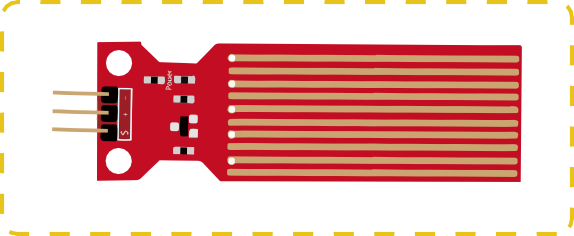
¶ Component Introduction
A water sensor brick is designed for water detection, which can be widely used in sensing the rainfall, water level, even the liquate leakage. The brick is mainly composed of three parts: an electronic brick connector, a 1 MΩ resistor, and several lines of bare conducting wires.
This sensor works by having a series of exposed traces connected to ground.
Interlaced between the grounded traces are the sense traces.
The sensor traces have a weak pull-up resistor of 1 MΩ. The resistor will pull the sensor trace value
high until a drop of water shorts the sensor trace to the grounded trace. Believe it or not this circuit will work with the digital I/O pins of your UNO R3 board or you can use it with the analog pins to detect the amount of water induced contact between the grounded and sensor traces.
This item can judge the water level through with a series of exposed parallel wires stitch to measure the water droplet/water size. It can easily change the water size to analog signal, and output analog value can directly be used in the program function, then to achieve the function of water level alarm.
It has low power consumption, and high sensitivity.
¶ Features:
- Working voltage: 5V
- Working Current: <20ma
- Interface: Analog
- Width of detection: 40mm×16mm
- Working Temperature: 10℃~30℃
- Output voltage signal: 0~2.4V
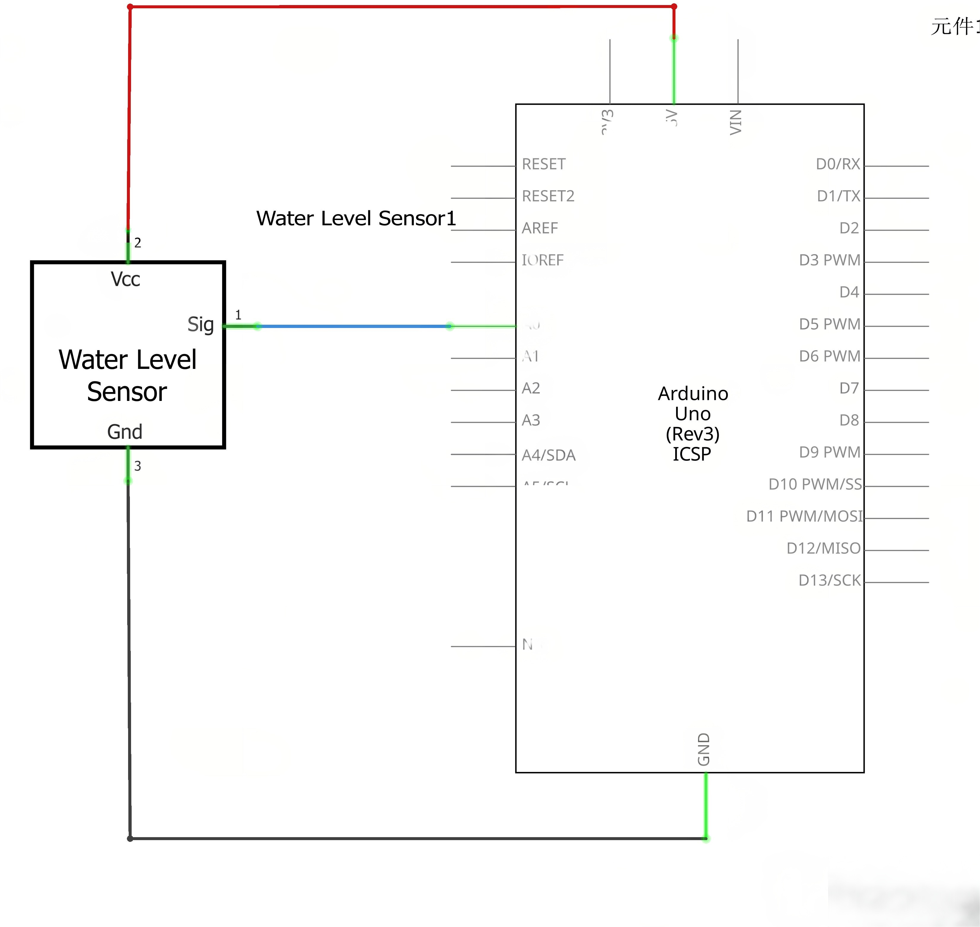
¶ Connection Schematic
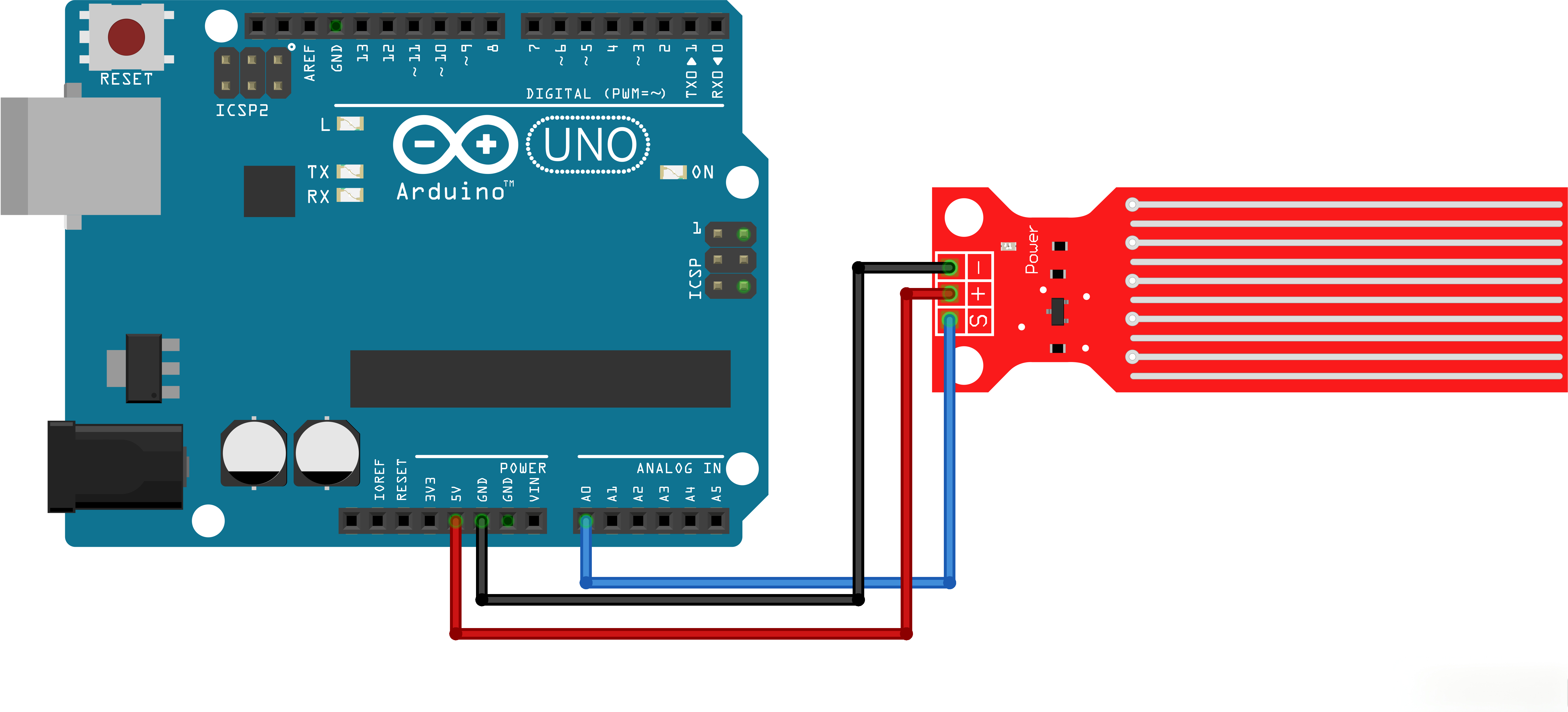
¶ Wiring diagram
¶ Code
You can click the blue text link to download the program file to your local device, and double-click the file to open it after the download is complete. Please note: Before opening the file, ensure that you have installed the Arduino IDE development environment and completed the installation of relevant components such as the board support package and driver corresponding to the UNO R3. If you have any questions about this operation process, you can refer to the "part 1" chapter of the document for detailed guidance.
Click the Serial Monitor button to turn on the serial monitor. The basics about the serial monitor are introduced in details in tutorial 4 in part 2.
int adc_id = 0;
int HistoryValue = 0;
char printBuffer[128];void setup()
{
Serial.begin(9600);
}
Variables and Setup:
int adc_id = 0;:Sets the ADC channel to 0 (Arduino pin A0)int HistoryValue = 0;:Stores the previous ADC value for comparisonchar printBuffer[128];:Buffer for storing the string to be printedvoid setup():Initializes serial communication at 9600 baud rate
void loop()
{
int value = analogRead(adc_id); // get adc value/*&& (logical AND) operator truth table
false&&false=false
false&&true=false
true&&false=false
true&&true=true|| (logical OR) operator truth table
false||false=false
false||true=true
true||false=true
true||true=true
print level when the change is greater than or less than 10。
*/if(((HistoryValue>=value) && ((HistoryValue - value) > 10)) || ((HistoryValue<value) && ((value - HistoryValue) > 10))) { sprintf(printBuffer,"ADC %d level is %d\n",adc_id, value); //Convert binary numbers "adc_id" and "value" into strings, and store the whole string "ADC "adc_id" level is "value"\n"in C.Serial.print(printBuffer);
HistoryValue = value;
}
}
Loop Function:
int value = analogRead(adc_id);:Reads the analog value from the specified ADC channelif(((HistoryValue>=value) && ((HistoryValue - value) > 10)) || ((HistoryValue<value) && ((value - HistoryValue) > 10))):Checks if the current value has changed by more than 10 compared to the previous valuesprintf(printBuffer,"ADC %d level is %d\n",adc_id, value);:Formats the string with ADC channel and valueSerial.print(printBuffer);:Prints the formatted string to the serial monitorHistoryValue = value;:Updates the history value with the current value
¶ Troubleshooting
- No Data on Serial Monitor:Check serial monitor baud rate is set to 9600
- Sensor Not Responding:Verify sensor connection to analog pin A0
- Inconsistent Readings:Ensure sensor is properly calibrated and positioned
- No Change Detection:Adjust the threshold value (currently 10) based on sensor sensitivity
- Wiring Issues:Check all connections between sensor and Arduino
¶ Pin Connections
| Arduino Pin | Component | Function |
|---|---|---|
| A0 | Water Level Sensor | Analog input for sensor data |
| 5V | Water Level Sensor | Power |
| GND | Water Level Sensor | Ground |