¶ 74HC595 And Segment Display
¶ Overview
In this tutorial ,we will use the 74HC595 shift register to control the segment display. The segment display will show number from 0-9.
¶ Component Required:

(1) x Elegoo Uno R3
(1) x 830 tie-points breadboard
(1) x 74HC595 IC
(1) x 1 Digit 7-Segment Display
(8) x 220 Ωresistors
(26) x M-M wires (Male to Male jumper wires)
¶ Component Introduction
Seven segment display
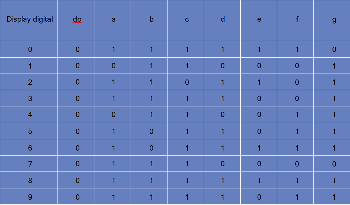
Below is the segment pin diagram.0-9 ten digits correspond with each segment are as follows (the following table applies common cathode seven segment
display device, if you are using a common anode, the table should be replaced every 1 0 (1->0,0->1).
0 should all replaced by 1
1 should all replaced by 0:
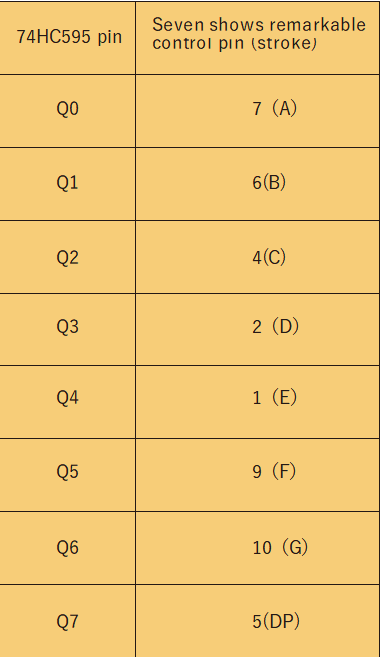
The following table shows the seven-segment display 74HC595 pin correspondence table:
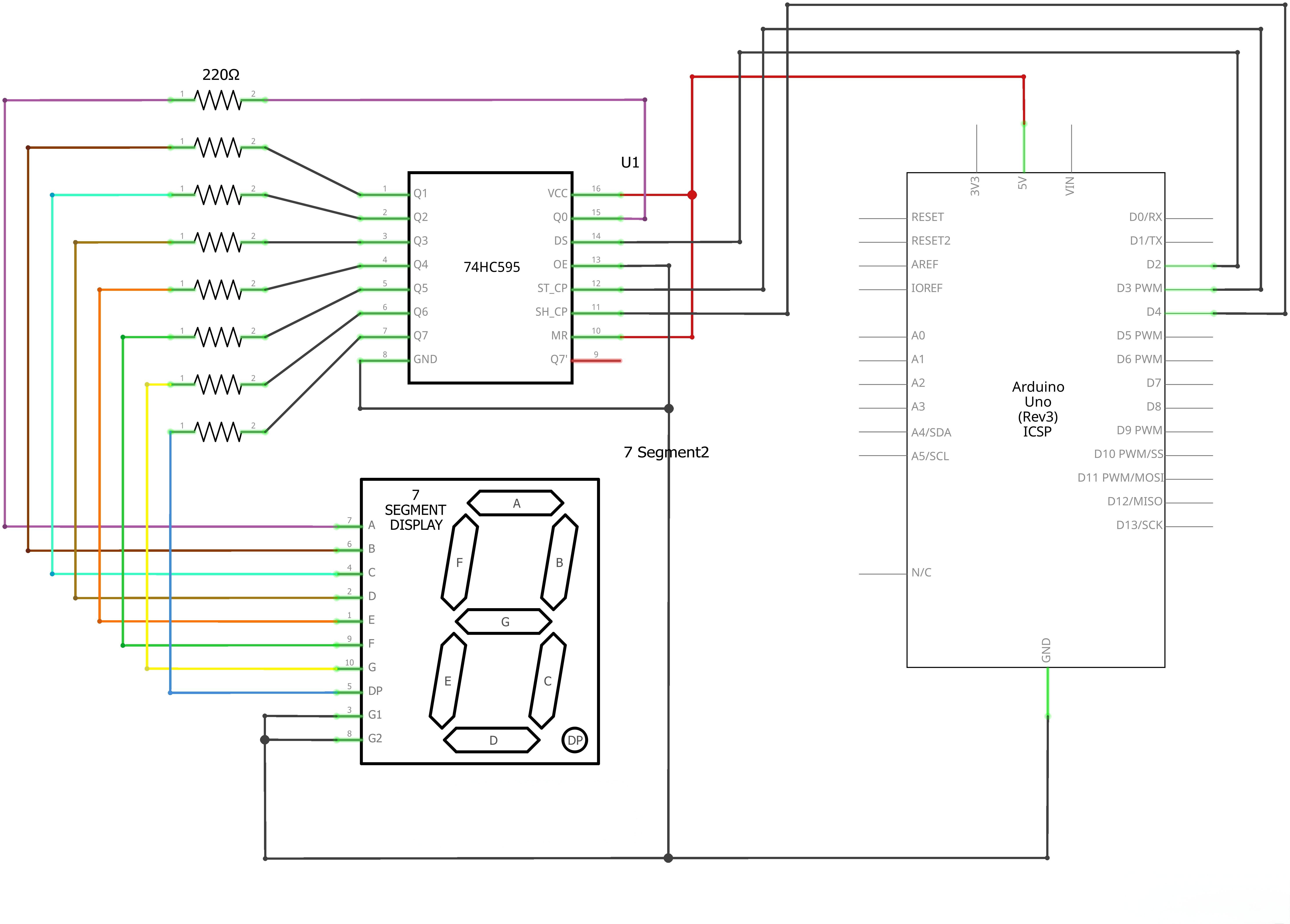
Step one: Connect 74HC595
.png)
First, the wiring is connected to power and ground:
VCC (pin 16) and MR (pin 10) connected to 3.3V
GND (pin 8) and OE (pin 13) to ground
Connection DS, ST_CP and SH_CP pin:
DS (pin 14) connected to UNO R3 D2
ST_CP (pin 12, latch pin) connected to UNO R3 D3
ST_CP (pin 11, clock pin) connected to UNO R3 D4
Step two: Connect the segment display
The seven-segment display 3 and 8 pins to the GND. (This example uses the common cathode, if you use the common anode, please connect 3 and 8 pins pin to + 3.3/5V)
According to the table above, connect the 74HC595 Q0 ~ Q7 to seven-segment display corresponding pin (A ~ G and DP), and then each lead in a 220Ω resistor in series..
¶ Connection Schematic
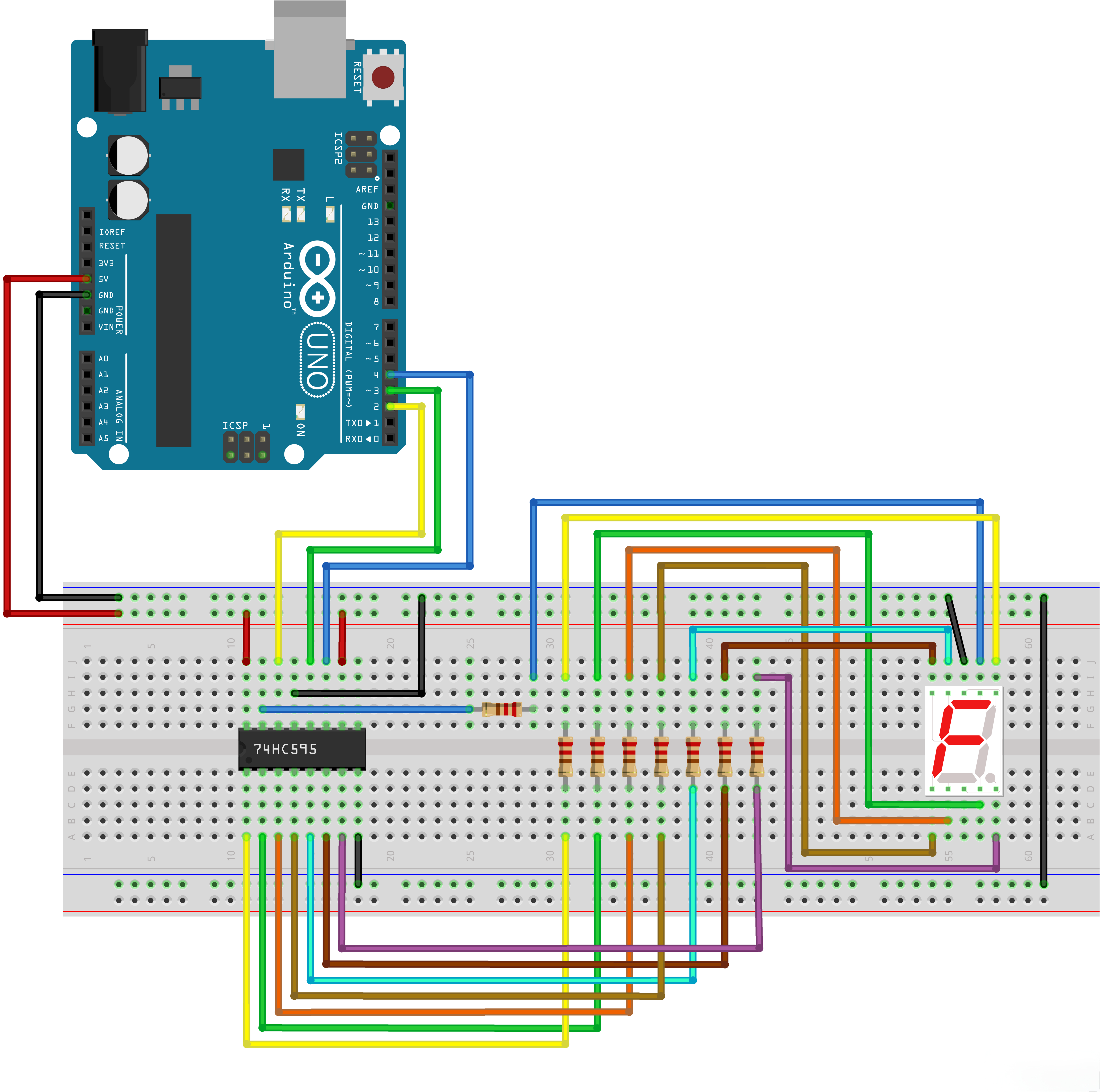
¶ Wiring diagram
¶ Code
You can click the blue text link to download the program file to your local device, and double-click the file to open it after the download is complete. Please note: Before opening the file, ensure that you have installed the Arduino IDE development environment and completed the installation of relevant components such as the board support package and driver corresponding to the UNO R3. If you have any questions about this operation process, you can refer to the "part 1" chapter of the document for detailed guidance.
This code demonstrates how to control a 7-segment LED display using a 74HC595 shift register. The display will count down from 9 to 0, then pause for 3 seconds before repeating the cycle.
Click the Serial Monitor button to turn on the serial monitor. The basics about the serial monitor are introduced in details in tutorial 4 in part 2.
// define the LED digit patterns, from 0 - 9
// 1 = LED on, 0 = LED off, in this order:
// 74HC595 pin Q0,Q1,Q2,Q3,Q4,Q5,Q6,Q7
// Mapping to a,b,c,d,e,f,g of Seven-Segment LED
byte seven_seg_digits[10] = { B11111100, // = 0
B01100000, // = 1
B11011010, // = 2
B11110010, // = 3
B01100110, // = 4
B10110110, // = 5
B10111110, // = 6
B11100000, // = 7
B11111110, // = 8
B11100110 // = 9
};
7-Segment Display Patterns:
byte seven_seg_digits[10]:Array of byte values representing the LED patterns for digits 0-9- Each byte corresponds to the 8 output pins of the 74HC595 shift register
- Pin mapping: Q0=a, Q1=b, Q2=c, Q3=d, Q4=e, Q5=f, Q6=g, Q7=unused/.
- The patterns use binary notation where 1 = LED on, 0 = LED off
// connect to the ST_CP of 74HC595 (pin 3,latch pin)
int latchPin = 3;
// connect to the SH_CP of 74HC595 (pin 4, clock pin)
int clockPin = 4;
// connect to the DS of 74HC595 (pin 2)
int dataPin = 2;
Pin Definitions:
int latchPin = 3;:Arduino digital pin 3 connected to ST_CP (pin 3) of 74HC595 (latch pin)int clockPin = 4;:Arduino digital pin 4 connected to SH_CP (pin 4) of 74HC595 (clock pin)int dataPin = 2;:Arduino digital pin 2 connected to DS (pin 2) of 74HC595 (data pin)
void setup() {
// Set latchPin, clockPin, dataPin as output
pinMode(latchPin, OUTPUT);
pinMode(clockPin, OUTPUT);
pinMode(dataPin, OUTPUT);
}
Setup Function:
pinMode(latchPin, OUTPUT);:Sets the latch pin as outputpinMode(clockPin, OUTPUT);:Sets the clock pin as outputpinMode(dataPin, OUTPUT);:Sets the data pin as output
// display a number on the digital segment display
void sevenSegWrite(byte digit) {
// set the latchPin to low potential, before sending data
digitalWrite(latchPin, LOW);// the original data (bit pattern)
shiftOut(dataPin, clockPin, LSBFIRST, seven_seg_digits[digit]);// set the latchPin to high potential, after sending data
digitalWrite(latchPin, HIGH);
}
sevenSegWrite() Function:
void sevenSegWrite(byte digit):Function to display a digit on the 7-segment displaydigitalWrite(latchPin, LOW);:Sets latch pin low to prepare for data transfershiftOut(dataPin, clockPin, LSBFIRST, seven_seg_digits[digit]);:Shifts out the bit pattern for the specified digitdataPin:Pin to send data throughclockPin:Pin to clock the dataLSBFIRST:Send least significant bit firstseven_seg_digits[digit]:Bit pattern for the digit
digitalWrite(latchPin, HIGH);:Sets latch pin high to update the display with new data
void loop() {
// count from 9 to 0
for (byte digit = 10; digit > 0; --digit) {
delay(1000);
sevenSegWrite(digit - 1);
}// suspend 4 seconds
delay(3000);
}
Loop Function:
for (byte digit = 10; digit > 0; --digit) { ... }:Counts down from 9 to 0delay(1000);:Delays 1 second between digitssevenSegWrite(digit - 1);:Displays the current digit (subtract 1 to convert from 10-1 to 9-0)delay(3000);:Pauses for 3 seconds after completing the countdown
¶ Troubleshooting
- Display Not Working:Check connections between Arduino, 74HC595, and 7-segment display
- Incorrect Digits:Verify the 7-segment pin mapping and bit patterns
- Flickering Display:Ensure proper power supply for the display and 74HC595
- Shift Register Issues:Check that the 74HC595 is receiving proper clock and data signals
- Wiring:Double-check the connections according to the pin definitions