¶ Digital Temperature Module
¶ Overview
In this experiment, we will learn how to use digital temperature module and analog temp module.
¶ Digital Temperature Module
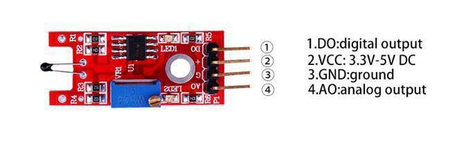
Temperature sensing module using an NTC thermistor. The output signal at ‘DO’ switches high when the preset (adjustable) temperature is reached. An analog output signal from the sensor is available at pin ‘AO’.
¶ Component Introduction
Thermistor:

What Is An NTC Thermistor
Thermistors are temperature-sensing elements made of semiconductor material that has been sintered in order to display large changes in resistance in proportion to small changes in temperature.
This resistance can be measured by using a small and measured direct current, or dc, passed through the thermistor in order to measure the voltage drop produced.
NTC Thermistors are non-linear resistors, which alter their resistance characteristics with temperature.
The resistance of NTC will decrease as the temperature increases. The manner in which the resistance decreases is related to a constant known in the electronics industry as beta, or ß. Beta is measured in °K.
The Arduino has several ADC ports that we can use to read a voltage, or rather an ‘ADC value’. If the Analog port is connected to Vcc, the max value one reads is 1023 and of course when connected to ground it is 0.
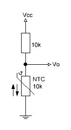
Now if we make a voltage divider which is typically two resistors in series between Vcc and Ground and the analogport in the middle, the reading will depend on the ratio of the two resistors: If they are equal, the reading will be 512, halfway to 1023. If one of the resistors, say the bottom one is an NTC, then the readings on the analogport will vary with the temperature:
If the temperature goes down, the value of the resistor increases and so will the reading on the analog port.
Suppose we have a 10k Series resistor and an NTC that for now we call ‘R’.
Then the voltage that can be measured in the middle is Vo=R/(R+10K) * Vcc
The analogPort readings however don’t give a voltage but an ADC value that can easily be calculated
ADC value= Vo*1023/Vcc // if for instance the Vo=4Volt the ADC = 818
or ADC value= 1023*Vo/Vcc
If we now combining the two formulas or as it is called ‘substitute’ Vo in the formula for ADC we get the
following:
ADC value= (R/(R+10K))Vcc1023/Vcc
As we multiply by Vcc but also divide by Vcc we can take that out of the equation and end up with
ADC value= (R/(R+10k))*1023
ADC value= 1023*R/(10+R)
if we want to get the value of R out of that equation, that becomes R=10k/(1023/ADC-1)
If that goes a bit too fast, here is the equation worked out. I prefer pictures over the ‘in line’ formulas as some people have problems understanding the PEMDAS / BODMAS order of operation.
So, as long as we know the value of the series resistor, we can calculate the value of the NTC from the measured ADC value. Now remember, this is valid voor a pull-up configuration. If it is a pull down configuration, the calculation of the ADC to resistor value is the inverse.
Rntc = Rseries*(1023/ADC-1);// for pull down
Rntc = Rseries/(1023/ADC – 1)); // for pull-up configuration
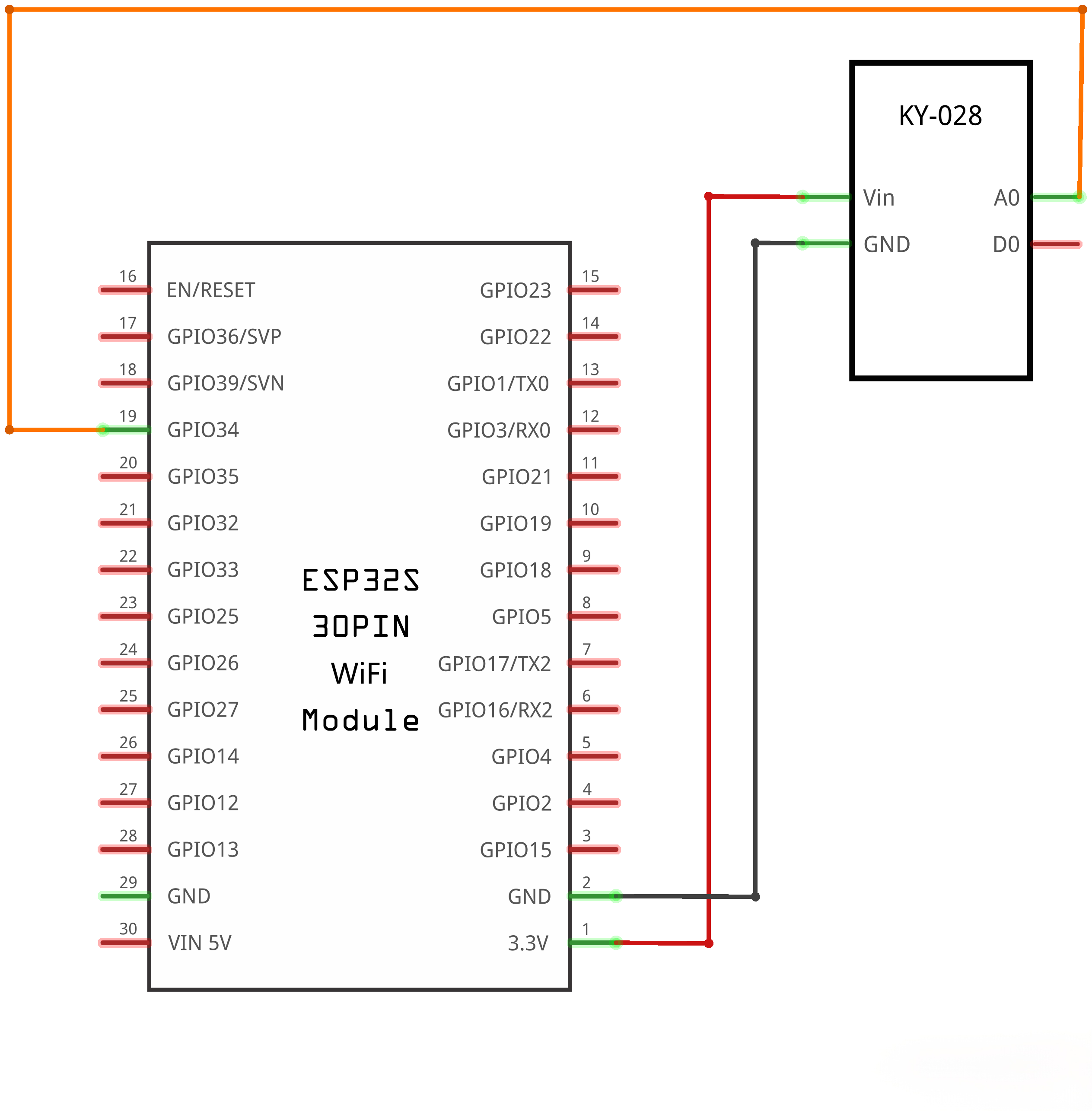
¶ Connection Schematic
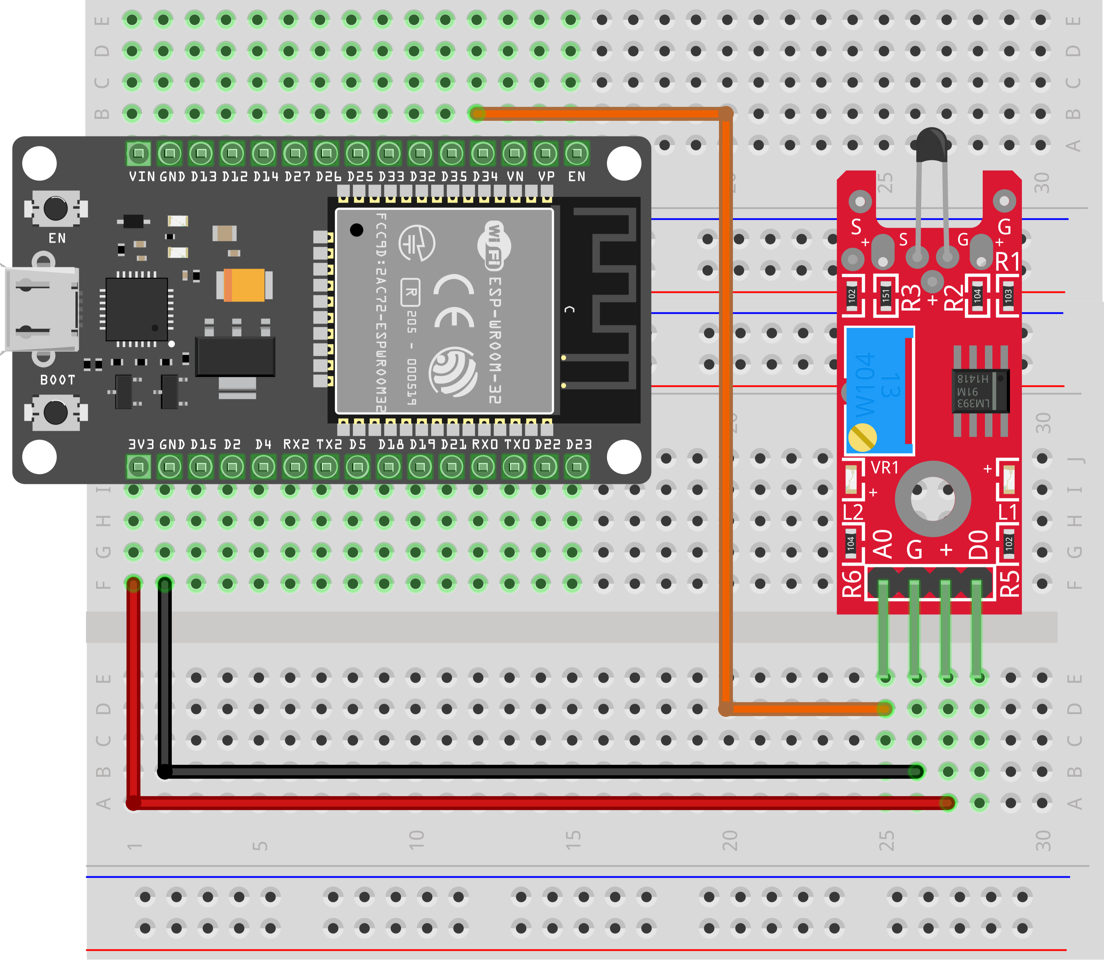
¶ Wiringdiagram
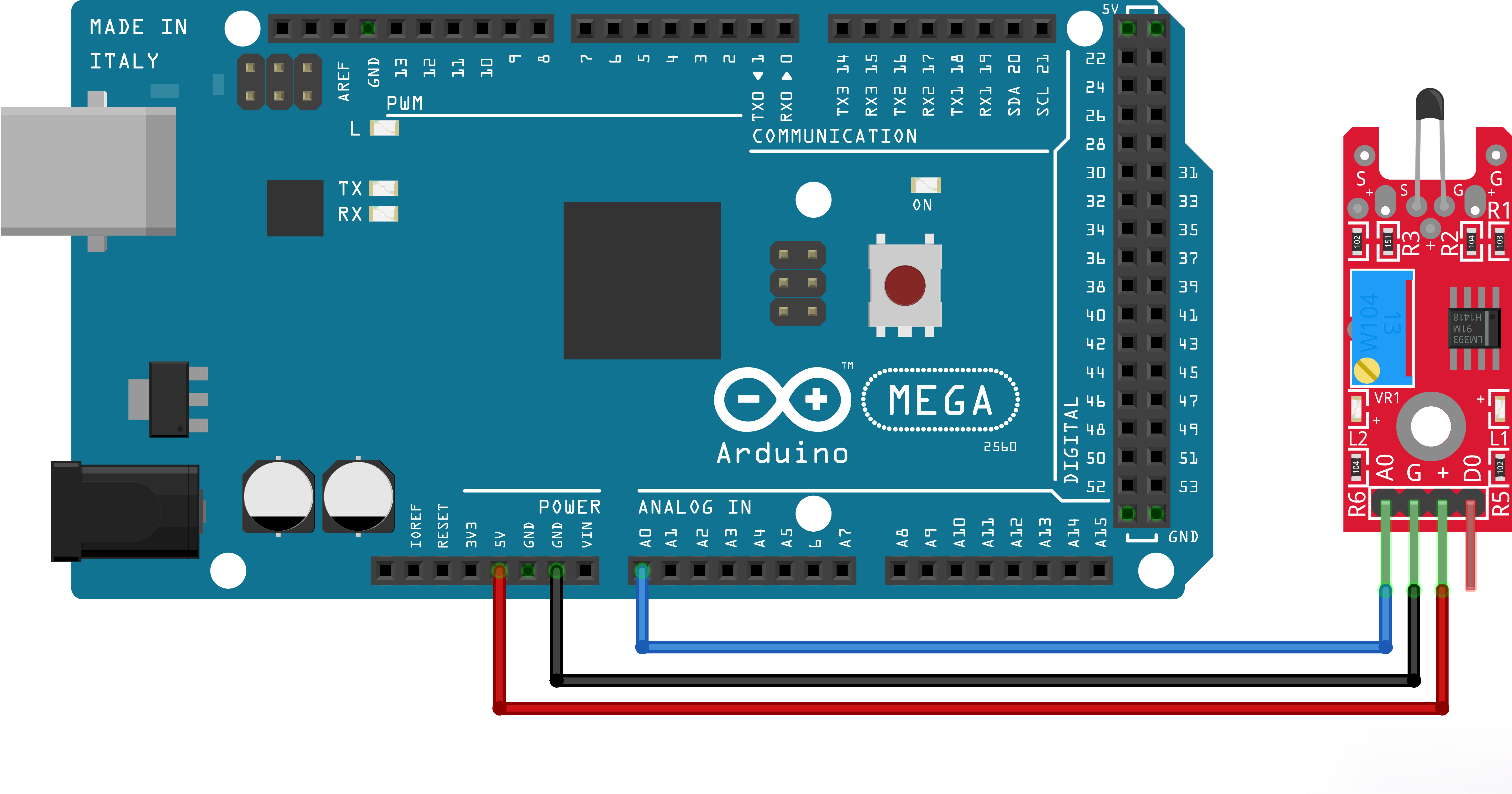

¶ Code
You can click the blue text link to download the program file to your local device, and double-click the file to open it after the download is complete. Please note: Before opening the file, ensure that you have installed the Arduino IDE development environment and completed the installation of relevant components such as the board support package and driver corresponding to the board.
¶ Code Explanation
#define SERIESRESISTOR 10000 // Series resistor value in ohms (10kΩ)
#define NOMINAL_RESISTANCE 10000 // Nominal resistance of NTC at 25°C (10kΩ)
#define NOMINAL_TEMPERATURE 25 // Reference temperature for nominal resistance (25°C)
#define BCOEFFICIENT 3950 // B-coefficient of the thermistor (typically 3950 for 10k NTC)
It is used to define the hardware wiring scheme and basic electrical parameters of the NTC thermistor.
#define ADC_MAX 1142.0
The ESP32 is equipped with a 12-bit ADC with a theoretical sampling range of 0~4095. However, the full-scale value cannot be obtained in this circuit. Restricted by the proportional characteristic of the internal operational amplifier circuit, the sampled value can only reach approximately 1140. If 4095 is directly used for calculation, significant deviation will occur in resistance and temperature readings.
float ADCvalue;
float Resistance;ADCvalue = analogRead(NTCPin);
Serial.print("Analoge ");
Serial.print(ADCvalue);
Serial.print(" = ");
Resistance = (ADC_MAX / ADCvalue) - 1;
Resistance = SERIESRESISTOR / Resistance;
Serial.print(Resistance);
Serial.println(" Ohm");
The analog sampling value of the pin is read via ADCvalue = analogRead(NTCPin);, and the actual resistance of the thermistor is calculated inversely using the voltage divider formula.
float steinhart;
steinhart = Resistance / NOMINAL_RESISTANCE; // (R/Ro)
steinhart = log(steinhart); // ln(R/Ro)
steinhart /= BCOEFFICIENT; // 1/B * ln(R/Ro)
steinhart += 1.0 / (NOMINAL_TEMPERATURE + 273.15); // + (1/To)
steinhart = 1.0 / steinhart; // Invert
steinhart -= 273.15; // convert to C
This code segment uses the NTC B-value formula, the first-order engineering simplified form of the Steinhart-Hart equation. It first calculates the ratio of the thermistor's current resistance to its nominal resistance at 25°C and computes the natural logarithm of this ratio. Combined with the thermistor B-coefficient and the nominal thermodynamic temperature at 25°C, the current ambient thermodynamic temperature is derived. Finally, the thermodynamic temperature value is subtracted by 273.15 to convert it to the commonly used Celsius temperature.