¶ Reed Switch Module
¶ Overview
In this experiment, we will learn how to use reed switch and mini reed switchmodule.
¶ Reed switch module
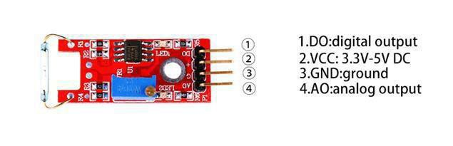
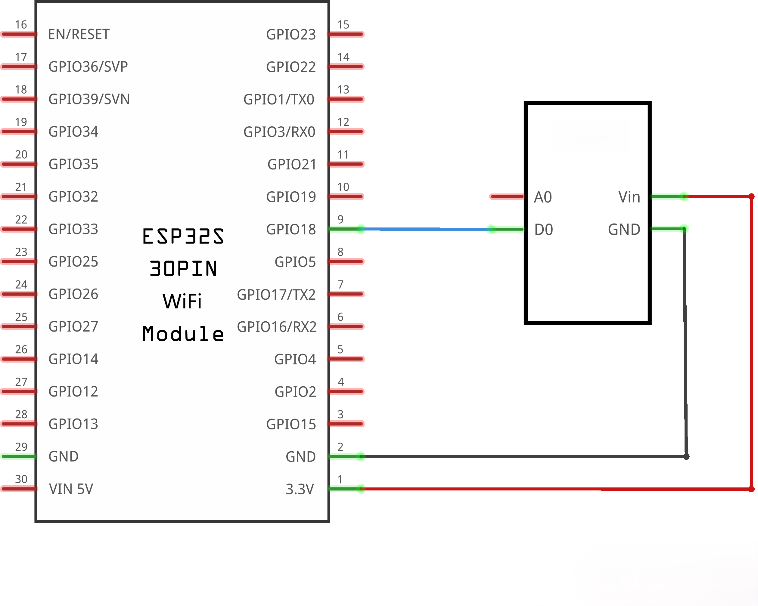
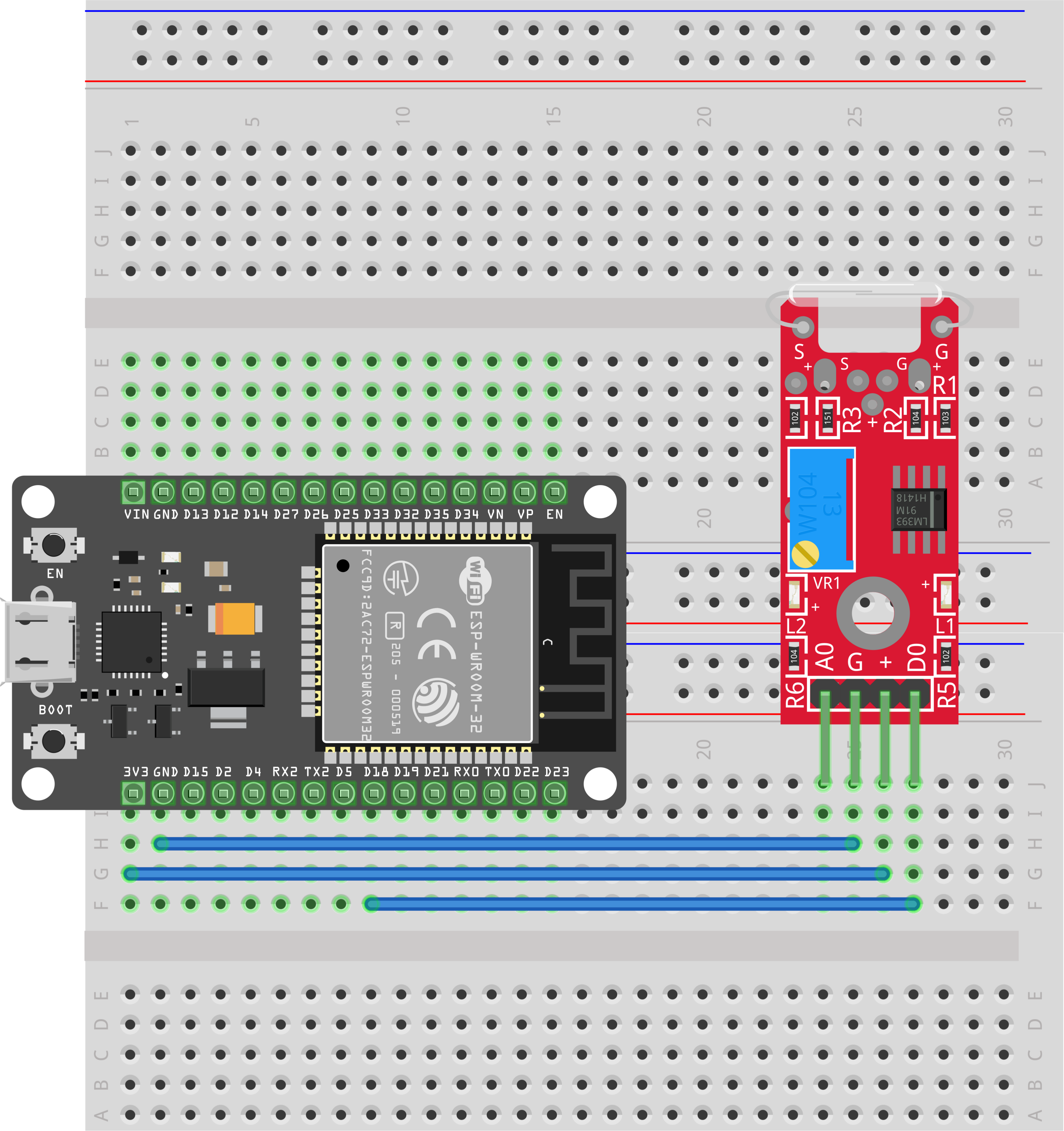
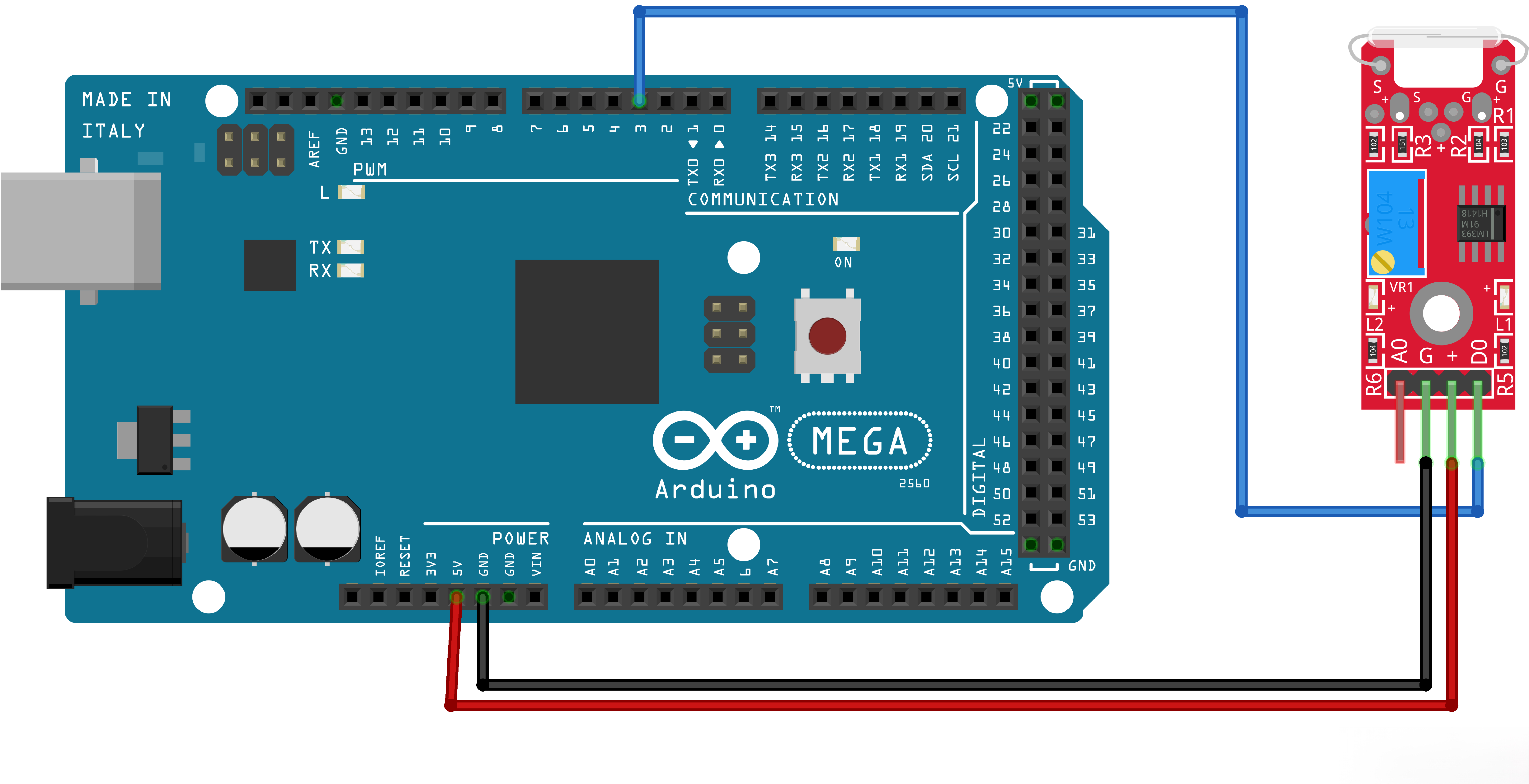
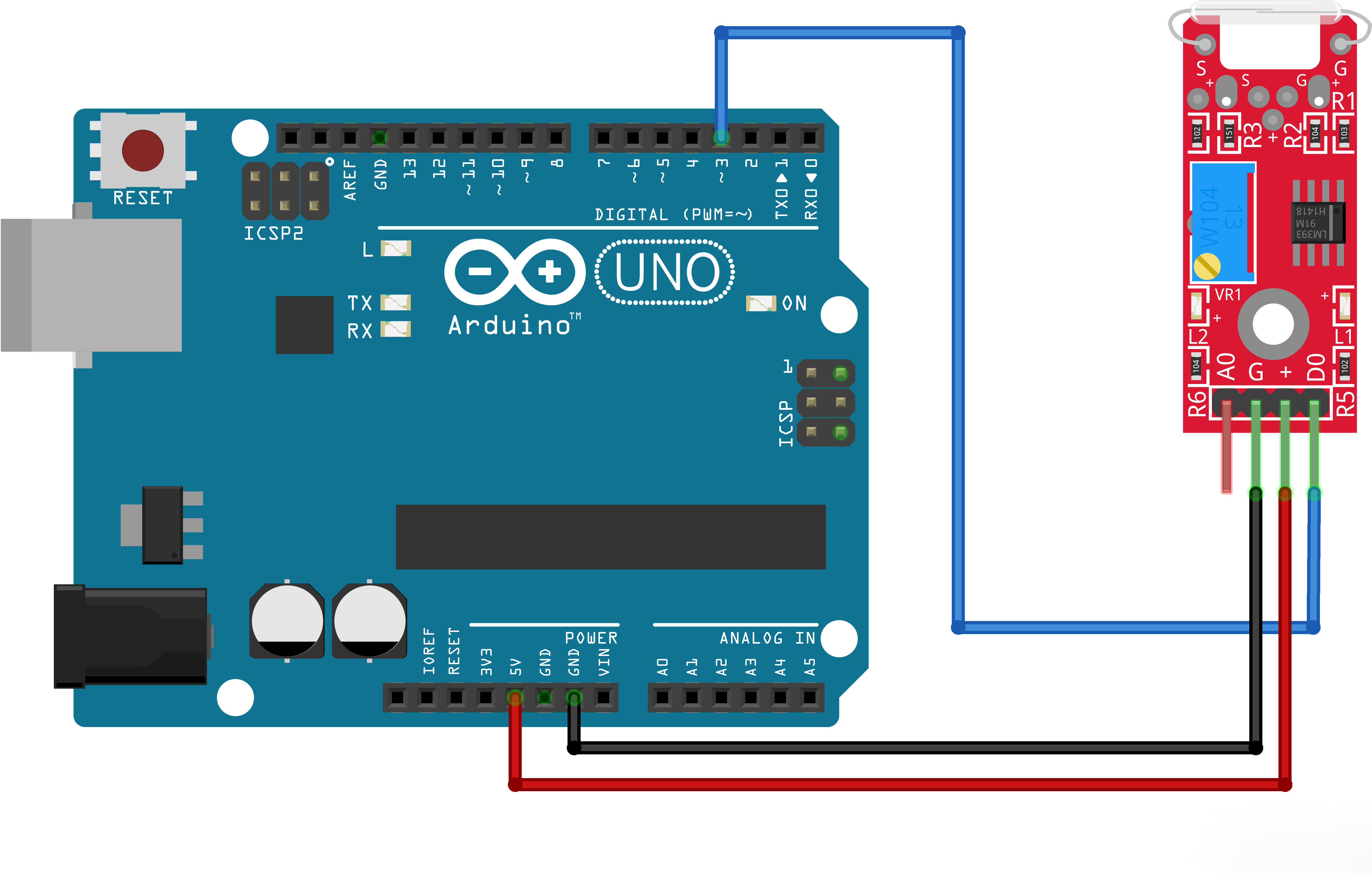
This reed switch offers an analog as well as a digital interface. The ‘G’ pen connected to GND, the ‘+’ pen to 5V DC, the ‘AO’pen offers the analog output while the ‘DO’offers the digital output. A potentiometer is used as a pull up resistor.
¶ Component Introduction
Reed Switch and Reed SensorActivation:
Although a reed switch can be activated by placing it inside an electrical coil, many reed switches and reed sensors are used for proximity sensing and are activated by a magnet. As the magnet is brought into the proximity of the reed sensor/switch, the device activates. As the magnet isremoved from the proximity of the reed sensor/switch, the device deactivates. However, the magnetic interaction involved in activating the reed switch contacts is not necessarily obvious. One wayof thinking about the interaction is that the magnet induces magnetic poles into the metal parts of the reed switch and the resulting attraction between the electrical contacts causes the reed switch to activate.
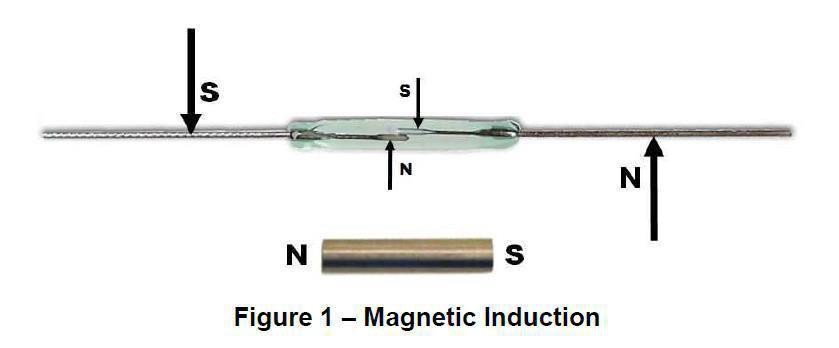
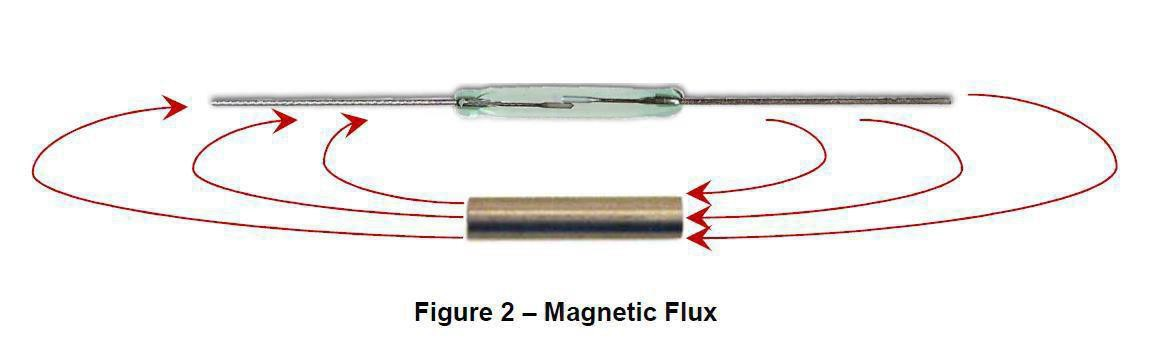
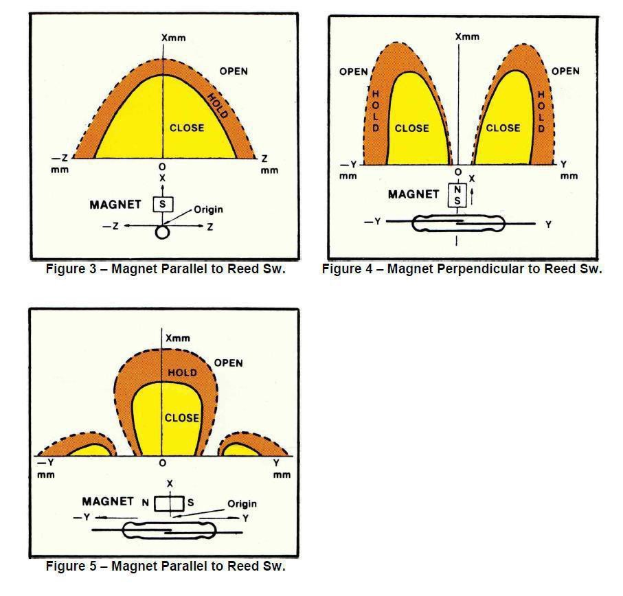
The following are examples of typical reed switch and reed sensor activate distances.
Difference between the reed switch module and mini reed switch module
As we can see, the reed switch module is bigger than the mini reed switch module. So the bigger one may have more function than the mini one. The reed switch can output in two ways: digital and analog. The mini reed can only output in digital. In the 37 sensor kit, there have 7 red pcb modules. The difference between the red and small pcb is
same asabove.
Principle
¶ Connection Schematic
¶ Wiringdiagram
¶ Code
You can click the blue text link to download the program file to your local device, and double-click the file to open it after the download is complete. Please note: Before opening the file, ensure that you have installed the Arduino IDE development environment and completed the installation of relevant components such as the board support package and driver corresponding to the board.
int sensorPin = 18; // select the input pin for the potentiometer
int ledPin = 2; // select the pin for the LED
int sensorValue = 0; // variable to store the value coming from the sensorvoid setup()
{
pinMode(ledPin,OUTPUT);
Serial.begin(9600);
}
void loop(){
sensorValue = digitalRead(sensorPin);
Serial.println(sensorValue, DEC);
if(sensorValue==HIGH){
digitalWrite(ledPin, HIGH);}
else {
digitalWrite(ledPin, LOW);
}
}
Note that the analog output from pin A0 of this sensor is not ideal, while the digital pin D0 provides highly sensitive triggering. If linear magnetic field data is required, you can use the Linear Magnetic Hall Sensor Module introduced later.