¶ Linear Magnetic Hall
¶ Overview
In this experiment, we will learn how to use the linear hallsensormodule.
¶ Linear magnetic hallsensor module
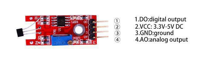
Linear Hall Sensor module to detect the presence of a magnetic field near the sensor. Variables such as field strength, polarity and position of the magnet relative to the sensor will affect point at which the ‘DO’ output switches to a high level (i.e. active high). The circuit sensitivity can be adjusted with a pot. An analog output signal from the sensor is available at pin ‘AO’.
¶ Component Introduction
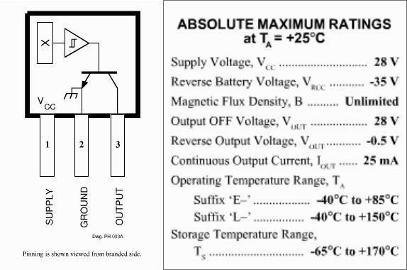
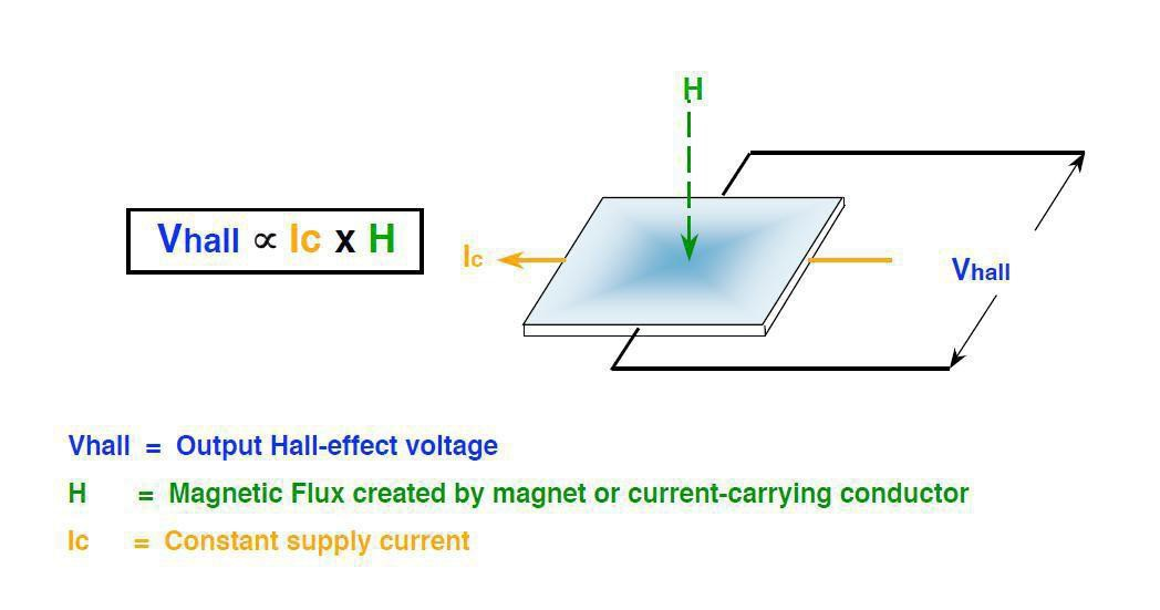
Hall Sensor:
Design Factors – MagneticTypes
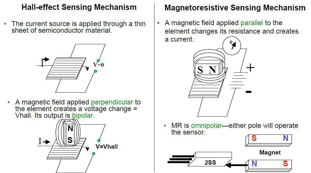
Unipolar: Only a south pole will operate the sensor. The sensor turnson with the south pole(+) and off when the south pole is removed.
Bipolar: Sensor output is pole-dependent. A south pole (+) is designedto activate the sensor; a north pole(-) is designed to deactivate. It’spossible that the sensor could turn off and still be within a positive Gauss level.
Latching: Specifications are tighter on latching. Sometimes it isdesigned to make certain that when the south pole(+) isremoved from the sensor,it will stay on until it sees the opposite pole(-).
Omni polar: The sensor is designed to operate with Radiometric linear: Output is proportional to magnetic field strength. Output sensitivity range is 2.5 – 3.75 mV per unit of Gauss.
¶ Connection Schematic
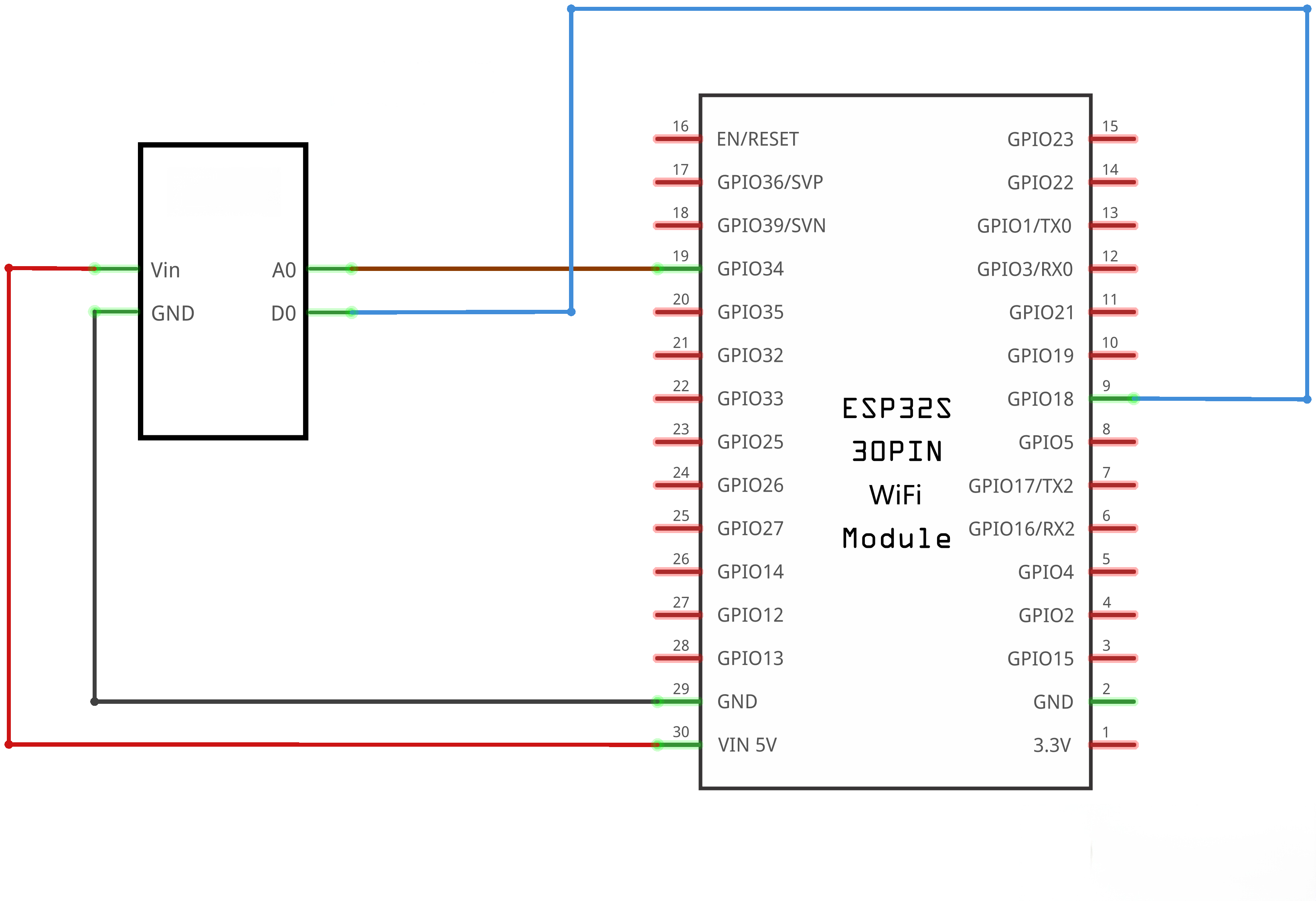
¶ Wiringdiagram
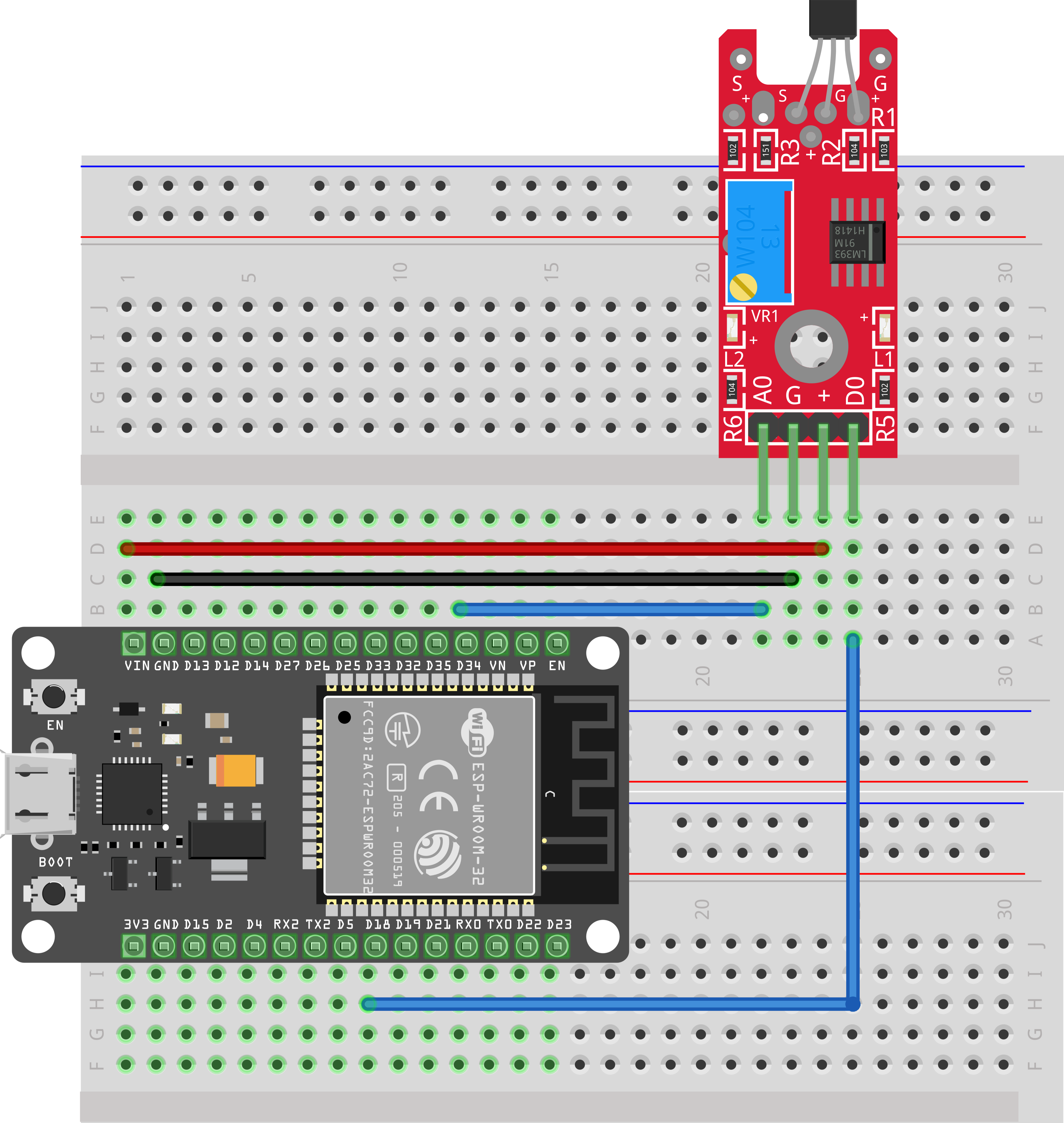
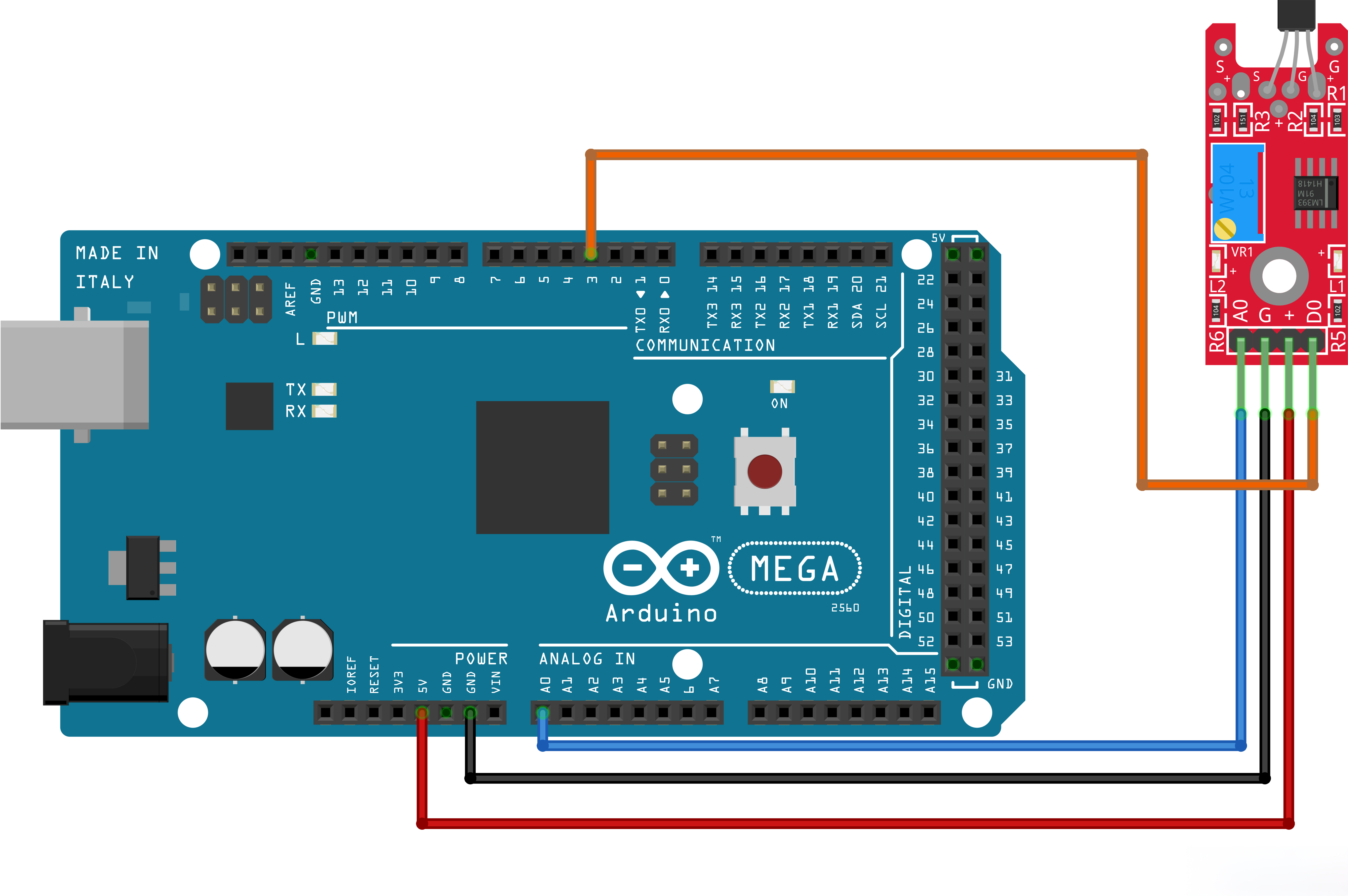
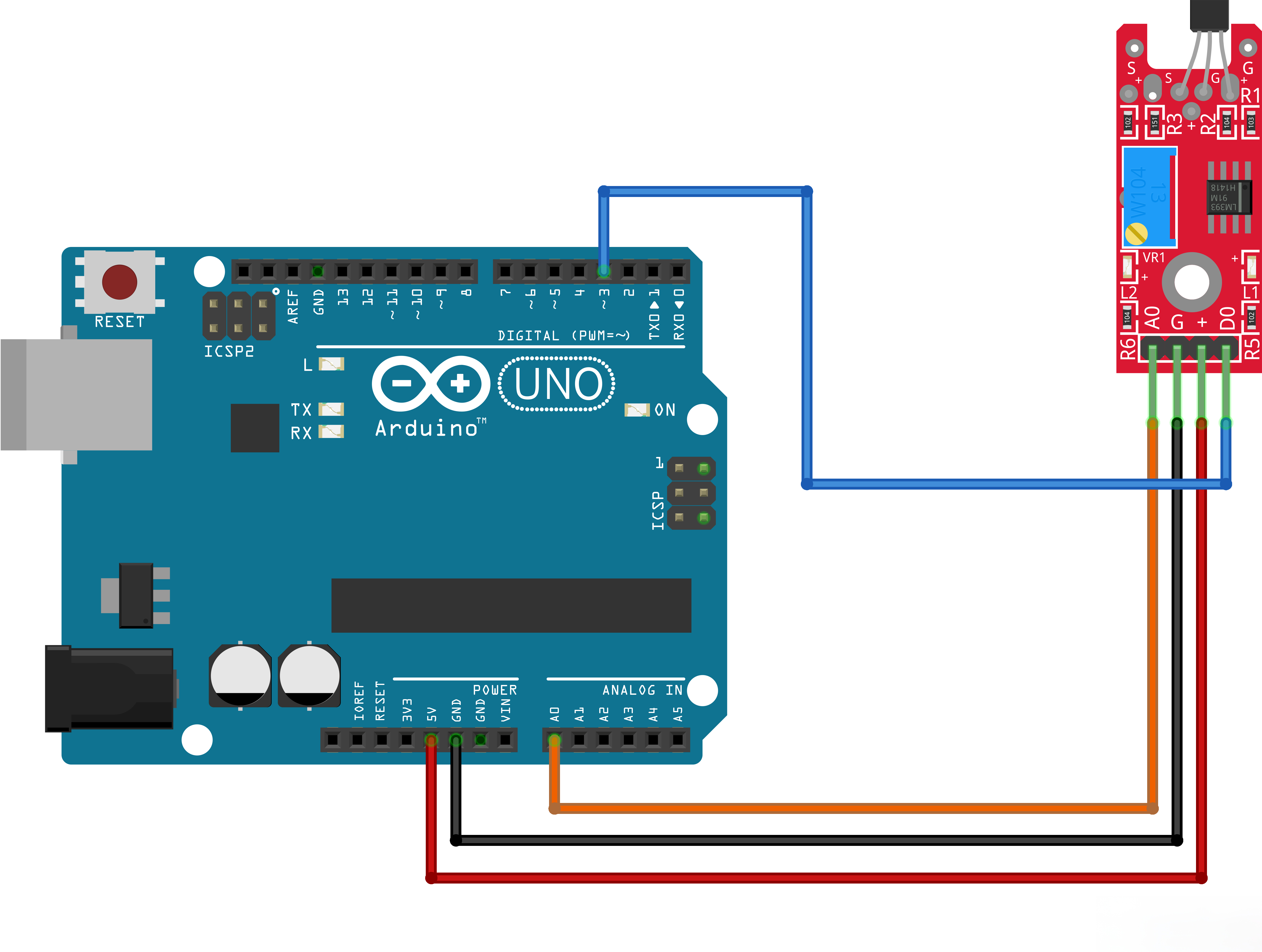
¶ Code
You can click the blue text link to download the program file to your local device, and double-click the file to open it after the download is complete. Please note: Before opening the file, ensure that you have installed the Arduino IDE development environment and completed the installation of relevant components such as the board support package and driver corresponding to the board.
int sensorPin = 34; // select the input pin for the potentiometer
int ledPin = 2; // select the pin for the LED
int sensorValue = 0; // variable to store the value coming from the sensorvoid setup()
{
pinMode(ledPin,OUTPUT);
Serial.begin(9600);
}
void loop(){
sensorValue = analogRead(sensorPin);
// digitalWrite(ledPin, HIGH);
// delay(sensorValue);
// digitalWrite(ledPin, LOW);
// delay(sensorValue);
Serial.println(sensorValue, DEC);
}
Note that this sensor outputs a fixed baseline value under normal conditions without external magnetic fields. The typical baseline reading is around 500 for UNO series boards, while it is approximately 2000 when connected to ESP32 with a 3.3V power supply.
The ADC of ESP32 has an input range of 0~3.3V, corresponding to a digital value range from 0 to 4095.
The theoretical midpoint voltage is half of the supply voltage: 3.3V÷2=1.65V, which corresponds to an ADC reading of approximately 4095÷2≈2048.
When no magnetic field is applied to the linear Hall sensor, it outputs a default voltage of 1.65V, so the ideal no-load ADC reading is 2048. The output voltage and ADC value will decrease when approaching the N pole, while they will rise when close to the S pole.