¶ RC522 RFID
¶ Overview
In this lesson, you will learn how to apply the RC522 RFID Reader Module on UNO R3. This module uses the Serial Peripheral Interface (SPI) bus to communicate with controllers such as Arduino, Raspberry Pi, beagle board, etc.
¶ Component Required:
(1) x Elegoo Uno R3
(1) x RC522 RFID module
(7) x F-M wires (Female to Male DuPont wires)
(1) x 830 Tie Points Breadboard
¶ Component Introduction
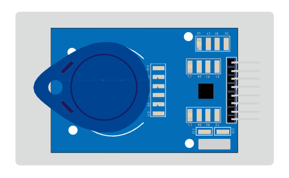
¶ RC522
The MFRC522 is a highly integrated reader/writer for contactless communication at
13.56 MHz. The MFRC522 reader supports ISO 14443A / MIFARE® mode.
The MFRC522’s internal transmitter part is able to drive a reader/writer antenna designed to communicate with ISO/IEC 14443A/MIFARE® cards and transponders without additional active circuitry. The receiver part provides a robust and efficient implementation of a demodulation and decoding circuitry for signals from ISO/IEC 14443A/MIFARE® compatible cards and transponders. The digital part handles the complete ISO/IEC 14443A framing and error detection (Parity & CRC).The MFRC522 supports MIFARE®Classic (e.g. MIFARE® Standard) products. The MFRC522 supports contactless communication using MIFARE® higher transfer speeds up to 848 kbit/s in both directions.
Various host interfaces are implemented:
•SPI interface
•Serial UART (similar to RS232 with voltage levels according pad voltage supply)
•I2C interface.
The figure below shows a typical circuit diagram, using a complementary antenna connection to the MFRC522.
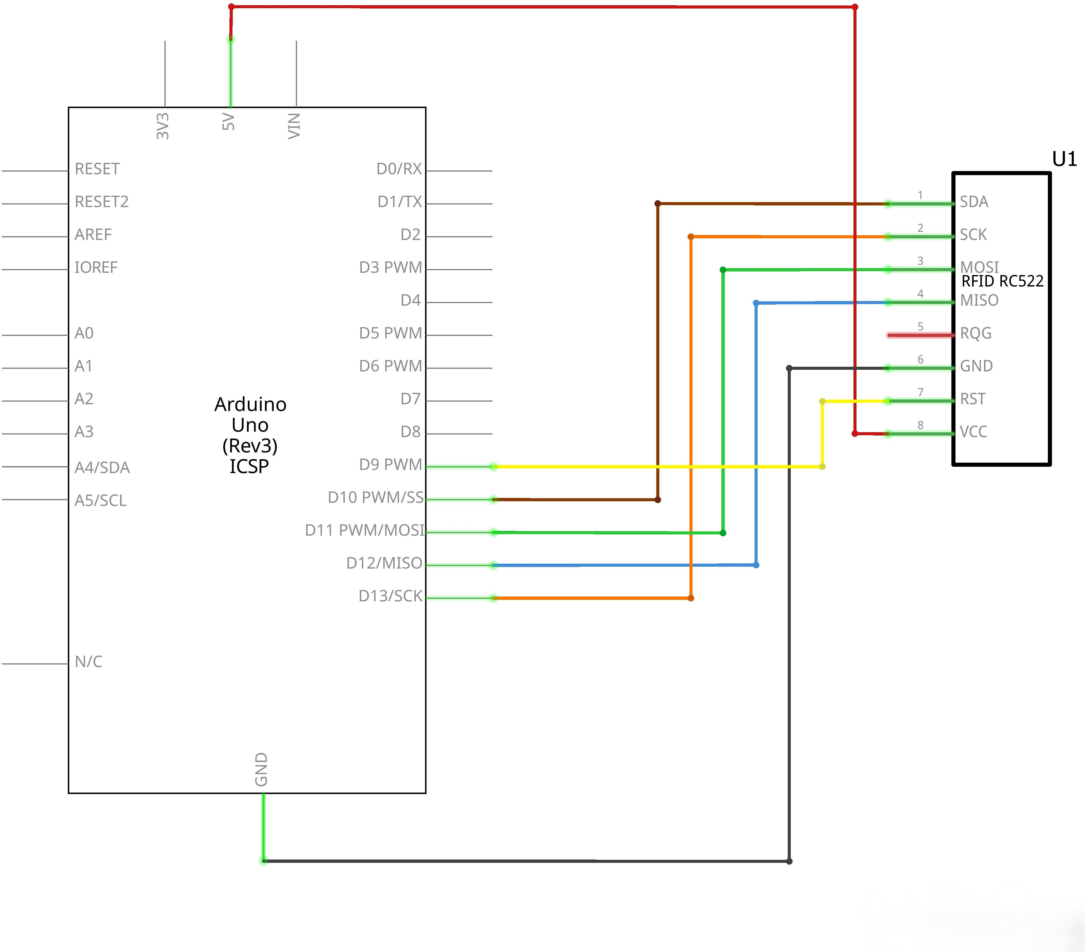
¶ Connection Schematic
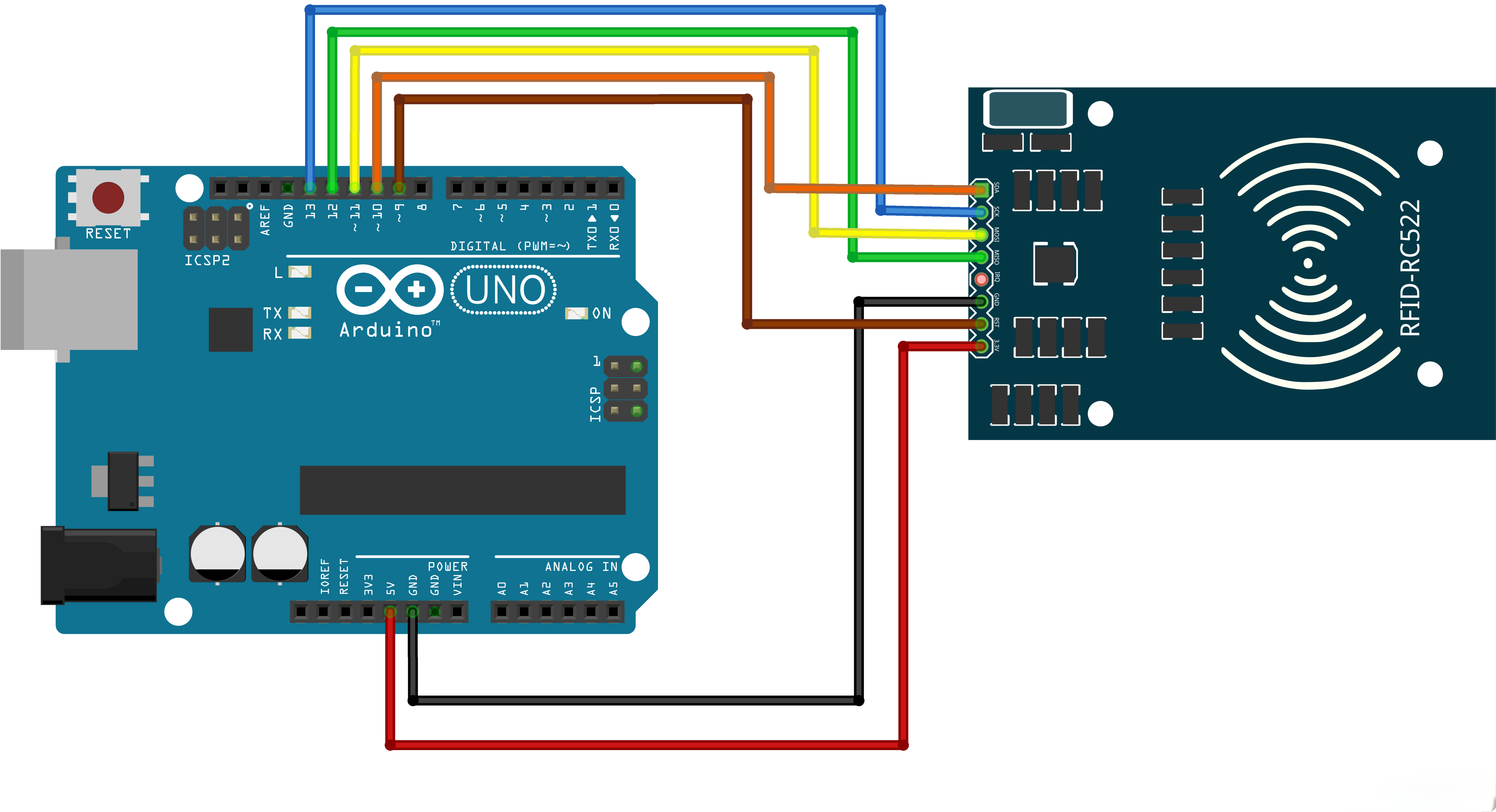
¶ Wiring diagram
¶ Code
You can click the blue text link to download the program file to your local device, and double-click the file to open it after the download is complete. Please note: Before opening the file, ensure that you have installed the Arduino IDE development environment and completed the installation of relevant components such as the board support package and driver corresponding to the UNO development board. If you have any questions about this operation process, you can refer to the "part 1" chapter of the document for detailed guidance
Before you can run this, make sure that you have installed the < rfid> library or re-install it, if necessary. Otherwise, your code won't work.
#include <SPI.h>
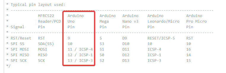
#include <MFRC522.h>#define RST_PIN 9 // Configurable, see typical pin layout above
#define SS_PIN 10 // Configurable, see typical pin layout aboveMFRC522 mfrc522(SS_PIN, RST_PIN); // Create MFRC522 instance
/* Set your new UID here! */
#define NEW_UID {0xDE, 0xAD, 0xBE, 0xEF}/MFRC522::MIFARE_Key key;
Library and Hardware Configuration:
#include <SPI.h>: Includes the SPI (Serial Peripheral Interface) library for communication#include <MFRC522.h>: Includes the MFRC522 library for RFID reader operations#define RST_PIN 5: Defines the reset pin (GPIO 5) for the MFRC522 module#define SS_PIN 21: Defines the SPI slave select pin (GPIO 21) for the MFRC522 moduleMFRC522 mfrc522(SS_PIN, RST_PIN): Creates an instance of the MFRC522 class with specified pins#define NEW_UID {0xDE, 0xAD, 0xBE, 0xEF}: Defines the new UID to be written to the card (4 bytes)MFRC522::MIFARE_Key key: Declares a MIFARE key object for authentication
RFID Technology Overview:
- MIFARE Classic: A type of RFID card that uses ISO/IEC 14443 A standard
- UID: Unique Identifier, a 4-7 byte number that uniquely identifies an RFID card
- MFRC522: A low-cost RFID reader/writer module that supports SPI communication
SPI Communication:
The MFRC522 module uses SPI (Serial Peripheral Interface) communication protocol, which requires four wires:
- SCK (Serial Clock): Generated by the master device
- MOSI (Master Out Slave In): Data sent from UNOto MFRC522
- MISO (Master In Slave Out): Data sent from MFRC522 to UNO
- SS (Slave Select): Used to select the MFRC522 module for communication
void setup() {
Serial.begin(9600); // Initialize serial communications with the PC
while (!Serial); // Do nothing if no serial port is opened (added for Arduinos based on ATMEGA32U4)
SPI.begin(); // Init SPI bus
mfrc522.PCD_Init(); // Init MFRC522 card
Serial.println(F("Warning: this example overwrites the UID of your UID changeable card, use with care!"));// Prepare key - all keys are set to FFFFFFFFFFFFh at chip delivery from the factory.
for (byte i = 0; i < 6; i++) {
key.keyByte[i] = 0xFF;
}
}
setup() Function:Initializes the system and configures the MFRC522 reader.
Serial.begin(9600): Initializes serial communication at 9600 baud rate for data outputwhile (!Serial): Waits for the serial port to be opened (useful for boards with native USB)SPI.begin(): Initializes the SPI bus for communication with the MFRC522 modulemfrc522.PCD_Init(): Initializes the MFRC522 reader moduleSerial.println(F(...)): Prints a warning message about UID modification- Key Preparation: Sets up the default factory key (0xFFFFFFFFFFFF) for MIFARE Classic cards
MIFARE Classic Keys:
- MIFARE Classic cards use 6-byte keys for authentication
- Factory default key is 0xFFFFFFFFFFFF for all sectors
- Keys are used to access and modify card data
loop() Function Overview:The main loop that continuously checks for RFID cards, displays their UID, and writes a new UID if possible.
1. Card Detection Module:
// Look for new cards, and select one if present
if ( ! mfrc522.PICC_IsNewCardPresent() || ! mfrc522.PICC_ReadCardSerial() ) {
delay(50);
return;
}
- Card Detection: Uses
PICC_IsNewCardPresent()to detect if a new card is in range - Card Selection: Uses
PICC_ReadCardSerial()to select the card and read its UID - Delay: If no card is detected, waits 50ms before checking again
2. UID Display Module:
// Dump UID
Serial.print(F("Card UID:"));
for (byte i = 0; i < mfrc522.uid.size; i++) {
Serial.print(mfrc522.uid.uidByte[i] < 0x10 ? " 0" : " ");
Serial.print(mfrc522.uid.uidByte[i], HEX);
}
Serial.println();
- UID Printing: Displays the current UID of the detected card
- Formatting: Ensures single-digit hex values are prefixed with a 0 for consistent formatting
- HEX Output: Prints UID bytes in hexadecimal format
3. UID Modification Module:
// Set new UID
byte newUid[] = NEW_UID;
if ( mfrc522.MIFARE_SetUid(newUid, (byte)4, true) ) {
Serial.println(F("Wrote new UID to card."));
}
- New UID Assignment: Creates a byte array with the new UID from the NEW_UID definition
- UID Writing: Uses
MIFARE_SetUid()to write the new UID to the card- Parameters: new UID array, UID size (4 bytes), force write flag
- Success Check: Verifies if the UID write operation was successful
4. Card Re-selection Module:
// Halt PICC and re-select it so DumpToSerial doesn't get confused
mfrc522.PICC_HaltA();
if ( ! mfrc522.PICC_IsNewCardPresent() || ! mfrc522.PICC_ReadCardSerial() ) {
return;
}
- Card Halt: Uses
PICC_HaltA()to halt the current card communication - Re-selection: Re-detects and re-selects the card to ensure proper communication
- Error Handling: Returns early if card re-selection fails
5. New UID Verification Module:
// Dump the new memory contents
Serial.println(F("New UID and contents:"));
mfrc522.PICC_DumpToSerial(&(mfrc522.uid));delay(2000);
- Memory Dump: Uses
PICC_DumpToSerial()to display the updated card information - Verification: Shows the new UID and other card data to confirm the change
- Delay: Waits 2000ms before the next iteration to prevent rapid card reading
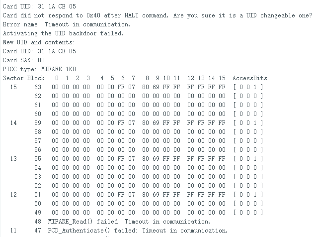
Serial Monitor Output:
- Initial message: "Warning: this example overwrites the UID of your UID changeable card, use with care!"
- When card is detected: "Card UID: XX XX XX XX"
- After UID change: "Wrote new UID to card."
- New card information: "New UID and contents:" followed by the updated UID and card data
UID Changeable Cards:
- Not all MIFARE cards can have their UID changed
- Special "UID changeable" or "magic" cards are required
- These cards have a writable UID sector that allows modification
Limitations:
- Works only with MIFARE Classic cards (Mini, 1K, 4K)
- Requires UID changeable cards
- The MFRC522 library has limited support for other RFID card types
Applications:
- Access control systems
- Inventory management
- Asset tracking
- Payment systems
- Identification and authentication