¶ Relay
In this tutorial, you will learn how to use a relay.
¶ Component Required:
(2) x 400 tie-points breadboard
(1) x Fan blade and 3-6v dc motor
(1) x L293D IC
(1) x 5v Relay
(1) x Power Supply Module
(1) x 9V1A Adapter
(15) x M-M wires (Male to Male jumper wires)
¶ Component Introduction
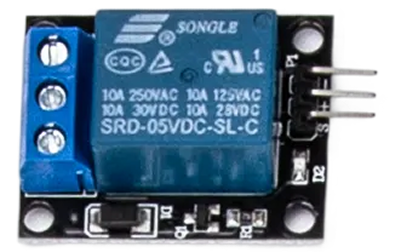
Relay:
A relay is an electrically operated switch. Many relays use an electromagnet to mechanically operate a switch, but other operating principles are also used, as in solid-state relays. Relays are used where it is necessary to control a circuit by a low- power signal (with complete electrical isolation between control and controlled circuits), or where several circuits must be controlled by one signal. The first relays were used in long-distance telegraph circuits as amplifiers. They repeated the signal coming in from one circuit and re-transmitted it on another circuit. Relays were used extensively in telephone exchanges and early computers to perform logical operations.
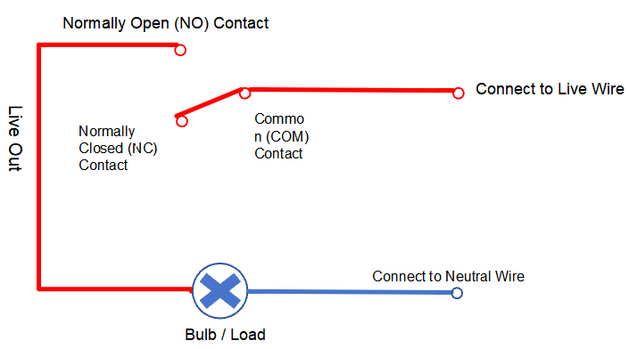
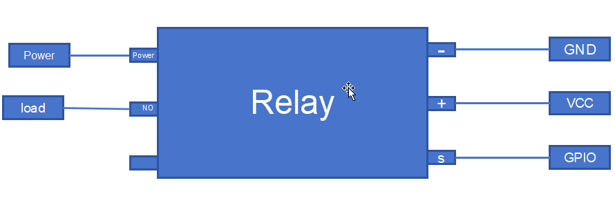
The figure below shows the pin diagram and wiring method of this relay: After the control terminal of the relay is connected to GPIO, GND and VCC, the relay will perform pull-in/release actions correspondingly when the GPIO outputs high/low level, and the bouncing sound of the internal spring can be heard during the process; if the power supply and wiring of the load terminal are normal at this time, the load will start and shut down with the action of the relay.
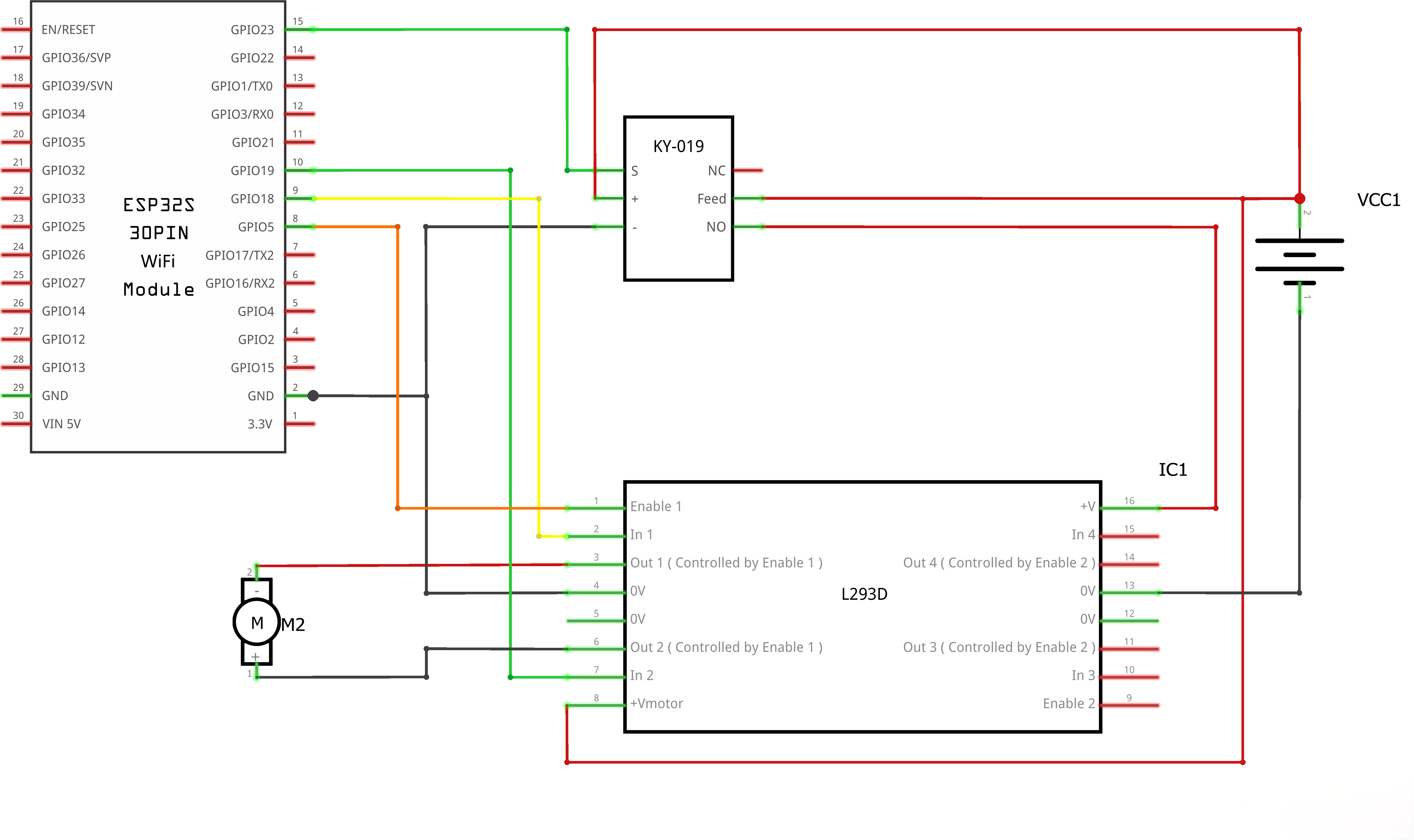
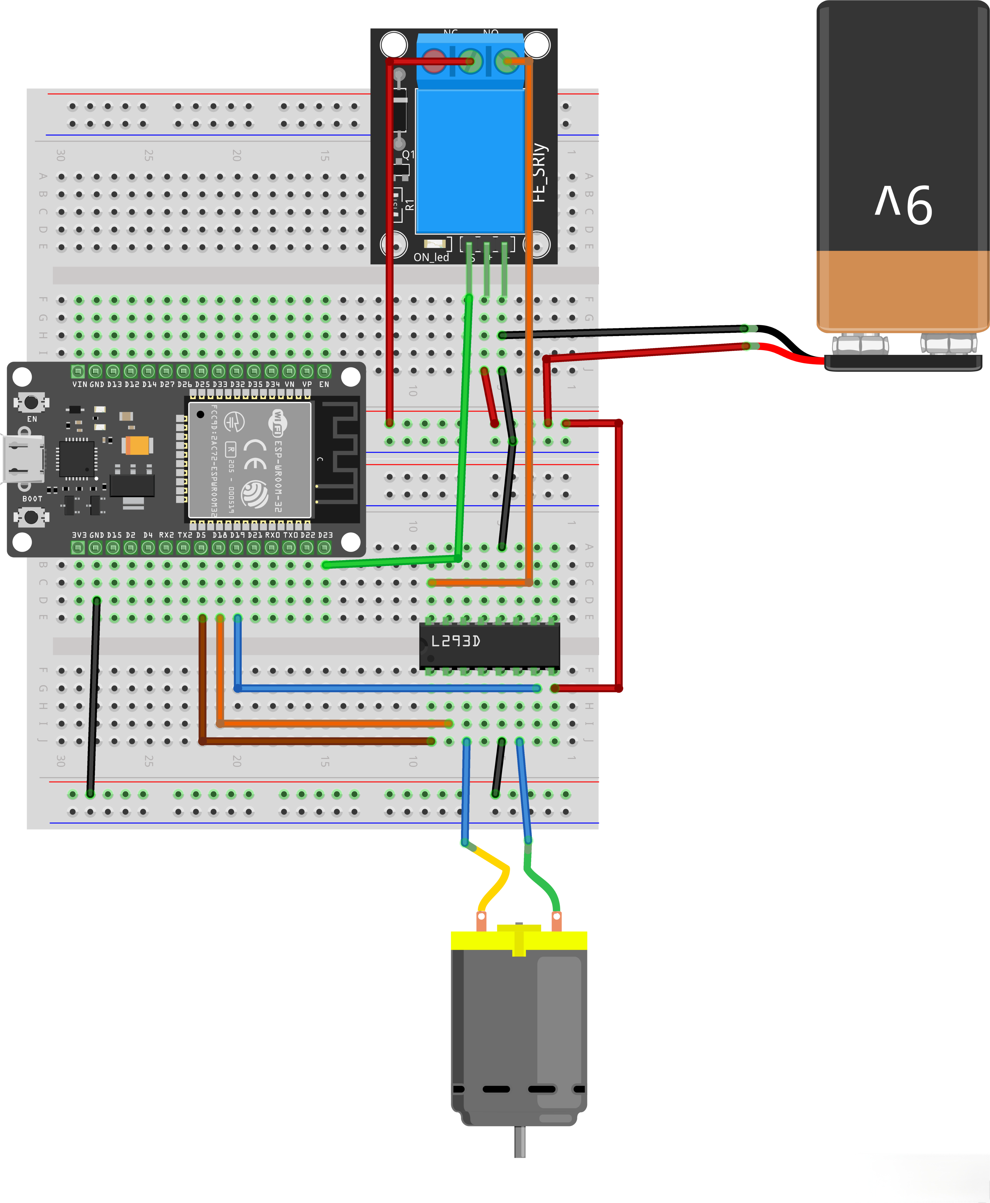
¶ Connection Schematic
¶ Wiring diagram
¶ Code
You can click the blue text link to download the program file to your local device, and double-click the file to open it after the download is complete. Please note: Before opening the file, ensure that you have installed the Arduino IDE development environment and completed the installation of relevant components such as the board support package and driver corresponding to the ESP32 development board. If you have any questions about this operation process, you can refer to the "part 1" chapter of the document for detailed guidance.
#define ENABLE 5
#define DIRA 18
#define DIRB 19
#define RELAY_PIN 23
Motor Driver Pin Definitions:
#define ENABLE 5:Pin connected to the enable pin of L293D motor driver#define DIRA 18:Pin connected to direction control A of L293D#define DIRB 19:Pin connected to direction control B of L293D#define RELAY_PIN 23:Pin connected to relay
void setup() {
//---set pin direction
pinMode(ENABLE,OUTPUT);
pinMode(DIRA,OUTPUT);
pinMode(DIRB,OUTPUT);
pinMode(RELAY_PIN,OUTPUT);
Serial.begin(9600);
}
Setup Function:
pinMode(ENABLE,OUTPUT);:Sets ENABLE pin as outputpinMode(DIRA,OUTPUT);:Sets DIRA pin as outputpinMode(DIRB,OUTPUT);:Sets DIRB pin as outputSerial.begin(9600);:Initializes serial communication at 9600 baud rate for debugging
void loop() {
//---back and forth example
digitalWrite(RELAY_PIN,HIGH);
Serial.println("Relay ON: L293D powered up");
Serial.println("One way, then reverse");
digitalWrite(ENABLE,HIGH); // enable on
for (i=0;i<5;i++) {
digitalWrite(DIRA,HIGH); //one way
digitalWrite(DIRB,LOW);
delay(750);
digitalWrite(DIRA,LOW); //reverse
digitalWrite(DIRB,HIGH);
delay(750);
}
digitalWrite(ENABLE,LOW); // disable
delay(3000);
for (i=0;i<5;i++) {
digitalWrite(DIRA,HIGH); //one way
digitalWrite(DIRB,LOW);
delay(750);
digitalWrite(DIRA,LOW); //reverse
digitalWrite(DIRB,HIGH);
delay(750);
}
digitalWrite(ENABLE,LOW); // disable
digitalWrite(RELAY_PIN,LOW);
Serial.println("Relay OFF: L293D power cut off");
delay(3000);
}
Loop Function:
-
digitalWrite(RELAY_PIN,HIGH);Relay Pull-in -
Serial.println("One way, then reverse");:Prints status message to serial monitor -
digitalWrite(ENABLE,HIGH);:Enables the motor driver -
First
forloop (5 iterations):digitalWrite(DIRA,HIGH); digitalWrite(DIRB,LOW);:Sets motor direction forwarddelay(750);:Runs motor forward for 750 millisecondsdigitalWrite(DIRA,LOW); digitalWrite(DIRB,HIGH);:Reverses motor directiondelay(750);:Runs motor reverse for 750 milliseconds
-
digitalWrite(ENABLE,LOW);:Disables the motor driver -
delay(3000);:Pauses for 3 seconds -
Second
forloop (5 iterations):- Same as first loop, repeats the forward/reverse cycle 5 times
-
digitalWrite(ENABLE,LOW);:Disables the motor driver -
delay(3000);:Pauses for 3 seconds before repeating the loop
¶ Troubleshooting
- Motor Not Moving:Check all wiring connections and ensure L293D is properly powered
- Motor Only Spinning One Direction:Verify DIRA and DIRB connections to the motor driver
- Motor Spinning Erratically:Ensure proper grounding and stable power supply
- No Serial Output:Check serial monitor baud rate is set to 9600
- Overheating L293D:Ensure motor current does not exceed L293D's rating (600mA per channel)