¶ Membrane Switch Module
¶ Overview
In this project, we will go over how to integrate a keyboard with an ESP32 board so that the ESP32 can read the keys being pressed by a user.
Keypads are used in all types of devices, including cell phones, fax machines, microwaves, ovens, door locks, etc. They're practically everywhere. Tons of electronic devices use them for user input.
So knowing how to connect a keypad to a microcontroller such as an ESP32 board is very valuable for building many different types of commercial products.
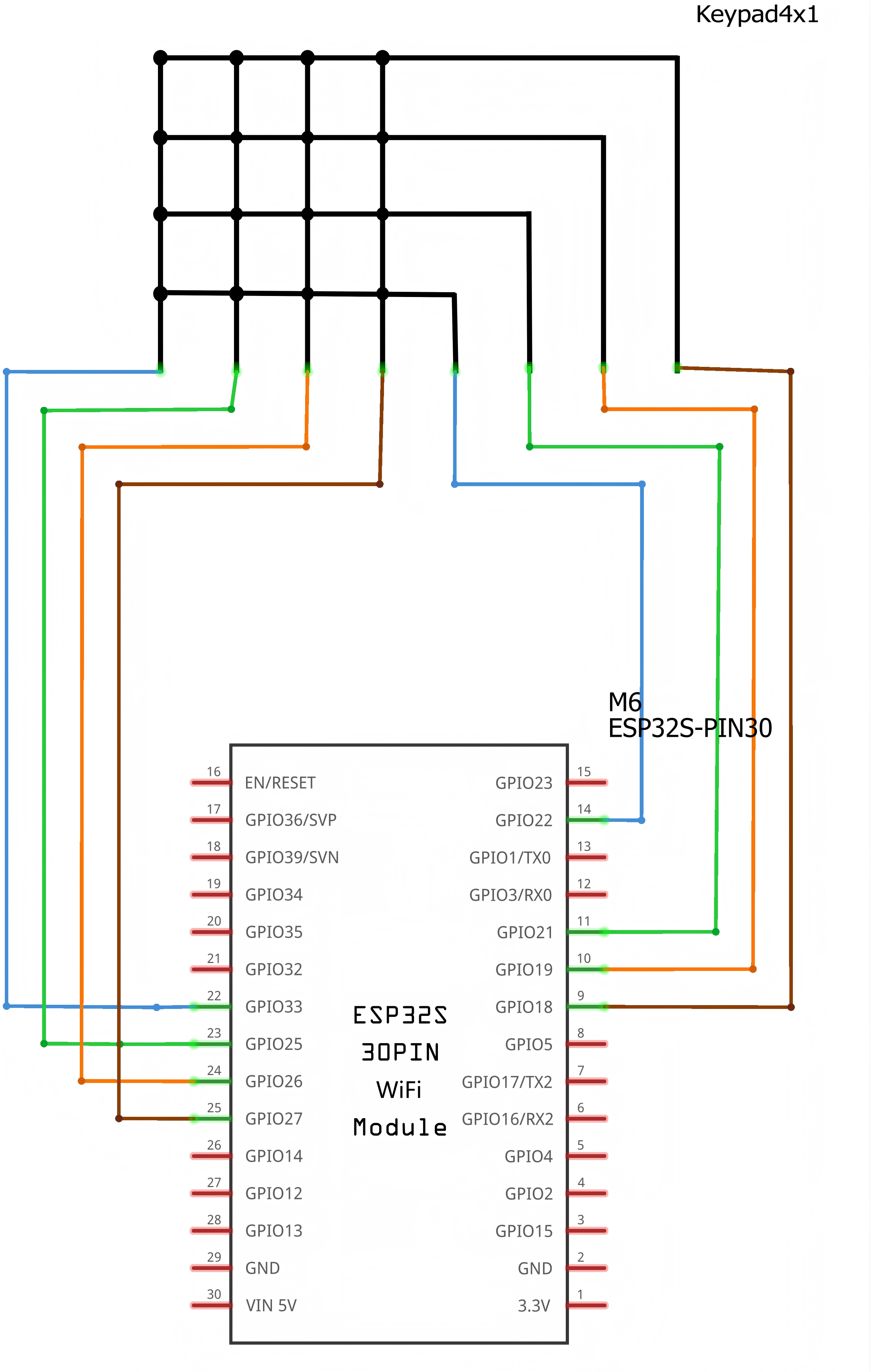
For this project, the type of keypad we will use is a matrix keypad. This is a keypad that follows an encoding scheme that allows it to have much less output pins than there are keys. For example, the matrix keypad we are using has 16 keys (0-9, A-D,*, #), yet only 8 output pins. With a linear keypad, there would have to be 17 output pins (one for each key and a ground pin) in order to work. The matrix encoding scheme allows for less output pins and thus much less connections that have to make for the keypad to work. In this way, they are more efficient than linear keypads, being that they have less wiring.
¶ Component Required:
(1)x Elegoo ESP32
(2) x 400 Tie Points Breadboard
(1) x Membrane switch module
(8) x M-M wires (Male to Male jumper wires)
¶ Connection Schematic
¶ Wiring diagram
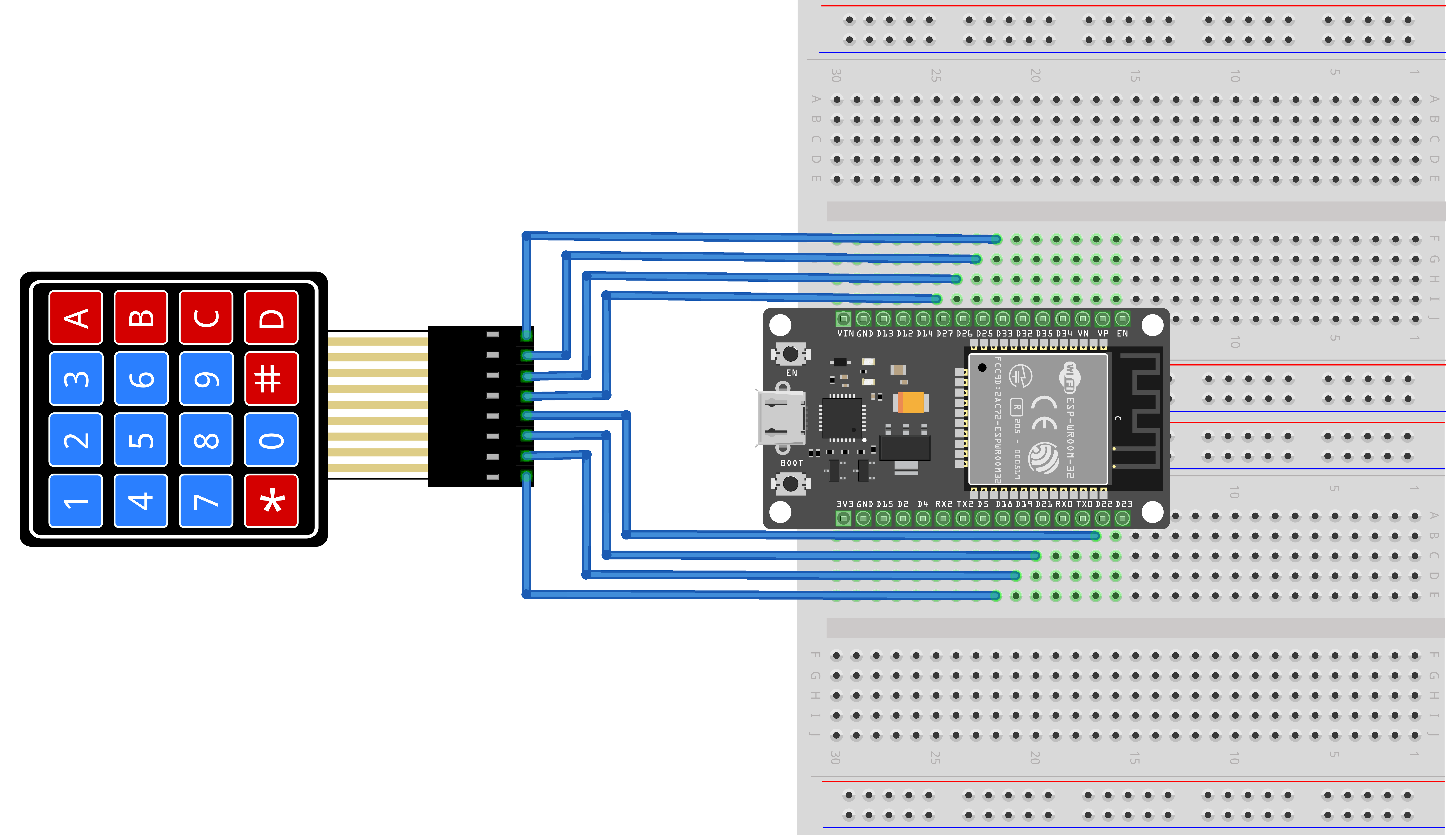
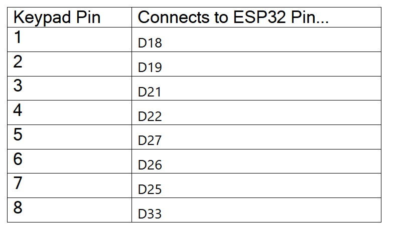
When connecting the pins to the ESP32 board, we connect them to the designated GPIO pins. We connect the first pin (the side with the * symbol) of the keypad to GPIO 18, the second pin to GPIO 19, the third pin to GPIO 21, the fourth pin to GPIO 22, the fifth pin to GPIO 27, the sixth pin to GPIO 26, the seventh pin to GPIO 25, and the eighth pin (the side with the D symbol) to GPIO 33.!!
¶ Code
You can click the blue text link to download the program file to your local device, and double-click the file to open it after the download is complete. Please note: Before opening the file, ensure that you have installed the Arduino IDE development environment and completed the installation of relevant components such as the board support package and driver corresponding to the ESP32 development board. If you have any questions about this operation process, you can refer to the "part 1" chapter of the document for detailed guidance.
With this code, once we press a key on the keypad, it should show up on the serial monitor of the Arduino software once the code is compiled and uploaded to the ESP32 board.
Click the Serial Monitor button to turn on the serial monitor. The basics about the serial monitor are introduced in details in tutorial 4 in part 2.
const byte ROWS = 4; //four rows
const byte COLS = 4; //four columns
Constant Declarations:const byte ROWS = 4 ;
Defines constants for the keypad’s dimensions (a 4x4 matrix keypad has 4 rows and 4 columns, totaling 8 pins).
Using const byte ensures these values are fixed (no accidental modification) and uses minimal memory.
char hexaKeys[ROWS][COLS] = {
{'1','2','3','A'},
{'4','5','6','B'},
{'7','8','9','C'},
{'*','0','#','D'}
};
hexaKeys[ROWS][COLS]: A 2D (two-dimensional) array that maps the physical buttons on the 4x4 keypad to their corresponding characters.
byte rowPins[ROWS] = {18, 19, 21, 22}; //connect to the row pinouts of the keypad
byte colPins[COLS] = {27,26,25,33}; //connect to the column pinouts of the keypad
- rowPins[ROWS]: An array that links the keypad’s row pins to specific ESP32 GPIO pins (e.g., the keypad’s first row pin connects to ESP32 GPIO 18).
- colPins[COLS]: An array that links the keypad’s column pins to specific ESP32 GPIO pins (e.g., the keypad’s first column pin connects to ESP32 GPIO 27).
These arrays tell the Keypad library which ESP32 pins are used to communicate with the keypad.
Keypad customKeypad = Keypad( makeKeymap(hexaKeys), rowPins, colPins, ROWS, COLS);
Keypad customKeypad: Creates a Keypad object named customKeypad (an instance of the Keypad class) to control the physical keypad.
void loop(){
char customKey = customKeypad.getKey();if (customKey){
Serial.println(customKey);
}
}
char customKey = customKeypad.getKey(): Checks if a keypad button is pressed. Returns the corresponding character (from hexaKeys) if a button is pressed; returns 0 (no value) if no button is pressed.