¶ HR-SR501
¶ Overview
In this lesson you will learn how to use a PIR movement detector with an ESP32.
The ESP32 is the heart of this project. It 'listens' to the PIR sensor and when motion is detected, instructs the LED to light on or shut off.
¶ Component Required:
(1)x Elegoo ESP32
(2) x 400 Tie Points Breadboard
(1) x HC-SR501 PIR motion sensor
(3) x F-M wires (FeMale to Male DuPont wires)
¶ Component Introduction
¶ PIR SENSOR:
PIR sensors are more complicated than many of the other sensors explained in tutorial (like photocells, FSRs and tilt switches) because there are multiple variables that affect the sensors input and output.
The PIR sensor itself has two slots. Each slot is made of a special material that is sensitive to IR. The lens used here is not really doing much and so we see that the two slots can 'see' out past some distance (basically the sensitivity of the sensor).
When the sensor is idle, both slots detect the same amount of IR, the ambient amount radiated from the room or walls or outdoors.
When a warm body like a human or an animal passes by, it first intercepts one half of the PIR sensor, which causes a positive differential change between the two halves. When the warm body leaves the sensing area, the reverse happens, whereby the sensor generates a negative differential change.
These change pulses are what is detected.
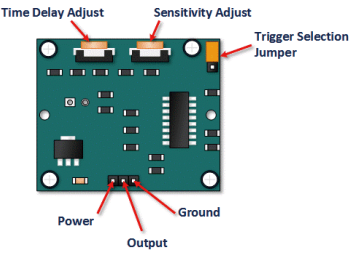
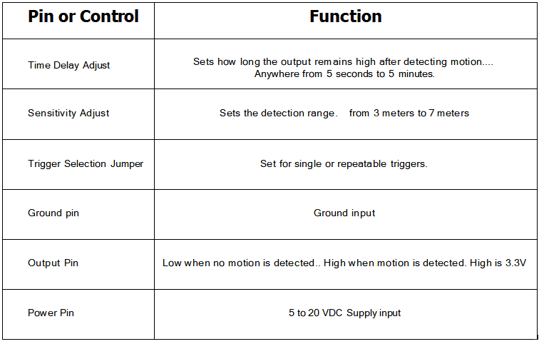
¶ HC SR501 PIR Functional Description
The SR501 will detect infrared changes and if interpreted as motion, will set its output low. What is or is not interpreted as motion is largely dependented on user settings and adjustments.
¶ Device Initialization
The device requires nearly a minute to initialize. During this period, it can and often will output false detection signals. Circuit or controller logic needs to take this initialization period into consideration.
¶ Device Area of Detection
The device will detect motion inside a 110 degree cone with a range of 3 to 7 meters.
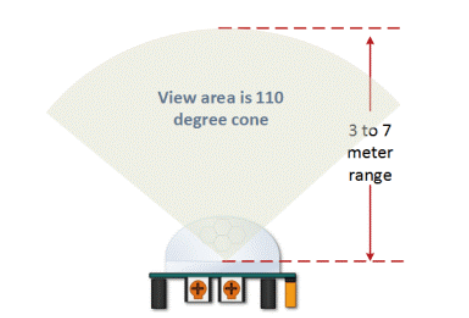
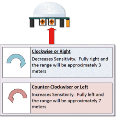
¶ HC SR501 View Area
PIR Range (Sensitivity) Adjustment
As mentioned, the adjustable range is from approximately 3 to 7 meters. The illustration below shows this adjustment.
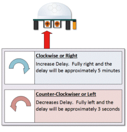
HC SR501 Sensitivity Adjust Time Delay Adjustment
The time delay adjustment determines how long the output of the PIR sensor module will remain high after detection motion. The range is from about 3 seconds to five minutes.
¶ HC SR501 Time Delay Adjustment
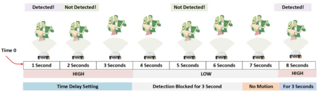
3 Seconds Off After Time Delay Completes ‒ IMPORTANT
The output of this device will go LOW (or Off) for approximately 3 seconds AFTER the time delay completes. In other words, ALL motion detection is blocked during this three second period.
¶ For Example:
Imagine you are in the single trigger mode and your time delay is set 5 seconds.
The PIR will detect motion and set it high for 5 seconds.
After five seconds, the PIR will sets its output low for about 3 seconds.
During the three seconds, the PIR will not detect motion.
After three seconds, the PIR will detect motion again and detected motion will once again set the output high.
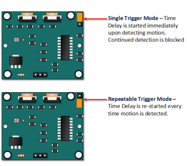
¶ Trigger Mode Selection Jumper
The trigger mode selection jumper allows you to select between single and repeatable triggers. The affect of this jumper setting is to determine when the time delay begins.
·SINGLE TRIGGER ‒ The time delay begins immediately when motion is first detected.
·REPEATABLE TRIGGER ‒ Each detected motion resets the time delay. Thus the time delay begins with the last motion detected.
¶ HC-SR501 Dance Floor Application Examples
Imagine that you want to control lighting on a dance floor based upon where the dancers are dancing.
Understanding how the time delay and trigger mode interact will be necessary to controlling that lighting in the manner that you want.
¶ Example One
In this first example, the time delay is set to three seconds and the trigger mode is set to single. As you can see in the illustration below, the motion is not always detected.
In fact, there is a period of about six seconds where motion can not be detected.
¶ Example Two
In the next example, the time delay is still at three seconds and the trigger is set to repeatable.
In the illustration below, you can see that the time delay period is restarted. However, after that three seconds, detection will still be blocked for three seconds.
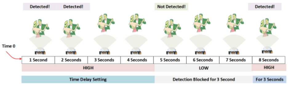
As I mentioned previously, you could override the 3 second blocking period with some creative code, but do give that consideration.Some of the electronics you use may not like an on and then off jolt. The three seconds allows for a little rest before starting back up.
¶ Connection Schematic
¶ Wiring diagram
Connecting PIR sensors to a microcontroller is really simple. The PIR acts as a digital output so all you need to do is listen for the pin to flip high (detected) or low (not detected).
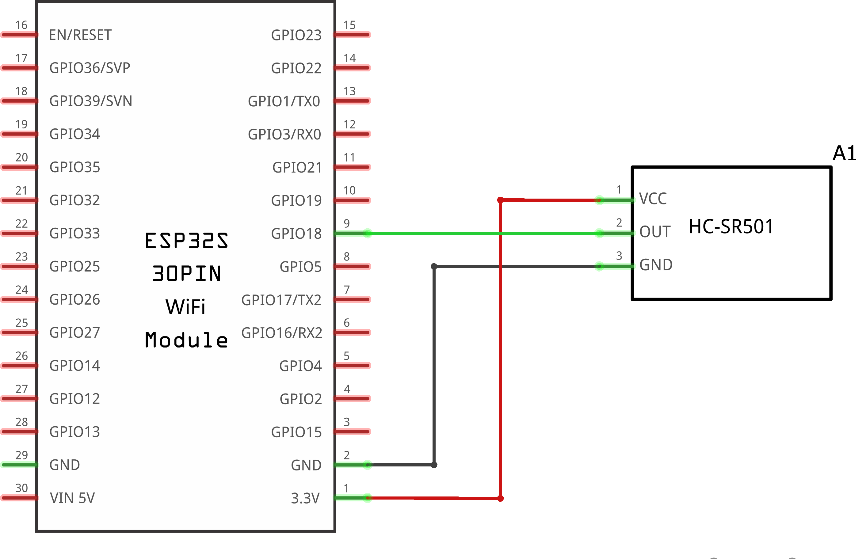
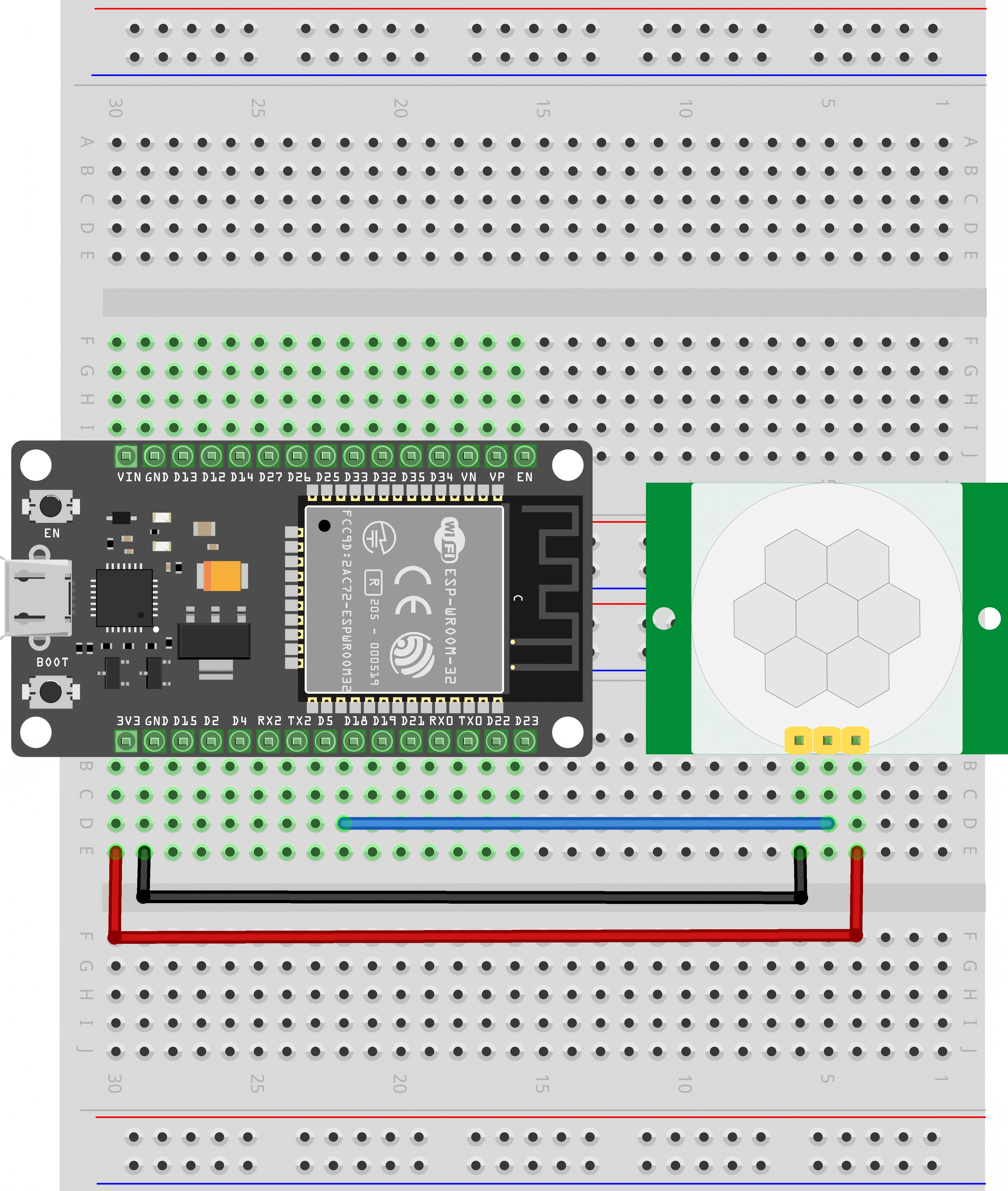
It's likely that you'll want retriggering, so be sure to put the jumper in the H position!
Power the PIR with 3.3 V and connect ground to ground. Then connect the output to a GPIO pin. In this example, we'll use D18.
¶ Code
int ledPin = 2; // LED on Pin 13 of Arduino
int pirPin = 18; // Input for HC-S501
int pirValue; // Place to store read PIR Valuevoid setup() {
pinMode(ledPin, OUTPUT);
pinMode(pirPin, INPUT);
digitalWrite(ledPin, LOW);
}
void loop() {
pirValue = digitalRead(pirPin);
digitalWrite(ledPin, pirValue);
}