¶ Gyro
¶ Overview
In this tutorial, we will learn how to use MPU-6500 module which is one of the best IMU (Inertia Measurement Unit) sensors, compatible with Arduino. IMU sensors like the MPU-6500 are used in self balancing robots, UAVs, smart phones, etc.
¶ Component Required:
(1)x Elegoo ESP32
(2) x 400 Tie Points Breadboard
(1) x MPU-6500 module
(4) x F-M wires
¶ Component Introduction
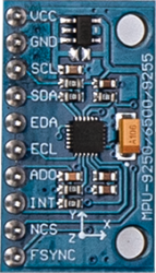
¶ MPU-6500 SENSOR
The InvenSense MPU-6500 sensor contains a MEMS accelerometer and a MEMS gyro in a single chip. It is very accurate, as it contains 16-bits analog to digital conversion hardware for each channel.
Therefore it captures the x, y, and z channel at the same time. The sensor uses the I2C-bus to interface with the Arduino.
The MPU-6500 is not expensive, especially given the fact that it combines both an accelerometer and a gyro.
IMU sensors are one of the most inevitable type of sensors used today in all kinds of electronic gadgets. They are seen in smart phones, wearables, game controllers, etc. IMU sensors help us in getting the attitude of an object, attached to the sensor in three dimensional space. These values usually in angles, thus help us to determine its attitude. Thus, they are used in smart phones to detect its orientation. And also in wearable gadgets like the nike fuel band or fit bit, which use IMU sensors to track movement.
¶ How does it work?
IMU sensors usually consist of two or more components. Listed in order of priority, they are: accelerometer, gyroscope, magnetometer and altimeter. The GY-521 is a 6 DOF (Degrees of Freedom) / six-axis IMU sensor. It outputs six readings in total: three from the accelerometer and three from the gyroscope.
The GY-521 adopts MEMS (Micro Electro Mechanical Systems) technology. The accelerometer and gyroscope are integrated into a single chip, which communicates via the I2C (Inter-Integrated Circuit) protocol.
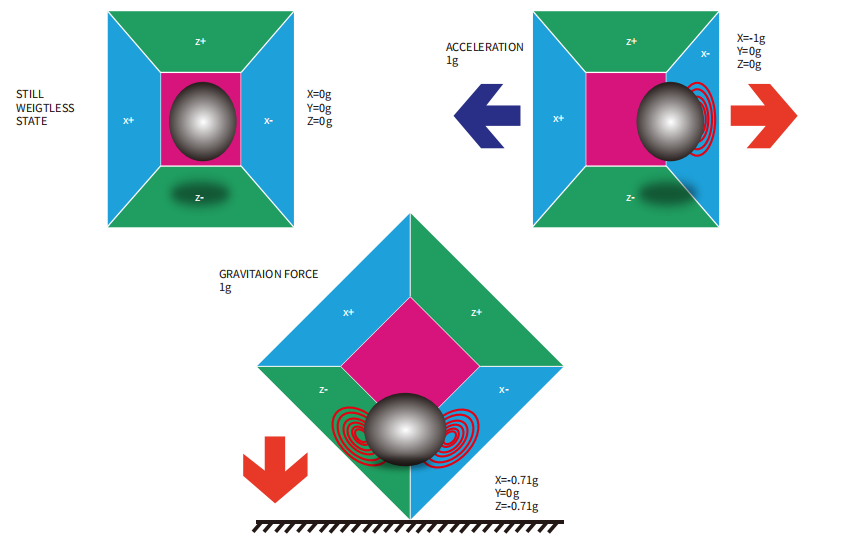
¶ How does an accelerometer work?
An accelerometer works on the principle of piezo electric effect. Here, imagine a cuboidal box, having a small ball inside it, like in the picture above. The walls of this box are made with piezo electric crystals. Whenever you tilt the box, the ball is forced to move in the direction of the inclination, due to gravity.
The wall with which the ball collides, creates tiny piezo electric currents. There are totally, three pairs of opposite walls in a cuboid. Each pair corresponds to an axis in 3D space: X, Y and Z axes. Depending on the current produced from the piezo electric walls, we can determine the direction of inclination and its magnitude. For more information check this.
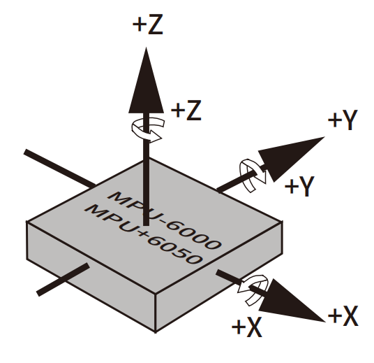
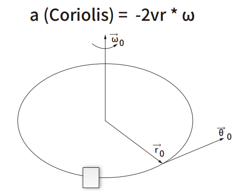
¶ How does a gyroscope work?
Gyroscopes work on the principle of Coriolis acceleration. Imagine that there is a fork- like structure, which is in constant back- and- forth motion. It is held in place using piezo electric crystals. Whenever you try to tilt this arrangement, the crystals experience a force in the direction of inclination. This is caused as a result of the inertia of the moving fork. The crystals thus produce a current in consensus with the piezo electric effect, and this current is amplified. The values are then refined by the host microcontroller.
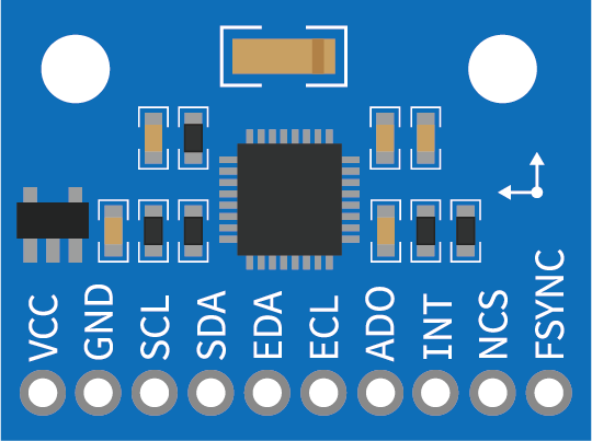
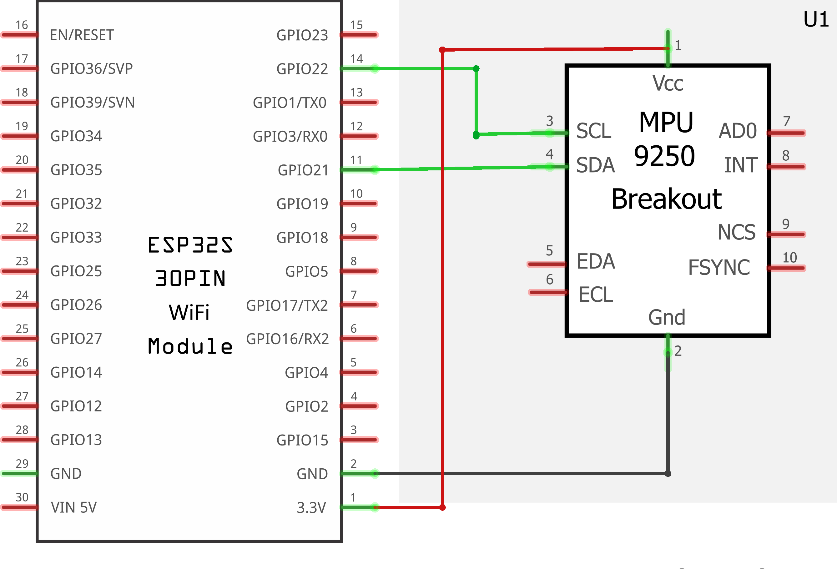
¶ Connection Schematic
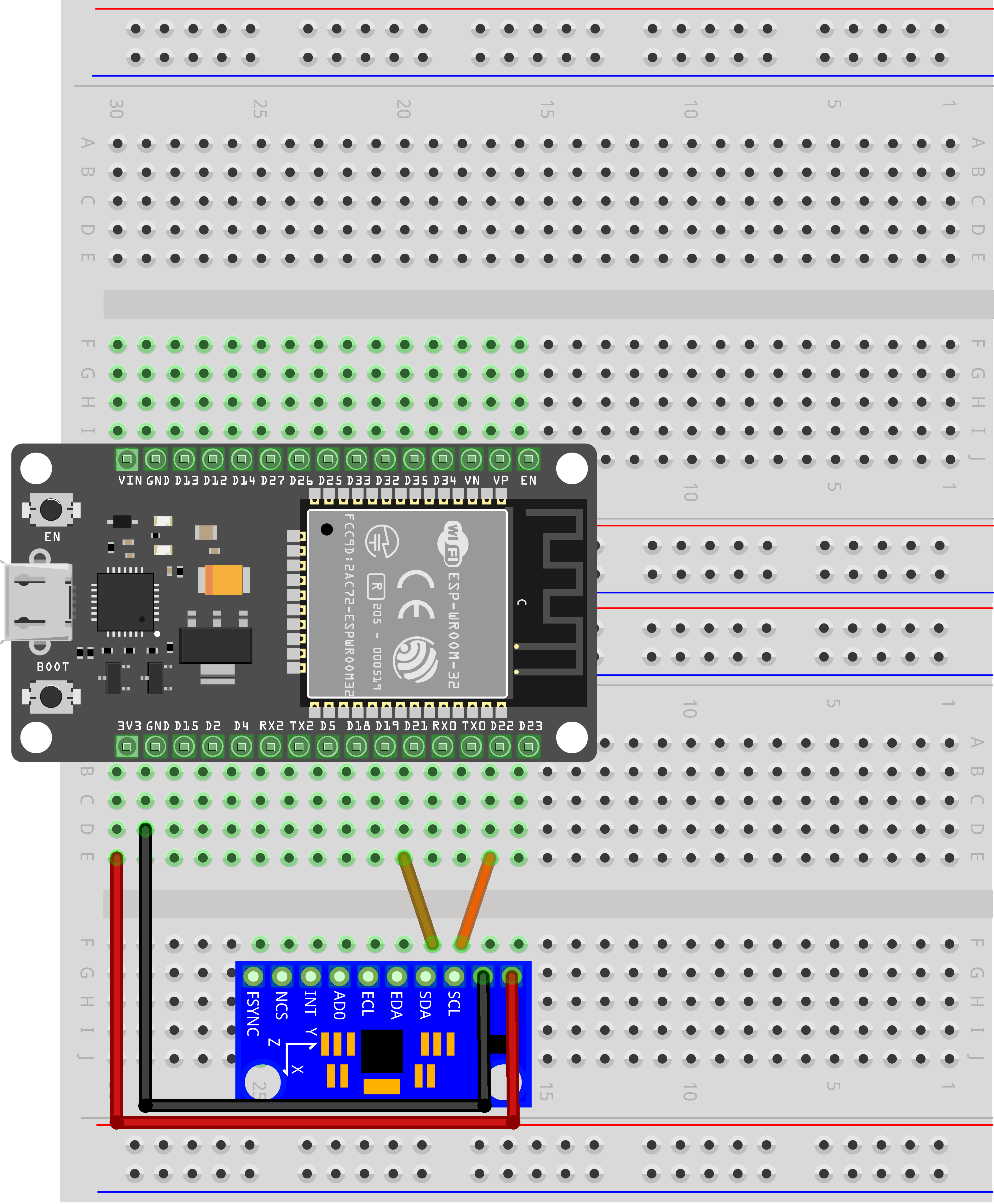
¶ Wiring diagram
¶ Code
You can click the blue text link to download the program file to your local device, and double-click the file to open it after the download is complete. Please note: Before opening the file, ensure that you have installed the Arduino IDE development environment and completed the installation of relevant components such as the board support package and driver corresponding to the ESP32 development board. If you have any questions about this operation process, you can refer to the "part 1" chapter of the document for detailed guidance mpu-6050.zip
#include<Wire.h>
const int MPU_addr=0x68; // I2C address of the MPU-6500int16_t AcX,AcY,AcZ,Tmp,GyX,GyY,GyZ;
Library and Sensor Configuration:
#include<Wire.h>: Includes the Wire library for I2C communicationconst int MPU_addr=0x68: Defines the I2C address of the MPU-6500 sensor (default address: 0x68)int16_t AcX,AcY,AcZ,Tmp,GyX,GyY,GyZ: Declares 16-bit integer variables to store sensor data:- AcX, AcY, AcZ: Accelerometer X, Y, Z axis values
- Tmp: Temperature sensor value
- GyX, GyY, GyZ: Gyroscope X, Y, Z axis values
16-bit Integer Data Type:
The int16_t type is a signed 16-bit integer that can represent values from -32768 to 32767. This is used because the MPU-6500 outputs data in 16-bit resolution, providing a good balance between precision and memory usage.
I2C Communication:
The MPU-6500 uses I2C (Inter-Integrated Circuit) communication protocol, which allows multiple devices to communicate using just two wires (SDA for data and SCL for clock).
void setup(){
Wire.begin(21,22);
Wire.beginTransmission(MPU_addr);
Wire.write(0x6B); // PWR_MGMT_1 register
Wire.write(0); // set to zero (wakes up the MPU-6500)
Wire.endTransmission(true);
Serial.begin(9600);
}
setup() Function:Initializes the system and configures the MPU-6500 sensor.
Wire.begin(21,22): Initializes the I2C bus with SDA pin 21 and SCL pin 22 (ESP32-specific I2C pins)Wire.beginTransmission(MPU_addr): Starts communication with the MPU-6500 sensorWire.write(0x6B): Selects the PWR_MGMT_1 register (address 0x6B)Wire.write(0): Writes 0 to wake up the MPU-6500 (default is in sleep mode)Wire.endTransmission(true): Ends transmission and releases the busSerial.begin(9600): Initializes serial communication at 9600 baud rate for data output
loop() Function Overview:The main loop that continuously reads sensor data and displays it on the serial monitor. This function can be divided into several key functional modules:
1. Sensor Data Request Module:
Wire.beginTransmission(MPU_addr);
Wire.write(0x3B); // starting with register 0x3B (ACCEL_XOUT_H)
Wire.endTransmission(false);
Wire.requestFrom(MPU_addr,14,true); // request a total of 14 registers
- Initiates communication with the MPU-6500
- Selects register 0x3B (ACCEL_XOUT_H) as the starting point for data reading
- Requests 14 consecutive registers (from 0x3B to 0x48) which contain all the sensor data
- The
falseparameter inendTransmission(false)keeps the I2C bus active for subsequent communication
2. Data Reading and Assembly Module:
AcX=Wire.read()<<8|Wire.read(); // 0x3B (ACCEL_XOUT_H) & 0x3C (ACCEL_XOUT_L)
AcY=Wire.read()<<8|Wire.read(); // 0x3D (ACCEL_YOUT_H) & 0x3E (ACCEL_YOUT_L)
AcZ=Wire.read()<<8|Wire.read(); // 0x3F (ACCEL_ZOUT_H) & 0x40 (ACCEL_ZOUT_L)
Tmp=Wire.read()<<8|Wire.read(); // 0x41 (TEMP_OUT_H) & 0x42 (TEMP_OUT_L)
GyX=Wire.read()<<8|Wire.read(); // 0x43 (GYRO_XOUT_H) & 0x44 (GYRO_XOUT_L)
GyY=Wire.read()<<8|Wire.read(); // 0x45 (GYRO_YOUT_H) & 0x46 (GYRO_YOUT_L)
GyZ=Wire.read()<<8|Wire.read(); // 0x47 (GYRO_ZOUT_H) & 0x48 (GYRO_ZOUT_L)
- 16-bit Data Assembly: Each sensor value is stored in two 8-bit registers (high byte and low byte)
- Bitwise Operations: Uses
<<8(shift left by 8 bits) to move the high byte to the correct position, then|(bitwise OR) to combine with the low byte - Data Reading Order: Reads registers in sequence from 0x3B to 0x48, assembling each 16-bit value
3. Data Display Module:
Serial.print("AcX = "); Serial.print(AcX);
Serial.print(" | AcY = "); Serial.print(AcY);
Serial.print(" | AcZ = "); Serial.print(AcZ);
Serial.print(" | Tmp = "); Serial.print(Tmp/340.00+36.53); //From the datasheet of MPU6050, we can know the temperature formula
Serial.print(" | GyX = "); Serial.print(GyX);
Serial.print(" | GyY = "); Serial.print(GyY);
Serial.print(" | GyZ = "); Serial.println(GyZ);
- Prints all sensor values to the serial monitor in a formatted manner
- Temperature Conversion: Converts raw temperature value to Celsius using the formula from MPU-6050 datasheet: Temp(°C) = (Temp_Raw / 340) + 36.53
- Uses
Serial.print()for continuous output andSerial.println()for the final value to move to the next line
4. Delay Module:
delay(500);
- Implements a 500ms delay between each sensor reading
- Controls the sampling rate to approximately 2 samples per second
- Prevents excessive data output to the serial monitor
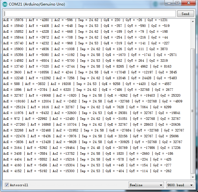
Open the monitor then you can see the data as blow:Click the Serial Monitor button to turn on the serial monitor. The basics about the serial monitor are introduced in details in part 2 Lesson 4.
MPU-6050 Register Map:
- Accelerometer: Registers 0x3B-0x40 (X, Y, Z axes)
- Temperature: Registers 0x41-0x42
- Gyroscope: Registers 0x43-0x48 (X, Y, Z axes)
Serial Monitor Output:
- Format: AcX = [value] | AcY = [value] | AcZ = [value] | Tmp = [value]°C | GyX = [value] | GyY = [value] | GyZ = [value]
- Accelerometer values: Typically range from -32768 to 32767 (raw values)
- Temperature values: Range from approximately -40°C to 85°C
- Gyroscope values: Typically range from -32768 to 32767 (raw values, representing angular velocity)
I2C Pin Configuration (ESP32):
- SDA (Data): GPIO 21
- SCL (Clock): GPIO 22
- VCC: 3.3V or 5V (MPU-6050 is compatible with both)
- GND: Ground
MPU-6050 Power Management:
- The sensor is in sleep mode by default to conserve power
- Writing 0 to register 0x6B (PWR_MGMT_1) wakes up the sensor
- The PWR_MGMT_1 register also allows for clock source selection and other power-related settings
Data Resolution:
- Accelerometer: 16-bit resolution (±2g, ±4g, ±8g, or ±16g configurable ranges)
- Gyroscope: 16-bit resolution (±250°/s, ±500°/s, ±1000°/s, or ±2000°/s configurable ranges)
- Temperature: 16-bit resolution
Calibration Considerations:
- The MPU-6050 may require calibration for accurate readings
- Accelerometer calibration involves measuring values when the sensor is stationary
- Gyroscope calibration involves measuring drift when the sensor is not rotating
- Raw values can be converted to physical units (g for acceleration, °/s for angular velocity) using scale factors from the datasheet
Applications:
- Motion tracking and gesture recognition
- Inertial navigation systems
- Tilt and orientation sensing
- Vibration analysis
- Gaming and virtual reality controllers
- Robotics and drone stabilization