¶ DC motor
¶ Overview
In this tutorial, you will learn how to control a small DC motor using an UNO and a L293D IC.
¶ Component Required:

(1) x Elegoo Uno R3
(1) x 830 tie-points breadboard
(1) x L293D IC
(1) x Fan blade and 3-6v motor
(5) x M-M wires (Male to Male jumper wires)
(1) x Power Supply Module
(1)x 9V1A adapter
¶ Component Introduction
¶ Breadboard Power Supply
The small DC motor is likely to use more power than aN UNO board digital output can handle directly. If we tried to connect the motor straight to an UNO R3 board pin, then it's likely to damage the UNO board. So we use a power supply module provides power supply.
Product Specifications:
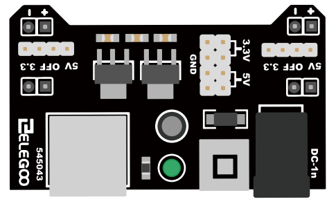
- Locking On/Off Switch
- LED Power Indicator
- Input voltage: 6.5-9v (DC) via 5.5mm x 2.1mm plug
- Output voltage: 3.3V/5v
- Maximum output current: 700 mA
- Independent control rail output. 0v, 3.3v, 5v to breadboard
- Output header pins for convenient external use
- Size: 2.1 in x 1.4 in
- USB device connector onboard to power external device
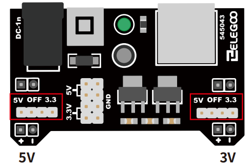
Setting up output voltage:
The left and right voltage output can be configured independently.
To select the output voltage, move jumper to the corresponding pins.
Note: power indicator LED and the breadboard power rails will not
power on if both jumpers are in the“OFF”position.
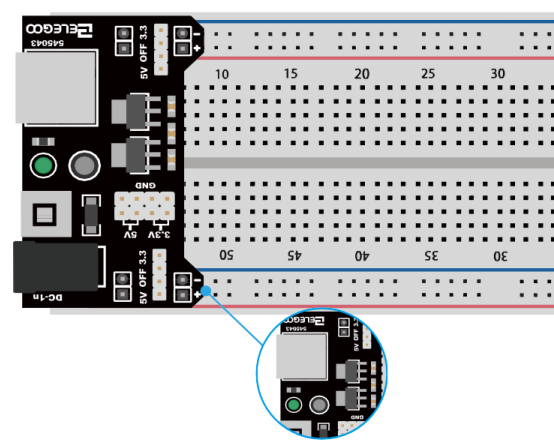
Important note:
Make sure that you align the module correctly on the breadboard. The negative pin(-) on module lines up with the blue line(-) on breadboard and that the positive pin(+) lines up with the red line(+). Failure to do so could result in you accidently reversing the power to your project.
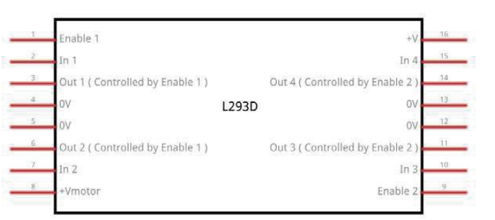
¶ L293D
This is a very useful chip. It can actually control two motors independently. We are just using half the chip in this lesson, most of the pins on the right hand side of the chip are for controlling a second motor.
Product Specifications:
•Featuring Unitrode L293 and L293D Products Now From Texas Instruments
•Wide Supply-Voltage Range: 4.5 V to 36 V
•Separate Input-Logic Supply
•Internal ESD Protection
•Thermal Shutdown
•High-Noise-Immunity Inputs
•Functionally Similar to SGS L293 and SGS L293D
•Output Current 1 A Per Channel (600 mA for L293D)
•Peak Output Current 2 A Per Channel (1.2 A for L293D)
•Output Clamp Diodes for Inductive Transient Suppression (L293D)
Description/ordering information
The L293 and L293D are quadruple high-current half-H drivers. The L293 is designed to provide bidirectional drive currents of up to 1 A at voltages from 4.5 V to 36 V. The L293D is designed to provide bidirectional drive currents of up to 600-mA at voltages from 4.5 V to 36 V. Both devices are designed to drive inductive loads such as relays, solenoids, dc and bipolar stepping motors, as well as other high-current/high-voltage loads in positive-supply applications.
All inputs are TTL compatible. Each output is a complete totem-pole drive circuit, with a Darlington transistor sink and a pseudo-Darlington source. Drivers are enabled in pairs, with drivers 1 and 2 enabled by 1,2EN and drivers 3 and 4 enabled by 3,4EN. When an enable input is high, the associated drivers are enabled, and their outputs are active and in phase with their inputs. When the enable input is low, those drivers are disabled, and their outputs are off and in the high-impedance state. With the proper data inputs, each pair of drivers forms a full-H (or bridge) reversible drive suitable for solenoid or motor applications.
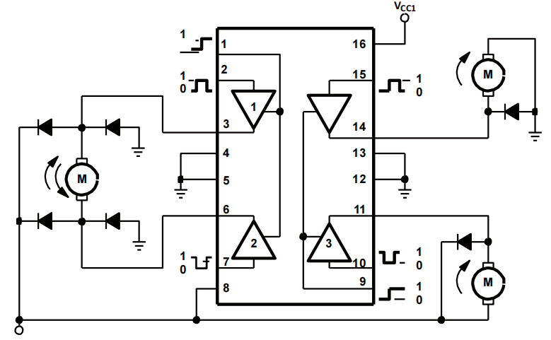
Block diagram
There are 3 wires connected to the Arduino, 2 wires connected to the motor, and 1 wire connected to a battery.
To use this pinout:
The left hand side deals with the first motor, the right hand side deals with a second motor. Yes, you can run it with only one motor connected.
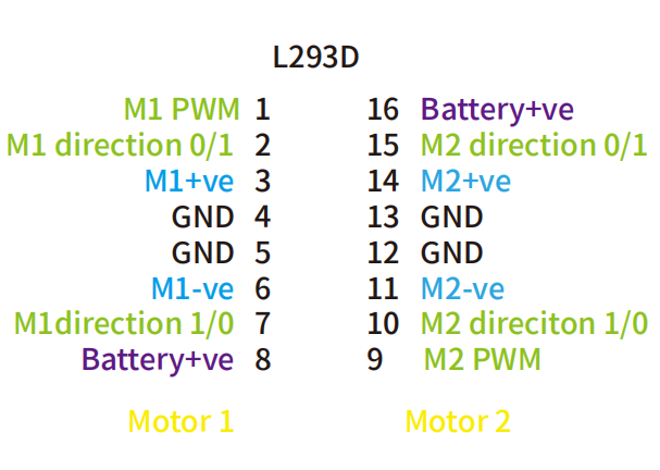
UNO Connections
M1 PWM - connect this to a PWM pin on the UNO. They're labelled on the UNO, D5 is an example. Output any integer between 0 and 255, where 0 will be off, 128 is half speed and 255 is max speed.
M1 direction 0/1 and M1 direction 1/0 - Connect these two to two GPIO pins. Output one pin as HIGH and the other pin as LOW, and the motor will spin in one direction.
Reverse the outputs to LOW and HIGH, and the motor will spin in the other direction.
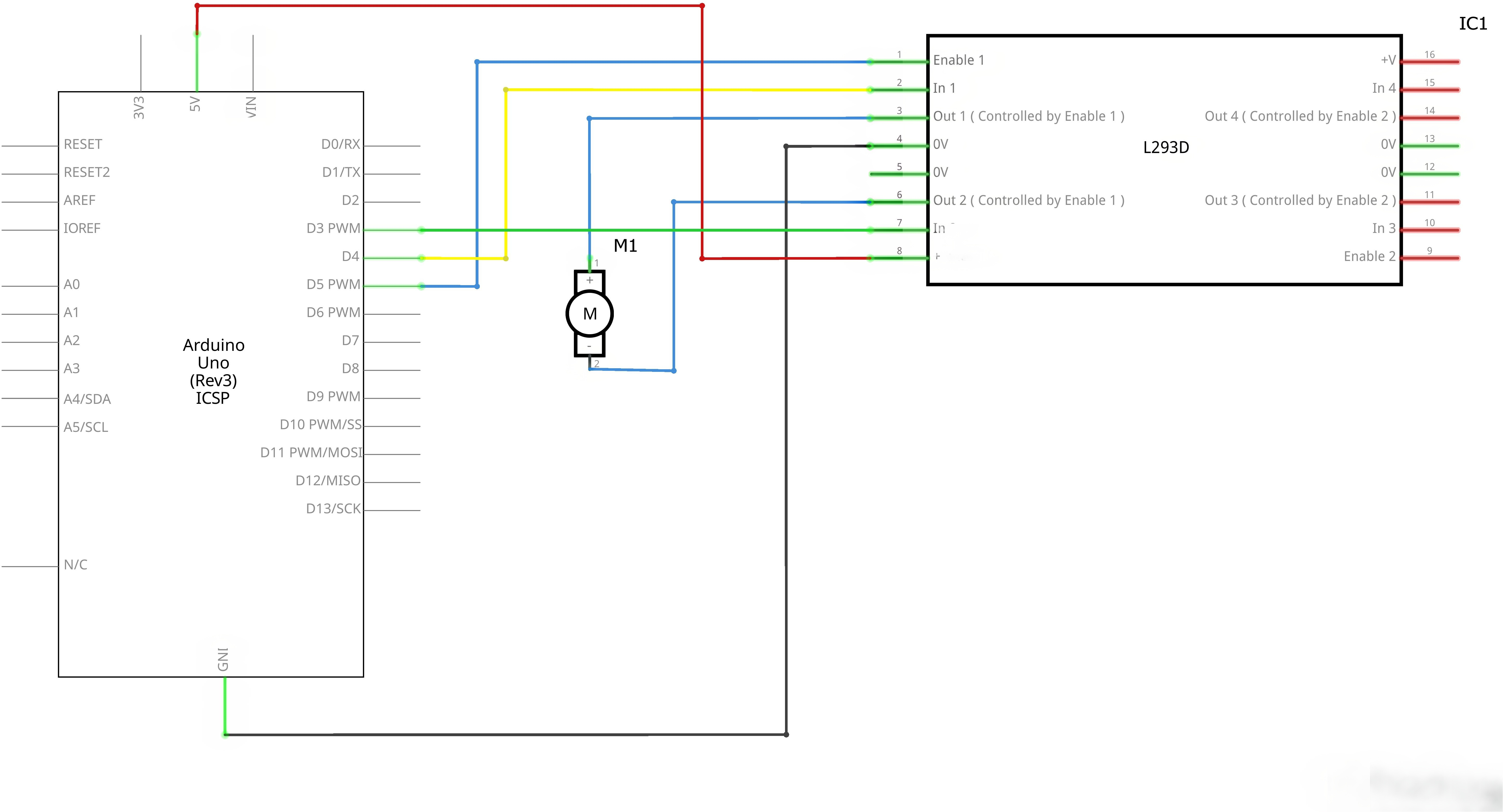
¶ Connection Schematic
¶ Wiring diagram
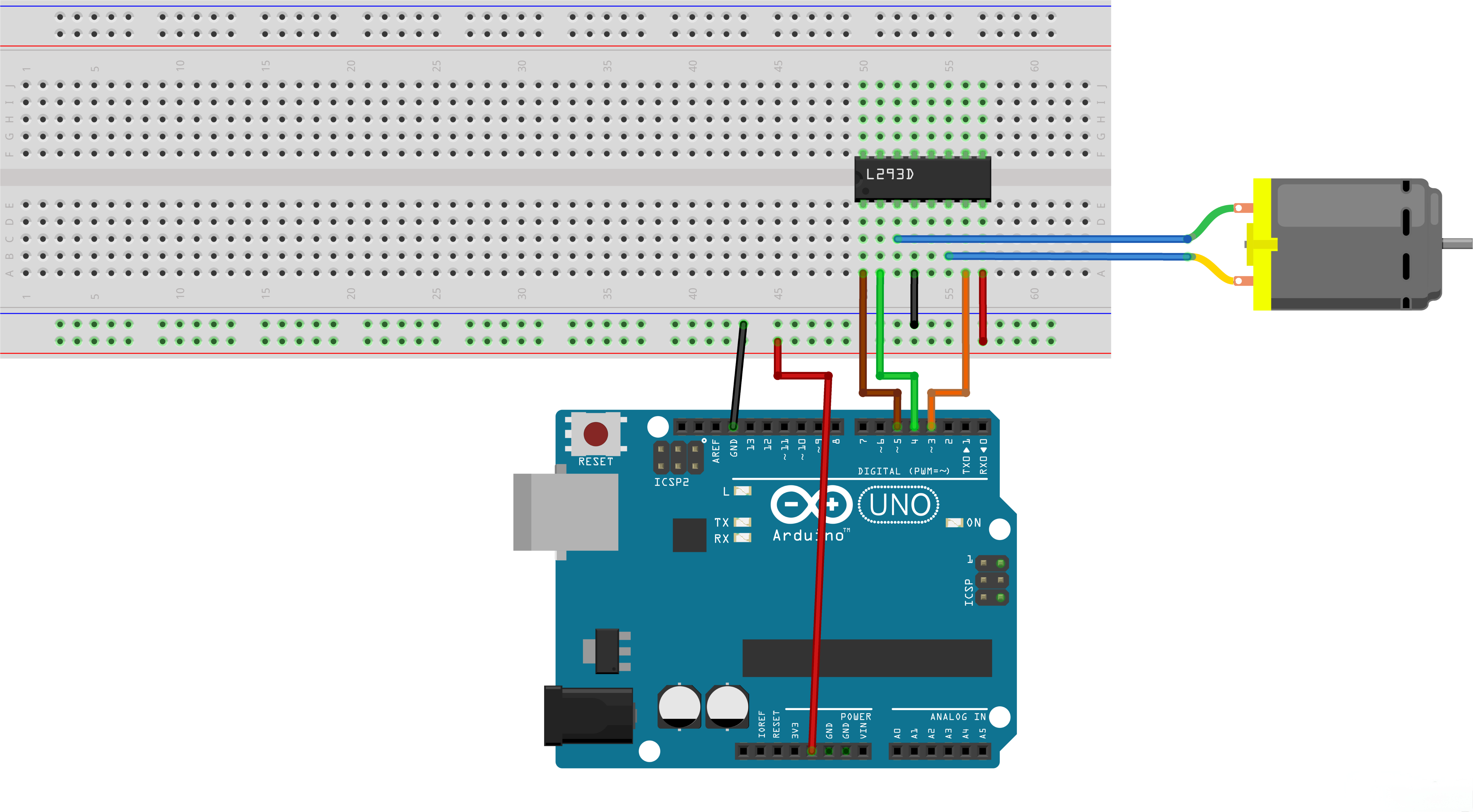
Pin Configuration (UNO to L293D):
| UNO Pin | L293D Pin | Function |
|---|---|---|
| GPIO 5 | Enable | Motor enable/speed |
| GPIO 4 | In1 | Direction control |
| GPIO 3 | In2 | Direction control |
| 5V | VCC | Power supply |
| GND | GND | Ground |
¶ Code
You can click the blue text link to download the program file to your local device, and double-click the file to open it after the download is complete. Please note: Before opening the file, ensure that you have installed the Arduino IDE development environment and completed the installation of relevant components such as the board support package and driver corresponding to the UNO 2 development board. If you have any questions about this operation process, you can refer to the "part 1" chapter of the document for detailed guidance.
With this code, the UNO board will control a DC motor using an L293D motor driver chip, demonstrating three different motor control techniques: back-and-forth rotation, fast/slow stopping, and PWM speed control. The code also provides serial monitor feedback for each operation.
Click the Serial Monitor button to turn on the serial monitor. The basics about the serial monitor are introduced in details in tutorial 4 in part 2.
#define ENABLE 5 / enable connect to D5
#define DIRA 3 / In1 connect to D3
#define DIRB 4 /In2 connect to D4int i;
Hardware Configuration and Variable Definition:
#define ENABLE 5: Defines the enable pin (D5) connected to L293D's enable pin#define DIRA 3: Defines direction pin A (D3) connected to L293D's In1 pin#define DIRB 4: Defines direction pin B (D4) connected to L293D's In2 pinint i: Declares an integer variable used as a loop counter
void setup() {
//---set pin direction
pinMode(ENABLE,OUTPUT);
pinMode(DIRA,OUTPUT);
pinMode(DIRB,OUTPUT);
Serial.begin(9600);
}
setup() Function:Initializes the system and configures the GPIO pins.
- Pin Direction Setup: Configures all motor control pins as outputs
pinMode(ENABLE, OUTPUT): Enable pin for motor controlpinMode(DIRA, OUTPUT): Direction control pin ApinMode(DIRB, OUTPUT): Direction control pin BSerial.begin(9600): Initializes serial communication at 9600 baud rate for operation feedback
loop() Function Overview:The main loop that demonstrates three different motor control techniques in sequence.
1. Back-and-Forth Rotation Module:
//---back and forth example
Serial.println("One way, then reverse");
digitalWrite(ENABLE,HIGH); // enable on
for (i=0;i<5;i++) {
digitalWrite(DIRA,HIGH); //one way
digitalWrite(DIRB,LOW);
delay(500);
digitalWrite(DIRA,LOW); //reverse
digitalWrite(DIRB,HIGH);
delay(500);
}
digitalWrite(ENABLE,LOW); // disable
delay(2000);
- Operation Description: Makes the motor rotate in one direction and then reverse
- Enable Control:
digitalWrite(ENABLE, HIGH)turns the motor on - Direction Control:
- Forward:
DIRA = HIGH,DIRB = LOW - Reverse:
DIRA = LOW,DIRB = HIGH
- Forward:
- Loop Control: Uses a for loop to repeat the forward/reverse cycle 5 times
- Delay: 500ms in each direction, then 2000ms pause before next section
2. Fast/Slow Stop Module:
Serial.println("fast Slow example");
//---fast/slow stop example
digitalWrite(ENABLE,HIGH); //enable on
digitalWrite(DIRA,HIGH); //one way
digitalWrite(DIRB,LOW);
delay(3000);
digitalWrite(ENABLE,LOW); //slow stop
delay(1000);
digitalWrite(ENABLE,HIGH); //enable on
digitalWrite(DIRA,LOW); //one way
digitalWrite(DIRB,HIGH);
delay(3000);
digitalWrite(DIRA,LOW); //fast stop
delay(2000);
- Operation Description: Demonstrates two different ways to stop the motor
- Slow Stop:
digitalWrite(ENABLE, LOW)gradually stops the motor by removing power - Fast Stop:
digitalWrite(DIRA, LOW)(along withDIRBalready LOW) provides a braking effect by shorting the motor terminals - Duration: Each direction runs for 3000ms before stopping
3. PWM Speed Control Module:
Serial.println("PWM full then slow");
//---PWM example, full speed then slow
analogWrite(ENABLE,255); //enable on
digitalWrite(DIRA,HIGH); //one way
digitalWrite(DIRB,LOW);
delay(2000);
analogWrite(ENABLE,180); //half speed
delay(2000);
analogWrite(ENABLE,128); //half speed
delay(2000);
analogWrite(ENABLE,50); //half speed
delay(2000);
analogWrite(ENABLE,128); //half speed
delay(2000);
analogWrite(ENABLE,180); //half speed
delay(2000);
analogWrite(ENABLE,255); //half speed
delay(2000);
digitalWrite(ENABLE,LOW); //all done
delay(10000);
- Operation Description: Demonstrates motor speed control using PWM (Pulse Width Modulation)
- PWM Values:
255: Full speed (100% duty cycle)180: High speed (~70% duty cycle)128: Medium speed (~50% duty cycle)50: Low speed (~20% duty cycle)
- Speed Transition: Gradually decreases speed, then increases back to full speed
- Duration: Each speed level lasts for 2000ms
- Final Delay: 10000ms pause before the loop repeats
<