¶ First look UNO
¶ 1.What is Arduino?
Based on the idea of implementing easy-to-use hardware and software, Arduino is an open-source electronics platform.
¶ Input Signals
Arduino boards are able to read input signals:
- Acceleration and steering
- A finger on a button
- A Twitter message
- Light on a sensor
¶ Output Signals
and turn it into an output signals:
- Activating a motor
- Turning on an LED
- Publishing something online
You can tell your board what to do by sending a set of instructions to the microcontroller on the board. To do so you use the Arduino programming language (based on Wiring), and the Arduino Software (IDE, integrated development environment), based on Processing.
A worldwide community of makers - students, hobbyists, artists, programmers, and professionals - has gathered around this open-source platform. Their contributions have added up to an incredible amount of accessible knowledge that can be of great help to novices and experts alike.
Do you want to build a robot that can run, dance, and be controlled by you?
Do you want to make a smart bracelet that can not only detect your heart rate and step number but also display time, date, and play songs?
Do you want to control deliveries at home, even when you are at work?
Do you want to make a device that can automatically pour coffee for you?
Do you want to create all kinds of cool and romantic lighting effects?
Do you want an Infinity Gauntlet like the one in the Avengers?
As long as you want it, Arduino can help you achieve it.
¶ 2.The History of Arduino
As an open-source project founded by Massimo Banzi, David Cuartielles, Tom Igoe, Gianluca Martino, and David Mellis, Arduino has been the brain of thousands of projects, from everyday objects to complex scientific instruments.
When it comes to its history, Arduino was initially developed at the Interaction Design Institute Ivrea, in northern Italy.
It derives from Wiring, a platform built by Hernando Barragán as his master's thesis at Interaction-Ivrea. Hernando was advised by Massimo and Casey Reas. Wiring and, in turn, Arduino build on previous work by both Banzi and Reas -- Banzi's Programma2003 electronics prototyping platform and the Processing platform by Reas and Ben Fry. Early versions of both Wiring and Arduino also relied upon Pascal Stang’s avrlib libraries.
The initial Arduino boards were designed by Massimo Banzi and David Cuartielles. David Mellis developed the initial Arduino software based on Wiring, with many contributions early on by Nicholas Zambetti. Tom Igoe at ITP in New York was an early adopter and advisor on the Arduino project. Gianluca Martino helped with manufacturing and hardware design. The Arduino project is now supported by an international company with offices and people around the world.
Arduino takes its name from a bar in Ivrea, which was named after an early king of Italy from Ivrea.
¶ 3.Introduction of Board
We will use the ELEGOO UNO as an example to illustrate the main circuit components of an Arduino circuit board.
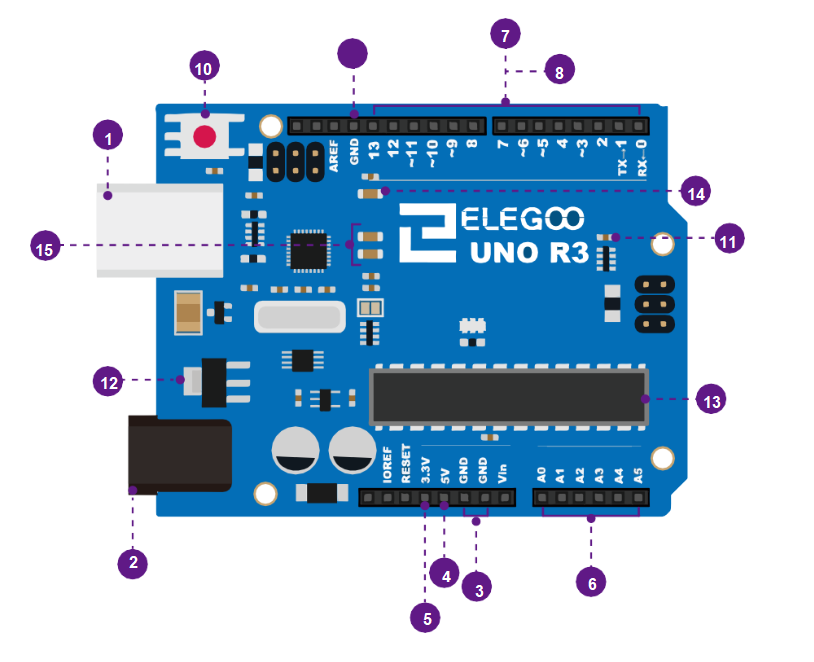
- USB connection
- 6V~12V barrel jack
- GND
- 5V pin supplies
- 3.3V pin supplies
- analog pin
- digital pin
- (pwm~)
- GND
- Reset Button
- Power LED Indicator
- Voltage Regulator
- MainIC
- Pin D13 indicator LED
- Serial communicationindicator LEDs
¶ Volts (USB / Barrel Jack)
Every Arduino board needs a way to be connected to a power source. The ELEGOO UNO can be powered from a USB cable coming from your computer or a wall power supply (like this) that is terminated in a barrel jack. In the picture above the USB connection is labeled (1) and the barrel jack is labeled (2).
The USB connection is also how you will load code onto your Arduino board. More on how to program with Arduino can be found in our Installing and Programming Arduino tutorial.
NOTE: Do not use a power supply that provides more than 20 volts beacause you will overpower (and thereby destroy) your Arduino. The recommended voltage for most Arduino models is between 6 and 12 volts.
Pins (5V, 3.3V, GND, Analog, Digital, PWM, AREF)
The pins on your Arduino are your way to connect wires to construct a circuit ( typically in conjuction with a breadboard and some wire). They usually have black plastic ‘headers’ that allow you to plug a wire right into the board. The Arduino has several different kinds of pins, each of which is labeled on the board and used for different functions.
GND (3): Short for ‘Ground’. There are several GND pins on the Arduino, any of which can be used to ground your circuit.
5V (4) & 3.3V (5): As you might guess, the 5V pin supplies 5 volts of power, and the 3.3V pin supplies 3.3 volts of power. Most of the simple components used with the Arduino run happily off of 5 or 3.3 volts.
Analog (6): The area of pins under the ‘Analog In’ label (A0 through A5 on the UNO) are Analog In pins. These pins can read the signal from an analog sensor (like a temperature sensor) and convert it into a digital value that we can read.
Digital (7): Across from the analog pins are the digital pins (0 through 13 on the UNO). These pins can be used for both digital input (like telling if a button is pushed) and digital output (like powering an LED).
PWM (8):You may have noticed the tilde (~) next to some of the digital pins (3, 5, 6, 9, 10, and 11 on the UNO). These pins act as normal digital pins, but can also be used for something called Pulse-Width Modulation (PWM). We have a tutorial on PWM, but for now, think of these pins as being able to simulate analog output (like fading an LED in and out).
AREF (9): Stands for Analog Reference. Most of the time you can leave this pin alone. It is sometimes used to set an external reference voltage (between 0 and 5 Volts) as the upper limit for the analog input pins.
If you are confused about the code in the following course, you can hold down Ctrl and click on the following website to refer to the grammar.** https://www.arduino.cc/reference/en/#functions**