¶ Four Digit Seven Segment Display
¶ Overview
In this tutorial, you will learn how to use a 4-digit 7-segment display.
When using 1-digit 7-segment display, please notice that if it is common anode, the common anode pin connects to the power source; if it is common cathode, the common cathode pin connects to the GND.
When using 4-digit 7-segment display, the common anode or common cathode pin is used to control which digit is displayed. Even though there is only one digit working, the principle of Persistence of Vision enables you to see all numbers displayed because each the scanning speed is so fast that you can hardly notice the intervals.
¶ Component Required:
(1) x 830 tie-points breadboard
(1)x 74HC595 IC
(1) x 4 Digit 7-Segment Display
(4) x 220 ohm resistors
(23) x M-M wires (Male to Male jumper wires)
¶ Component Introduction
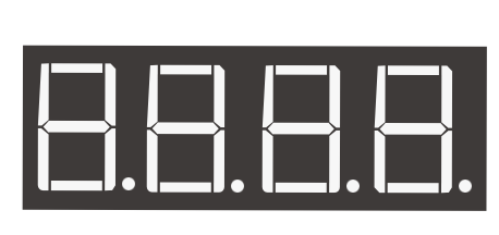
Four Digital Seven Segment Display
- Product Overview
The 5643 series (including model CPS05643AB) is a compact four-digit, seven-segment display module designed for embedded systems. It integrates four independent digits for dynamic display of numbers and symbols.The series is available in both common cathode (5643A) and common anode (5643B) versions, to accommodate different driving logic requirements. - Package & Dimension Specifications
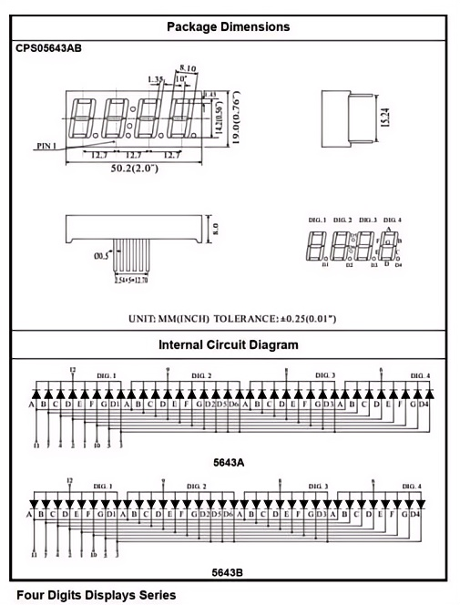
This module features a compact through-hole package with the following key dimensions:
Total Length: 50.2 mm (2.0 inches), with each digit segment measuring 12.7 mm wide
Overall Height: 19.0 mm (0.75 inches)
Pin Pitch: 1.27 mm (0.05 inches), compatible with standard header footprints
Tolerance: All dimensions are subject to ±0.25 mm (0.01 inches) tolerance
The module uses a standard dual in-line pin layout, making it easy to solder and integrate into PCB designs. - Internal Circuit Structure
The internal circuit architecture enables flexible driving:
5643A (Common Cathode): The common terminal of each digit is the cathode, requiring a low-level signal to activate the corresponding segments.
5643B (Common Anode): The common terminal of each digit is the anode, requiring a high-level signal to activate the corresponding segments.
Segment Pins: Identical segments (A-G, DP) across all digits are internally connected in parallel, supporting multi-digit dynamic scanning.
Common Pins: Each digit has an independent common pin, used for digit selection control.
¶ Wiring Comparison between 74HC595 and Digital Tube
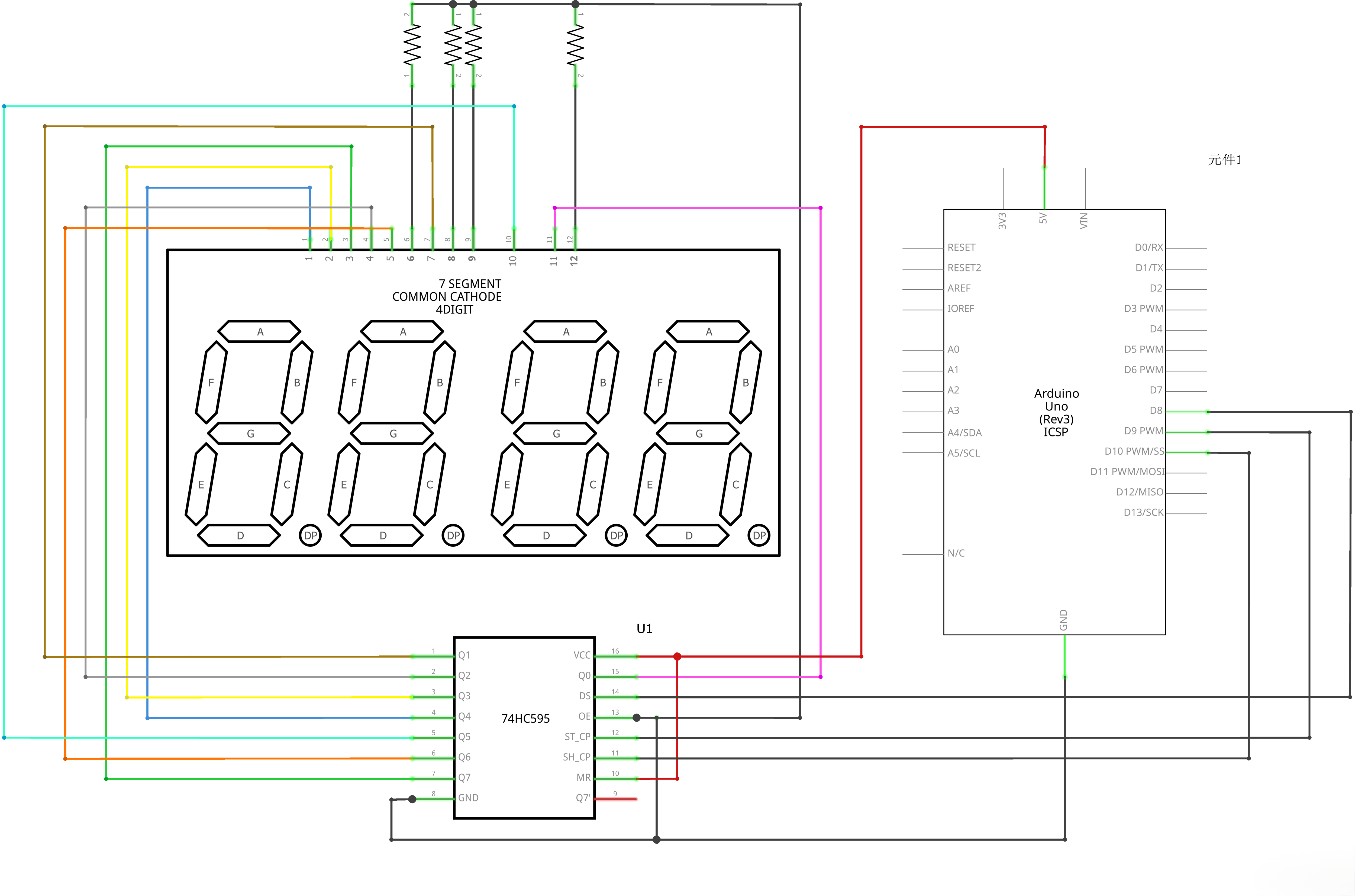
¶ Connection Schematic
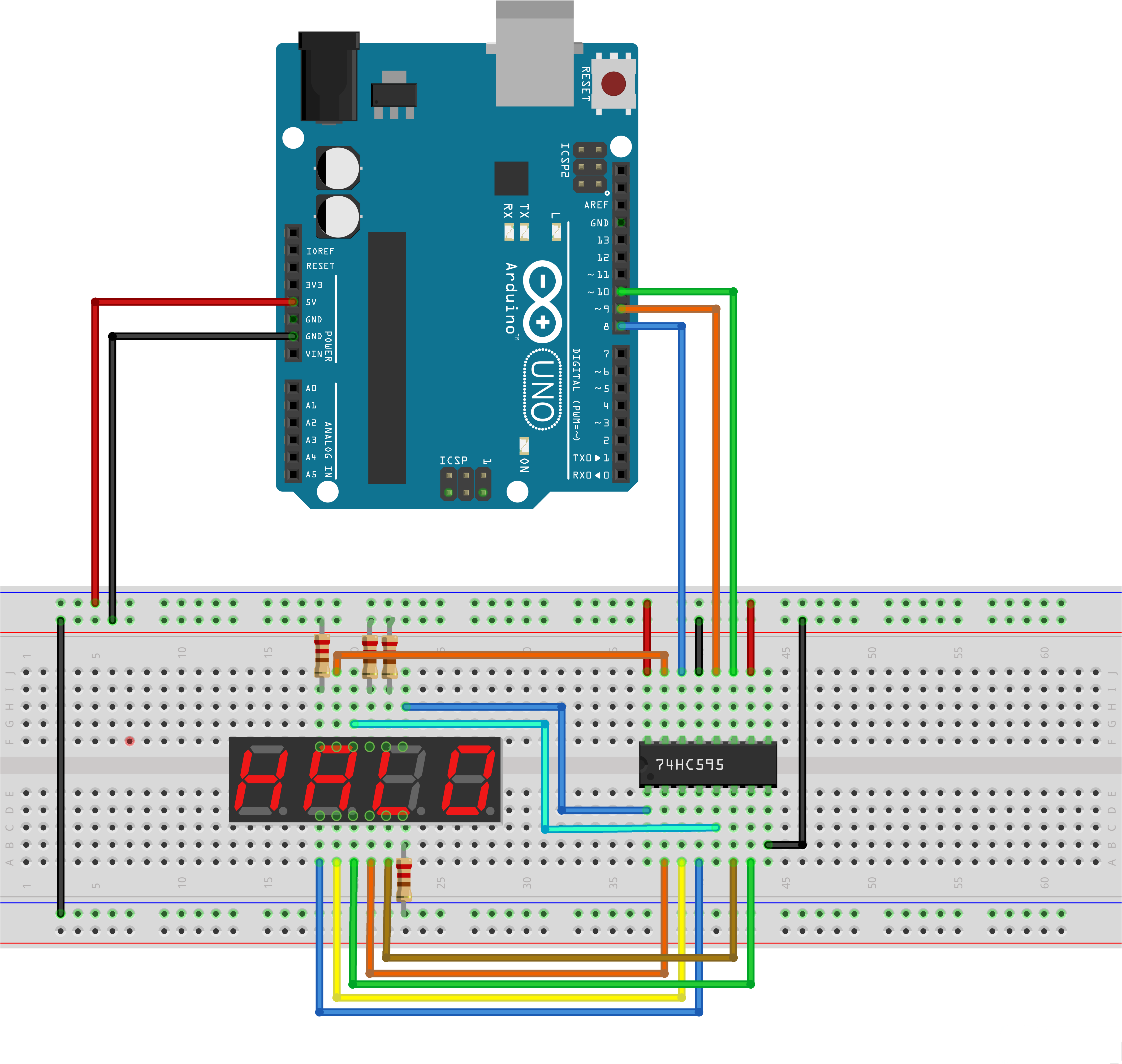
¶ Wiring diagram
¶ Code
You can click the blue text link to download the program file to your local device, and double-click the file to open it after the download is complete. Please note: Before opening the file, ensure that you have installed the Arduino IDE development environment and completed the installation of relevant components such as the board support package and driver corresponding to the UNO R3. If you have any questions about this operation process, you can refer to the "part 1" chapter of the document for detailed guidance.
Click the Serial Monitor button to turn on the serial monitor. The basics about the serial monitor are introduced in details in tutorial 4 in part 2.
int latch=9; //74HC595 pin 9 STCP
int clock=10; //74HC595 pin 10 SHCP
int data=8; //74HC595 pin 8 DSunsigned char table[]=
{0x3f,0x06,0x5b,0x4f,0x66,0x6d,0x7d,0x07,0x7f,0x6f,0x77,0x7c
,0x39,0x5e,0x79,0x71,0x00};//Display digital data
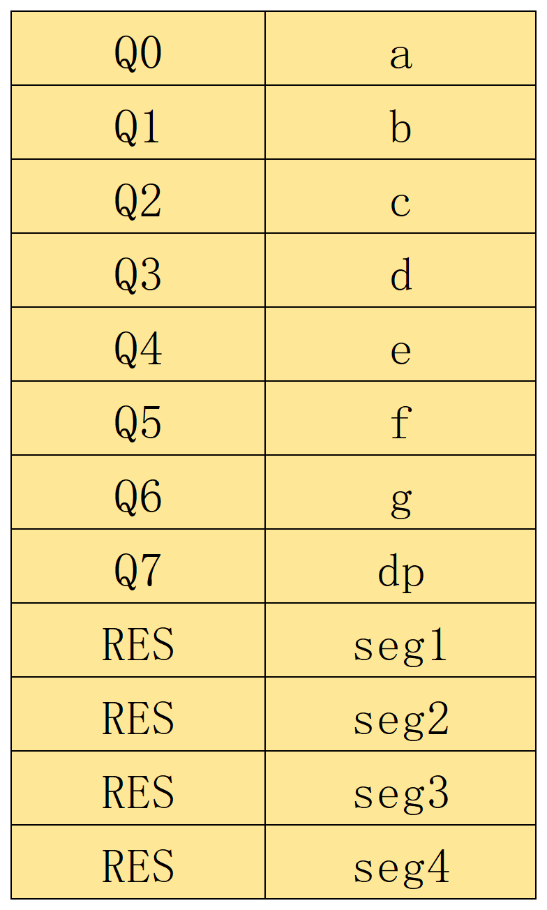
Pin Definitions and Display Table:
int latch=9;:Arduino digital pin 9 connected to STCP of 74HC595 (latch pin)int clock=10;:Arduino digital pin 10 connected to SHCP of 74HC595 (clock pin)int data=8;:Arduino digital pin 8 connected to DS of 74HC595 (data pin)unsigned char table[]:Array of hex values representing 7-segment display patterns for digits 0-15 and blank- 0x3f: 0, 0x06: 1, 0x5b: 2, 0x4f: 3, 0x66: 4
- 0x6d: 5, 0x7d: 6, 0x07: 7, 0x7f: 8, 0x6f: 9
- 0x77: A, 0x7c: B, 0x39: C, 0x5e: D, 0x79: E, 0x71: F
- 0x00: Blank
void setup() {
pinMode(latch,OUTPUT);
pinMode(clock,OUTPUT);
pinMode(data,OUTPUT);
}
Setup Function:
pinMode(latch,OUTPUT);:Sets the latch pin as outputpinMode(clock,OUTPUT);:Sets the clock pin as outputpinMode(data,OUTPUT);:Sets the data pin as output
/* The most common method of using 74CH595
- latch->LOW : Begin transmitting signals.
- shiftOut(dataPin, clockPin, bitOrder, value)
- dataPin: the pin on which to output each bit. Allowed data types: int.
- clockPin: the pin to toggle once the dataPin has been set to the correct value. Allowed data types: int.
- bitOrder: which order to shift out the bits; either MSBFIRST or LSBFIRST. (Most Significant Bit First, or, Least Significant Bit First).
- value: the data to shift out. Allowed data types: byte.
- latch->HIch : The end of the transmission signal.
*/
void Display(unsigned char num)
{digitalWrite(latch,LOW);
shiftOut(data,clock,MSBFIRST,table[num]);
digitalWrite(latch,HIGH);}
Display() Function:
void Display(unsigned char num):Function to display a number on the 7-segment displaydigitalWrite(latch,LOW);:Sets latch pin low to prepare for data transfershiftOut(data,clock,MSBFIRST,table[num]);:Shifts out the display patterndata:Pin to send data throughclock:Pin to clock the dataMSBFIRST:Send most significant bit firsttable[num]:Display pattern for the specified number
digitalWrite(latch,HIGH);:Sets latch pin high to update the display
void loop() {
Display(1);
delay(500);
Display(2);
delay(500);
Display(3);
.........
}
Loop Function:
- Cycles through numbers 1 to 15, displaying each on the 7-segment display
Display(n);:Displays the number ndelay(500);:Delays 500 milliseconds between each number- Displays the following sequence: 1, 2, 3, 4, 5, 6, 7, 8, 9, 10(A), 11(B), 12(C), 13(D), 14(E), 15(F)
¶ Troubleshooting
- Display Not Working:Check connections between Arduino, 74HC595, and 7-segment display
- Incorrect Characters:Verify the 7-segment pin mapping and display table values
- Shift Register Issues:Check that the 74HC595 is receiving proper clock and data signals
- Wiring:Double-check the connections according to the pin definitions
- Display Brightness:Ensure proper current limiting resistors are used with the 7-segment display
¶ Advanced Lesson: Controlling Each 7-Segment Digit Independently
Now that you have completed the basic examples, you may want to control each digit individually and show different numbers on each display.
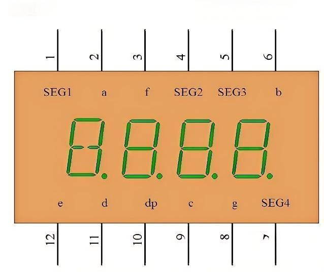
From the pinout diagram of the 4-digit 7-segment display, you can see that seg1–seg4 control whether each digit is turned ON or OFF.Since we are using a common-cathode 4-digit 7-segment display, all four digits will light up if seg1–seg4 are connected directly to GND.
To control one digit at a time, you must connect these seg pins to digital output pins on the Arduino UNO, so the Arduino can turn each digit ON or OFF.
example:
int seg1= 4;
int seg2= 11;
int seg3= 12;
int seg4= 13;
Assign the seg pins to UNO pins, and set them as outputs in setup():
pinMode(seg1,OUTPUT);
pinMode(seg2,OUTPUT);
pinMode(seg3,OUTPUT);
pinMode(seg4,OUTPUT);
At this point, you can already turn each digit ON or OFF independently.
¶ Controlling What Each Digit Displays
Next, we will make each digit show a different number. The idea is simple:Turn ON only one digit, display a number on it, and keep all other digits OFF.
Based on the code you already have, add this function:
void lightOneDigit(int digitIndex, int num) {
// Step 1: Turn OFF all digits to prevent ghosting
digitalWrite(seg1, HIGH);
digitalWrite(seg2, HIGH);
digitalWrite(seg3, HIGH);
digitalWrite(seg4, HIGH);// Step 2: Send the segment code for the number you want to display
Display(num);// Step 3: Turn ON only the selected digit
digitalWrite(digitIndex, LOW);
}
¶ How to Use It
To display a number on a specific digit, just call:
lightOneDigit(seg1, 0);
This means:
- seg1 → the digit you want to light up
- 0 → the number to display
In the same way:
- lightOneDigit(seg2, 1); → seg2 shows the number 1
- lightOneDigit(seg3, 2); → seg3 shows the number 2
- lightOneDigit(seg4, 3); → seg4 shows the number 3
By calling these functions quickly one after another in loop(), you can make all four digits show different numbers at the same time.