¶ Rotary Encode Module
¶ Overview
In this experiment, we will learn how to use the rotary encode module.
Rotary encoder useful for making an electronic pot etc. Connection identsare printed on the PCB
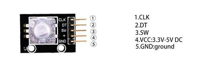
¶ Component Introduction
RotaryEncoders:
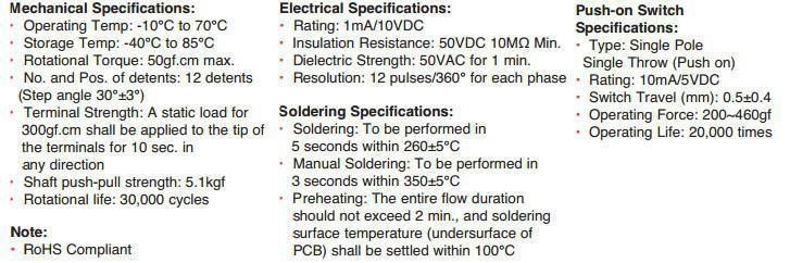
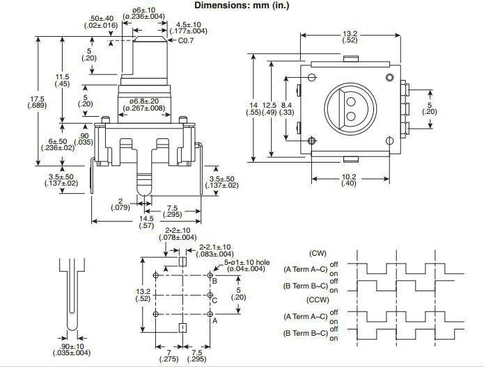
Principle
Incrementalencoder
Incremental encoders give two-phase square wave, the phase difference between them 90 °, often referred to as A and B channels. One of the channels is given and speed-related Information, at the same time, by sequentially comparing two channel signals, the direction of rotation of the information obtained. There is also a special signal called Z or Zero channel, which gives the absolute zero position encoder, the signal is a square wave with the center line of channel A square wave coincide.
Clockwisecounterclockwise
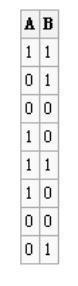
Incremental encoder accuracy depends on the mechanical and electrical two factors, these factors are: Raster indexing error, disc eccentricity, bearing eccentricity, e-reading Several means into the optical portion of the errors and inaccuracies. Determine the encoder resolution is measured in electrical degrees, the encoder accuracy depends Set the pulse encoder generates indexing. The following electrical degrees with a 360 ° rotation of the shaft to said machine, and rotation of the shaft must be a full week of Period. To know how much electrical equivalent of the mechanical angle of 360 degrees can be calculated with the following formula: Electrical 360 = Machine 360 ° / n ° pulses /revolution
Encoder indexing error is the electrical angle of the unit two successive pulse maximum offset to represent. Error exists in any encoder, which Is caused by the aforementioned factors. Eltra encoder maximum error is ± 25 electrical degrees (declared in any condition), equivalent to the rated Offset values ± 7%, as the phase difference 90 ° (electrical) of the two channels of the maximum deviation± 35 electrical degreesis equal to ± 10% deviation left Ratings Right.
¶ Connection Schematic
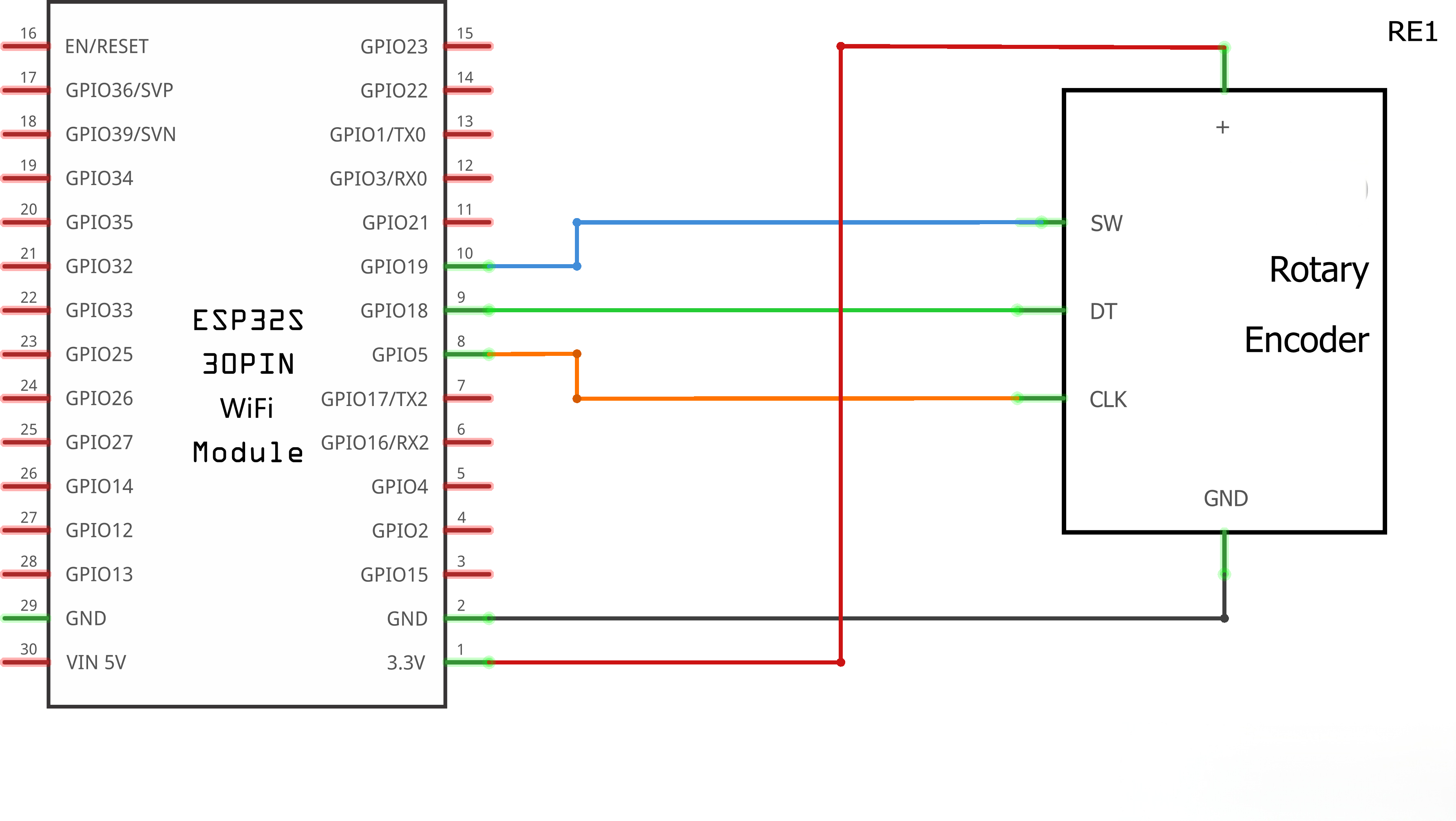
¶ Wiringdiagram
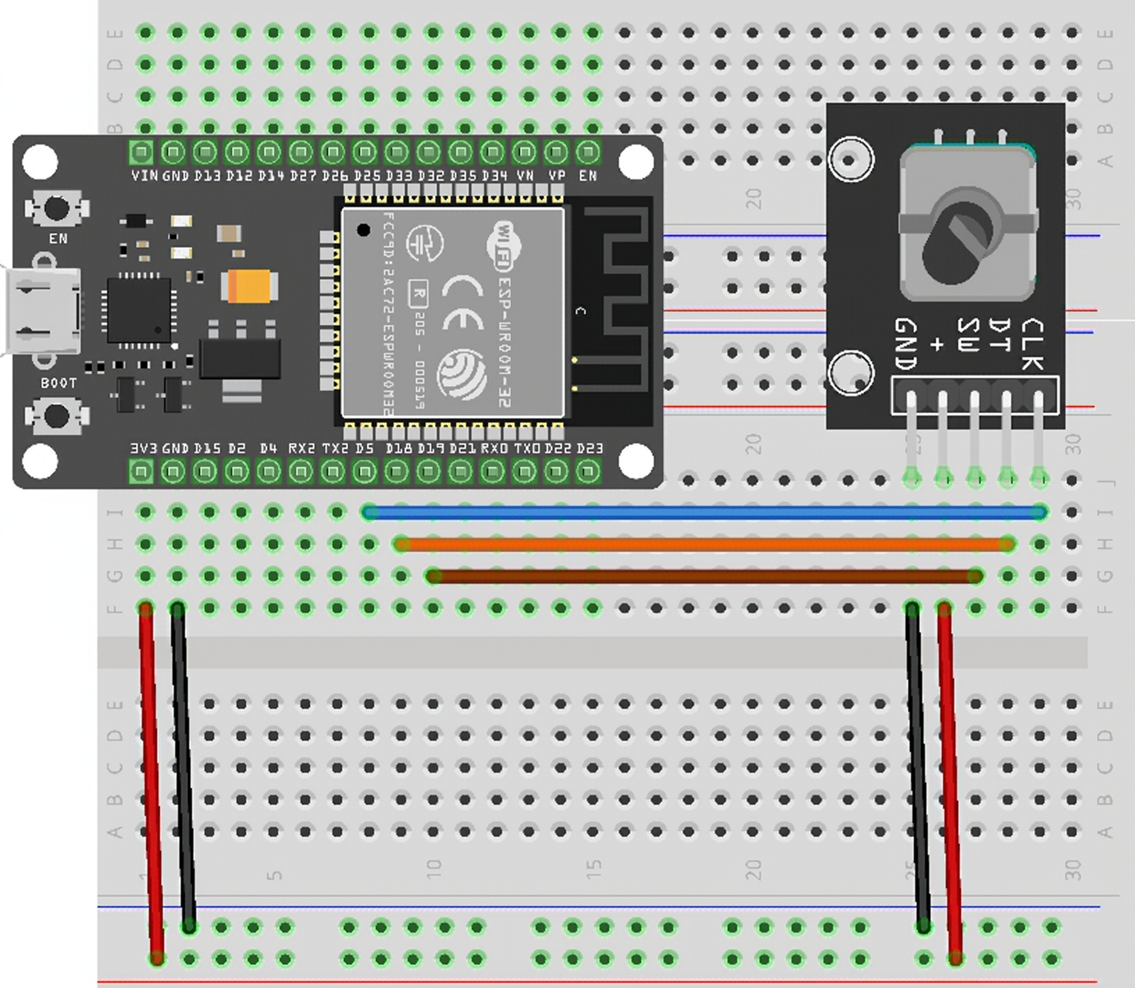
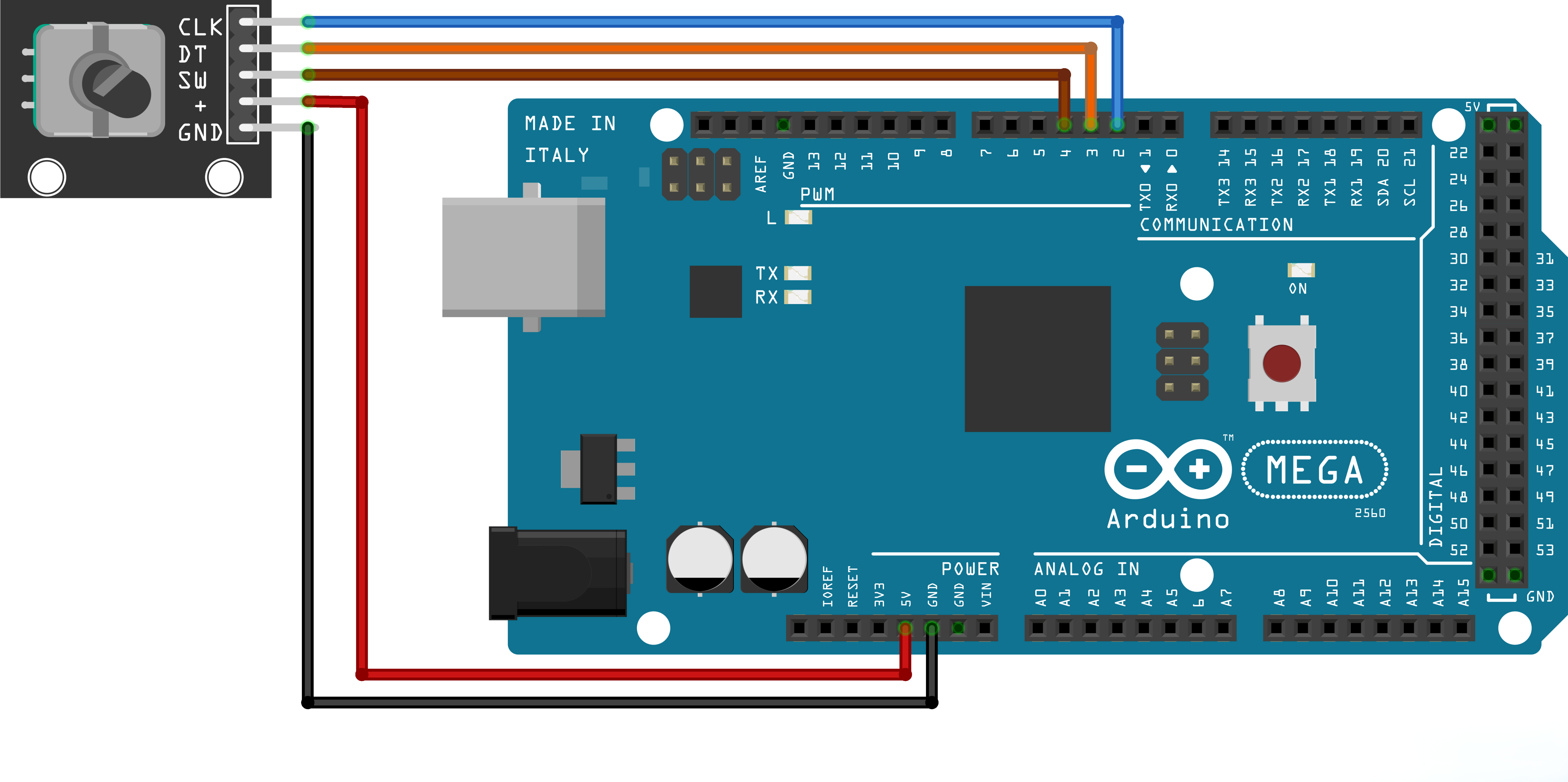
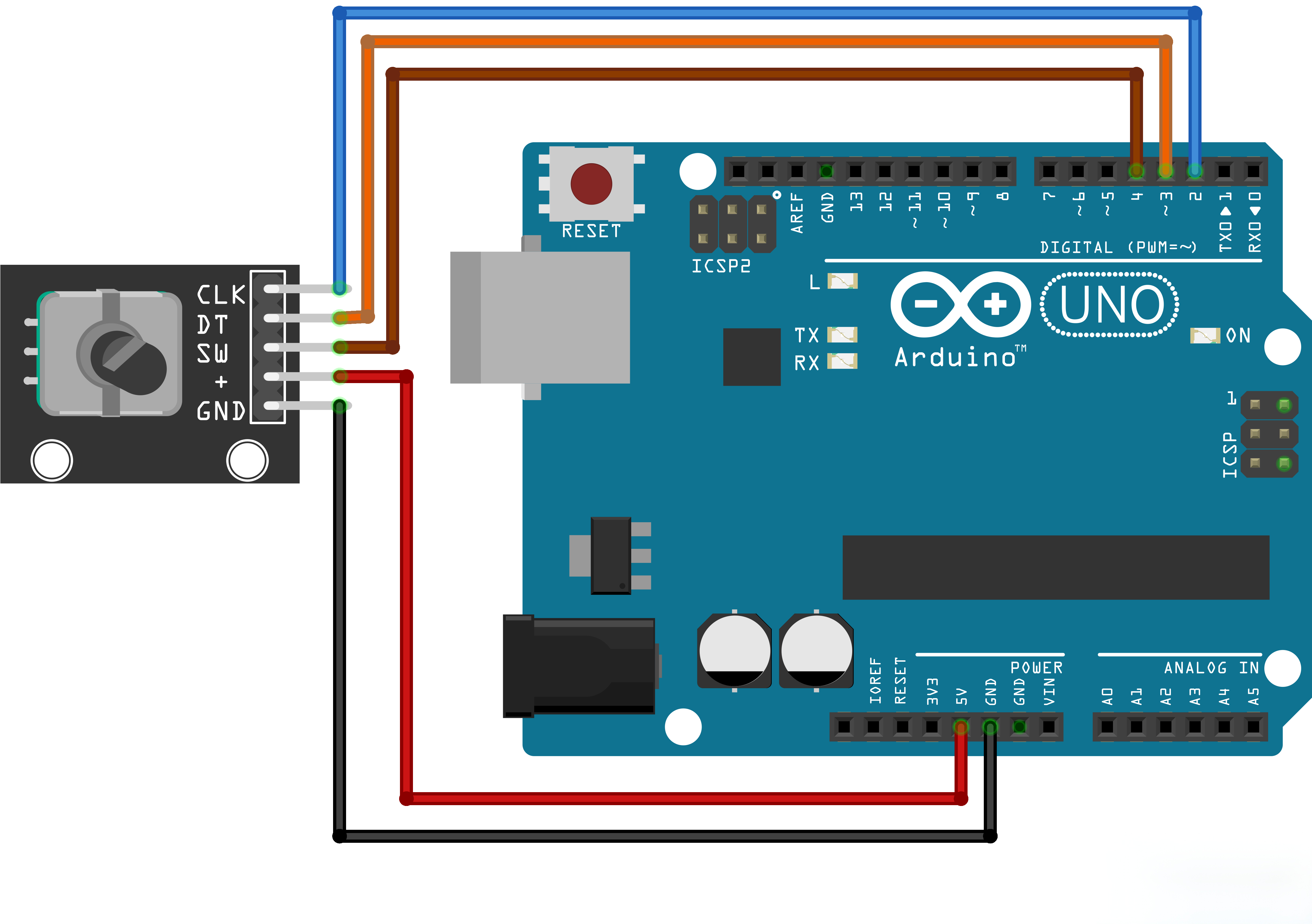
¶ Code
You can click the blue text link to download the program file to your local device, and double-click the file to open it after the download is complete. Please note: Before opening the file, ensure that you have installed the Arduino IDE development environment and completed the installation of relevant components such as the board support package and driver corresponding to the board.
#define CLK 5
#define DT 18
#define SW 19int count = 0;
uint8_t lastState = 0;
unsigned long lastPollTime = 0;
const unsigned long POLL_INTERVAL = 1;
- count: Records the number of rotation turns. A positive value indicates clockwise rotation, while a negative value indicates counterclockwise rotation.
- lastState: Stores the previous state sampled from the encoder.
- lastPollTime: Records the timestamp of the last encoder status detection.
- POLL_INTERVAL: Defines the polling interval for encoder status detection, which is set to 1 millisecond.
lastState = (digitalRead(CLK) << 1) | digitalRead(DT);
within the setup function
- digitalRead(CLK): Reads the logic level of the CLK pin, where 0 stands for low level and 1 stands for high level.
- << 1: Shifts the value obtained from the CLK pin left by one bit.
- | digitalRead(DT): Combines the status of the CLK pin and the DT pin via a bitwise OR operation.
- Result: A single integer ranging from 0 to 3 is used to represent all combined logic states of the two pins.
The loop function consists of multiple components, which will be explained one by one in the following content.
unsigned long now = millis();
if (now - lastPollTime >= POLL_INTERVAL)
{
lastPollTime = now;
pollEncoder();
}
- millis(): Returns the number of milliseconds elapsed since the ESP32 was powered on and started.
- The encoder status is polled every 1 millisecond to prevent missing any rotation signals.
static bool lastSwState = HIGH;
bool swState = digitalRead(SW);
if (swState == LOW && lastSwState == HIGH)
{
delay(50);
if (digitalRead(SW) == LOW && count != 0)
{
count = 0;
Serial.print("count:");
Serial.println(count);
}
while (digitalRead(SW) == LOW);
}
lastSwState = swState;
This part of the code implements the key reset function. The execution flow is: detect key press → confirm via debouncing → clear the rotation count value → wait for key release. Note that delay(50) is adopted for software key debouncing in this program.
pollEncoder()
void pollEncoder()
{
// Read current states of CLK and DT pins
uint8_t currA = digitalRead(CLK);
uint8_t currB = digitalRead(DT);// Combine into 2-bit state: bit1=CLK, bit0=DT
uint8_t currState = (currA << 1) | currB;// Skip if state hasn't changed since last poll
if (currState == lastState)
return;// Transition code (not used in this simplified detection logic)
// uint8_t transition = (lastState << 2) | currState;// Detect clockwise rotation (complete cycle ending at 00)
// CW sequence: 00 → 01 → 11 → 10 → 00
// Count only when returning to 00 from 10 (last step of CW cycle)
if (lastState == 0b10 && currState == 0b00)
{
count++;
Serial.print("count:");
Serial.println(count);
}
// Detect counter-clockwise rotation (complete cycle ending at 00)
// CCW sequence: 00 → 10 → 11 → 01 → 00
// Count only when returning to 00 from 01 (last step of CCW cycle)
else if (lastState == 0b01 && currState == 0b00)
{
count--;
Serial.print("count:");
Serial.println(count);
}// Update lastState for next poll cycle
lastState = currState;
}
- uint8_t currA = digitalRead(CLK);: Reads the current logic level of Phase A (clock pin).
- uint8_t currB = digitalRead(DT);: Reads the current logic level of Phase B (data pin).
- uint8_t currState = (currA << 1) | currB;: Combines the two pin levels into a 2-bit status code including four combinations: 00, 01, 10, 11.
- if (currState == lastState) return;: Exits the current loop directly if the pin state keeps unchanged without subsequent operations.
- uint8_t transition = (lastState << 2) | currState;: Merges the previous state and the current state to judge the rotation direction of the rotary encoder.
- if (lastState == 0b10 && currState == 0b00): Confirms clockwise rotation when the encoder state changes from 10 to 00.
- count++;: Increases the rotation count value by 1.
- else if (lastState == 0b01 && currState == 0b00): Confirms counterclockwise rotation when the encoder state changes from 01 to 00.
- count--;: Decreases the rotation count value by 1.
- lastState = currState;: Updates the stored historical state to the latest pin state for next cycle comparison.