¶ Header
¶ Overview
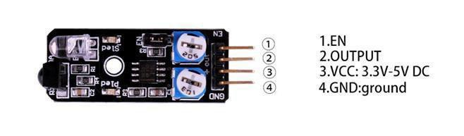
Non logic chip oscillation frequency regulation 38KHz detection circuit. This infrared 38KHZ obstacle avoidance module can completely block the traditional photoelectric obstacle detection distance and a single normally open or normally closed signal output function.
¶ Obstacle avoidance sensor module
IR-reflection sensor, useful for obstacle avoidance applications. When an obstacle is in front of the IR sender/receiver the ‘Out’ pin is switched low (active low). The circuit sensitivity can be adjusted with a pot. The obstacle detection distance can be adjusted up to approximately 7cm. An enable (EN) jumper can be fitted for continuous operation. Removal of the EN jumper allows an external logic signal (at the EN pin) to switch the detector on and off (low = active, high = off).
¶ Component Introduction
Obstacle avoidancemodule:
The basic concept of IR(infrared) obstacle detection is to transmit the IR signal(radiation) in a direction and a signal is received at the IR receiver when the IR radiation bounces back from a surface of theobject.
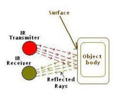
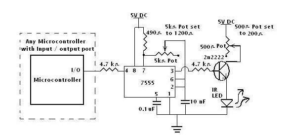
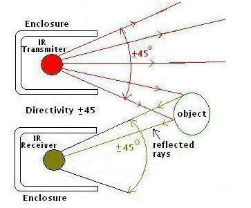
Infrared obstacle avoidance sensor is designed for the design of a wheeled robot obstacle avoidance sensor distance adjustable.
This ambient light sensor Adaptable, high precision, having a pair of infrared transmitter and receiver, transmitter tubes emit a certain frequency of infrared, When detecting the direction of an obstacle (reflector), the infrared receiver tube receiver is reflected back, when the indicator is lit, Through the circuit, the signal output interface output digital signal that can be detected by means of potentiometer knob to adjust the distance, the effective distance From 2 ~ 40cm, working voltage of 3.3V-5V, operating oltage range as broad, relatively large fluctuations in the power supply voltage of the situation Stable condition and still work for a variety of microcontrollers, Arduino controller, BS2 controller, attached to the robot that Can sense changes in the ir surroundings.
¶ Connection Schematic
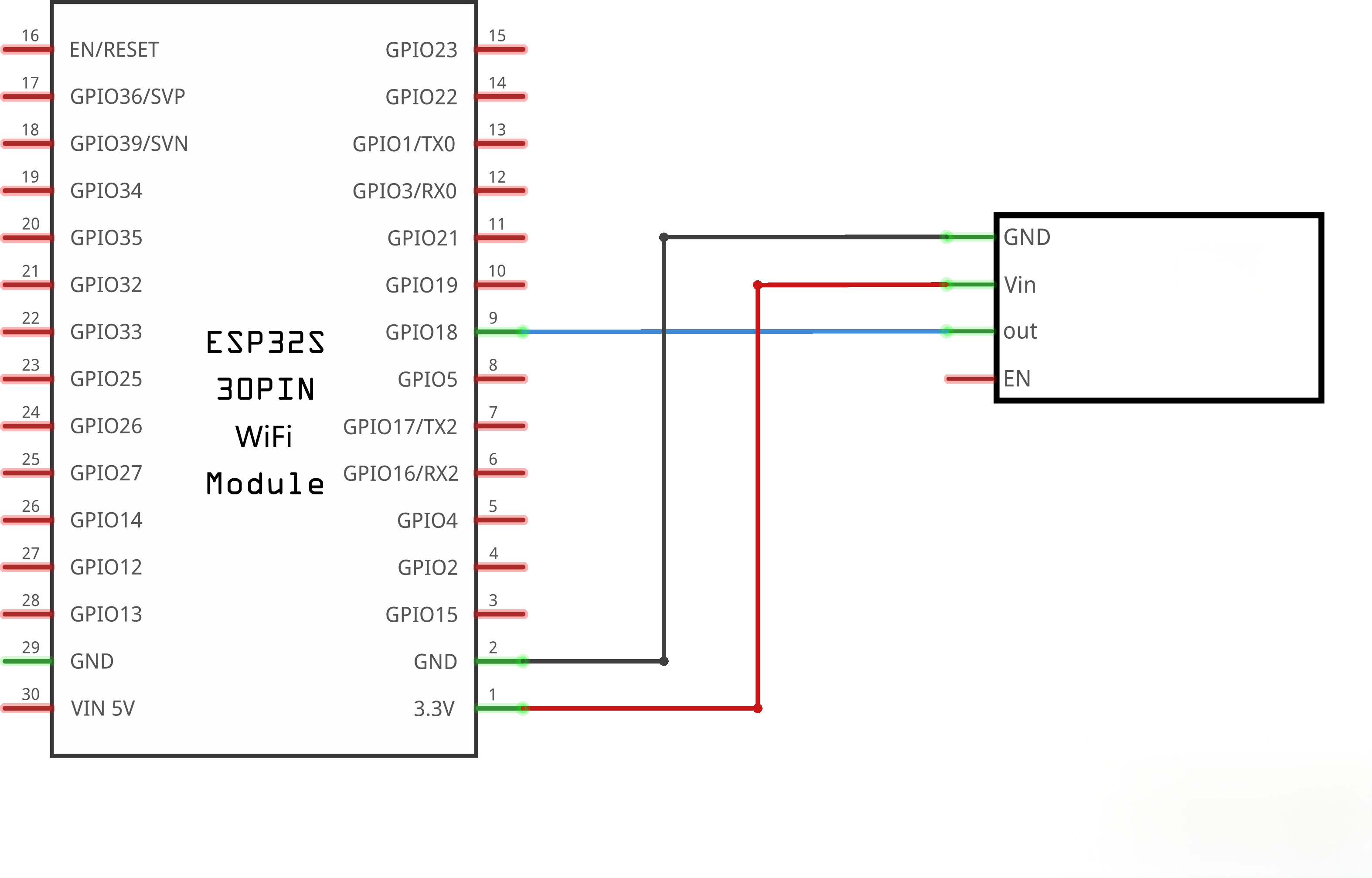
¶ Wiringdiagram
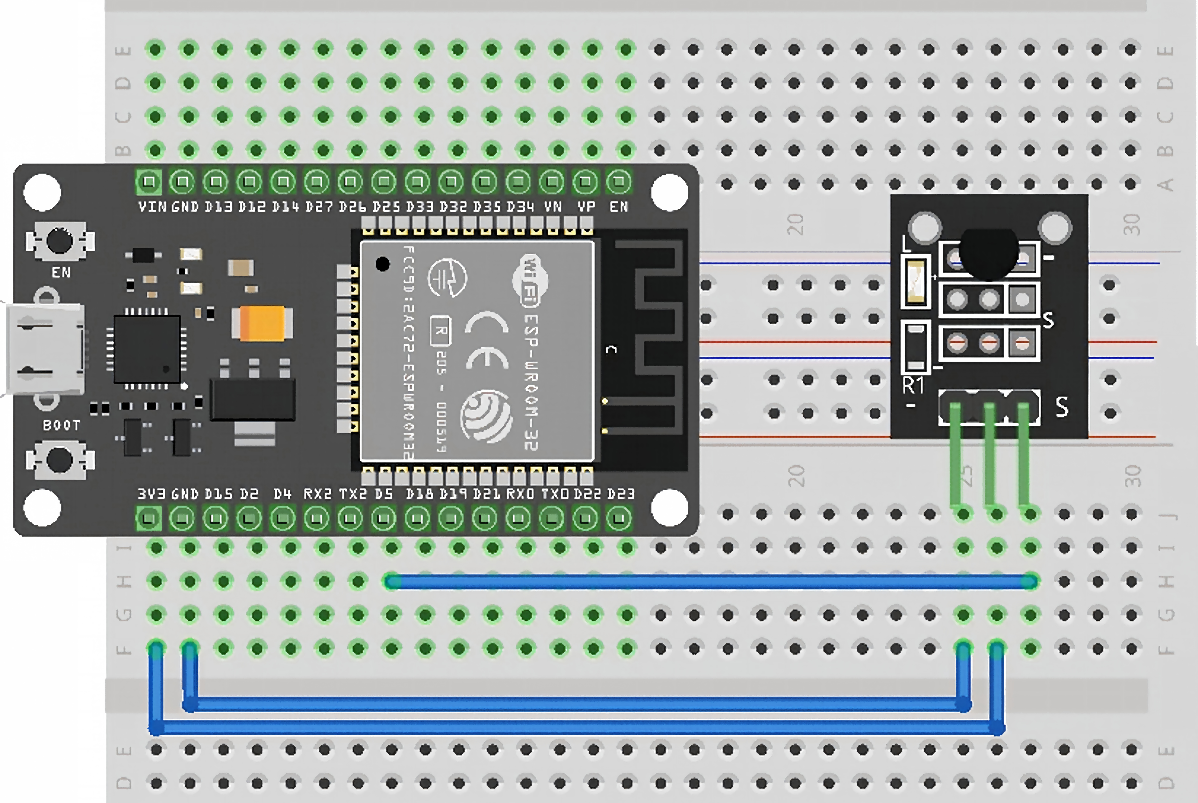
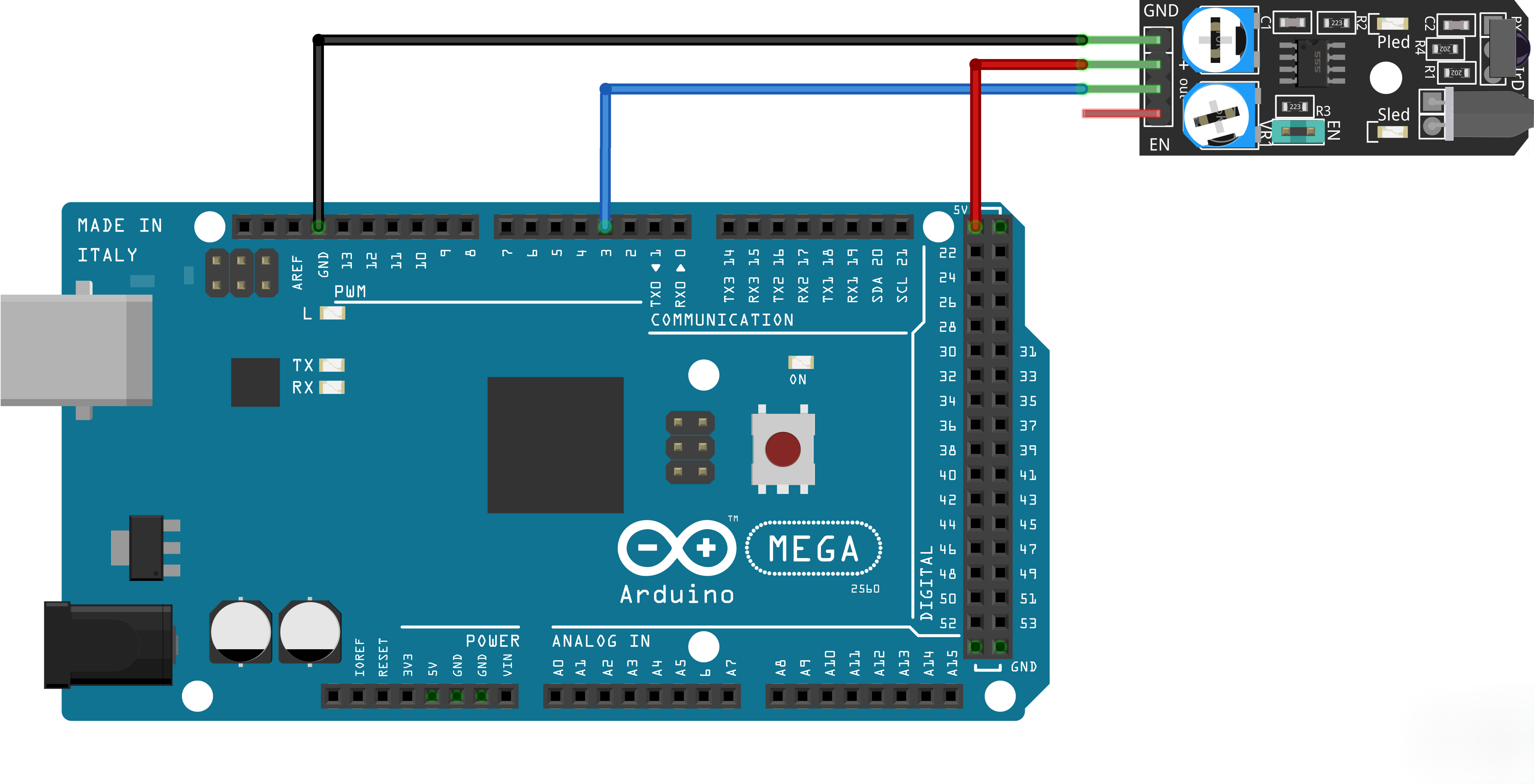
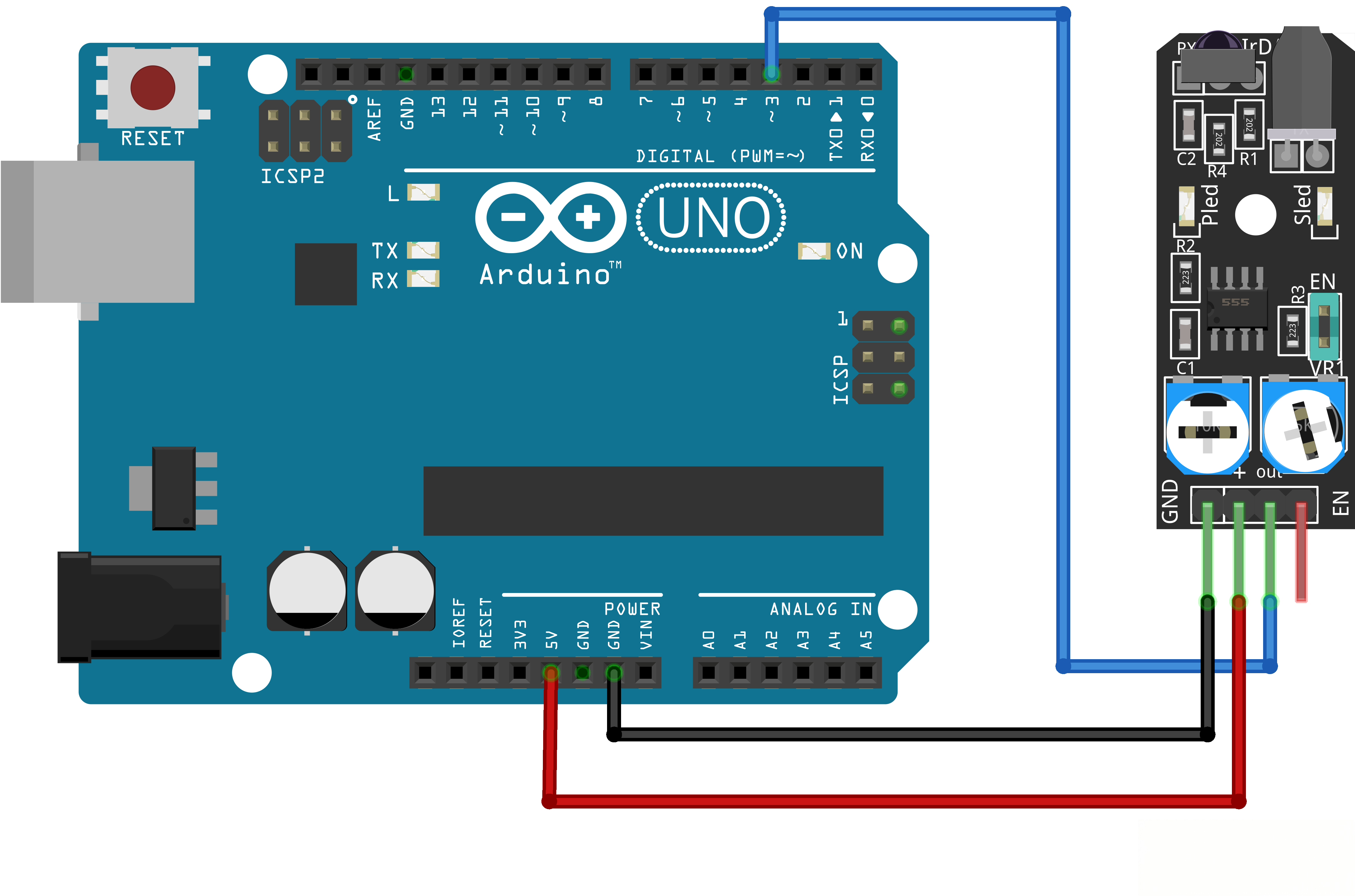
¶ Code
You can click the blue text link to download the program file to your local device, and double-click the file to open it after the download is complete. Please note: Before opening the file, ensure that you have installed the Arduino IDE development environment and completed the installation of relevant components such as the board support package and driver corresponding to the board.
int Led=18; //define LED port
int buttonpin=5; //define switch port
int val; //define digital variable val
void setup()
{
pinMode(Led,OUTPUT);//define LED as a output port
pinMode(buttonpin,INPUT);//define switch as a output port
}
void loop(){ val=digitalRead(buttonpin);//read the value of the digital interface 3 assigned to val
if(val==HIGH)//when the switch sensor have signal, LED blink
{
digitalWrite(Led,HIGH);
}
else
{
digitalWrite(Led,LOW);
}
}
This sensor outputs a high level under normal non-triggered conditions, and the output level switches to a low level once triggered.