¶ IR Receiver
¶ Overview
In this experiment, we will learn how to use Infrared Receiver and IR transmitter module.
In fact now in our daily life they play role in a lot of household electrical appliances are used to this kind of device, such as air conditioning, TV, DVD, etc. Actually it is based on its wireless remote sensing and it is very convenient by using them.
IR Receiver
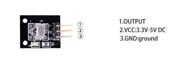
Infrared sensor type 1838 for use with 38 KHz IR signals.
• Supply voltage: 2.7 to 5.5 V
• Frequency: 37.9 KHz
• Receiver range: 18m (typical)
• Receiving angle: 90°
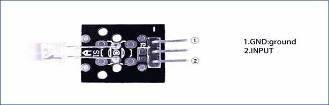
IR Transmitter module
The IR-LED can be used to build a light barrier or an IR remote control signal transmitter.
¶ Component Introduction
¶ IR RECEIVER SENSOR:
IR detectors are little microchips with a photocell that are tuned to listen to infrared light. They are almost always used for remote control detection - every TV and DVD player has one of these in the front to listen for the IR signal from the clicker. Inside the remote control is a matching IR LED, which emits IR pulses to tell the TV to turn on, off or change channels. IR light is not visible to the human eye, which means it takes a little more work to test a setup.
There are a few difference between these and say a CdS Photocells:
IR detectors are specially filtered for IR light, they are not good at detecting visible light. On the other hand, photocells are good at detecting yellow/green visible light, and are not good at IR light.
IR detectors have a demodulator inside that looks for modulated IR at 38 KHz. Just shining an IR LED won't be detected, it has to be PWM blinking at 38KHz. Photocells do not have any sort of demodulator and can detect any frequency (including DC) within the response speed of the photocell (which is about 1KHz)
IR detectors are digital out - either they detect 38KHz IR signal and output low (0V) or they do not detect any and output high (5V). Photocells act like resistors, the resistance changes depending on how much light they are exposed to.
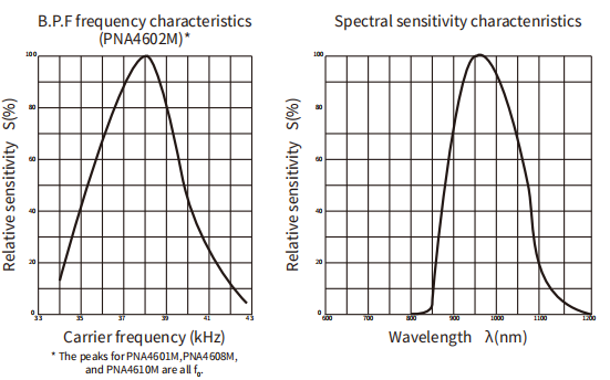
As you can see from these datasheet graphs, the peak frequency detection is at 38 KHz and the peak LED color is 940 nm. You can use from about 35 KHz to 41 KHz but the sensitivity will drop off so that it won't detect as well from afar. Likewise, you can use 850 to 1100 nm LEDs but they won't work as well as 900 to 1000nm so make sure to get matching LEDs! Check the datasheet for your IR LED to verify the wavelength.
Try to get a 940nm - remember that 940nm is not visible light!
Principle
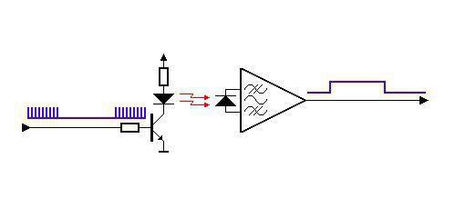
Firstly, let's know the structure of the infrared receiving head: there are two important elements inside the infrared receiving head, IC and PD. IC is receiving head processing components, mainly composed of silicon and circuit. It is a highly integrated device. The main function is filter, plastic, decoding, amplification, etc. PD is a photosensitive diode. The main function is to receive the light signal.
Below is a brief working principle diagram:
¶ Connection Schematic
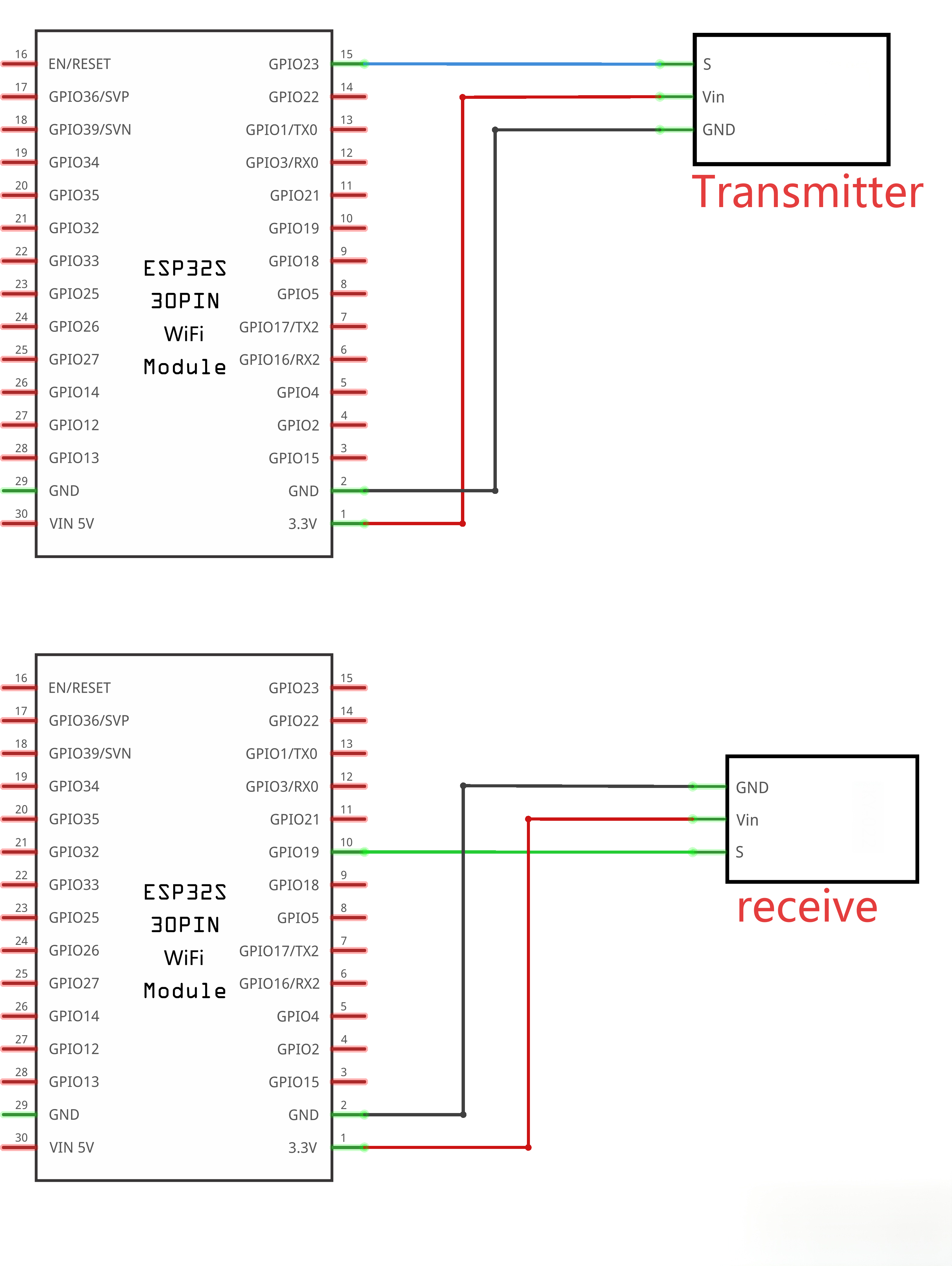
¶ Wiring diagram
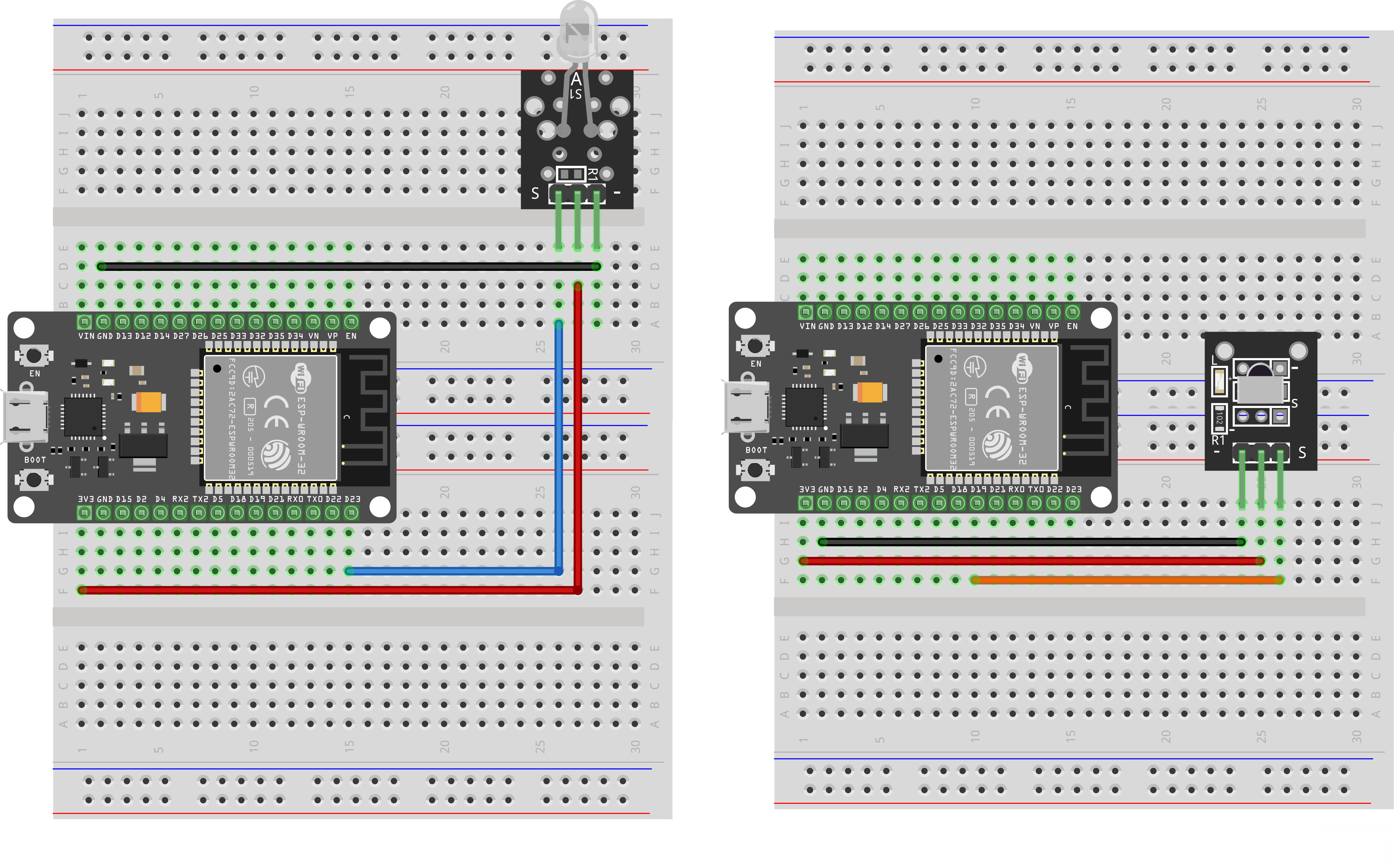
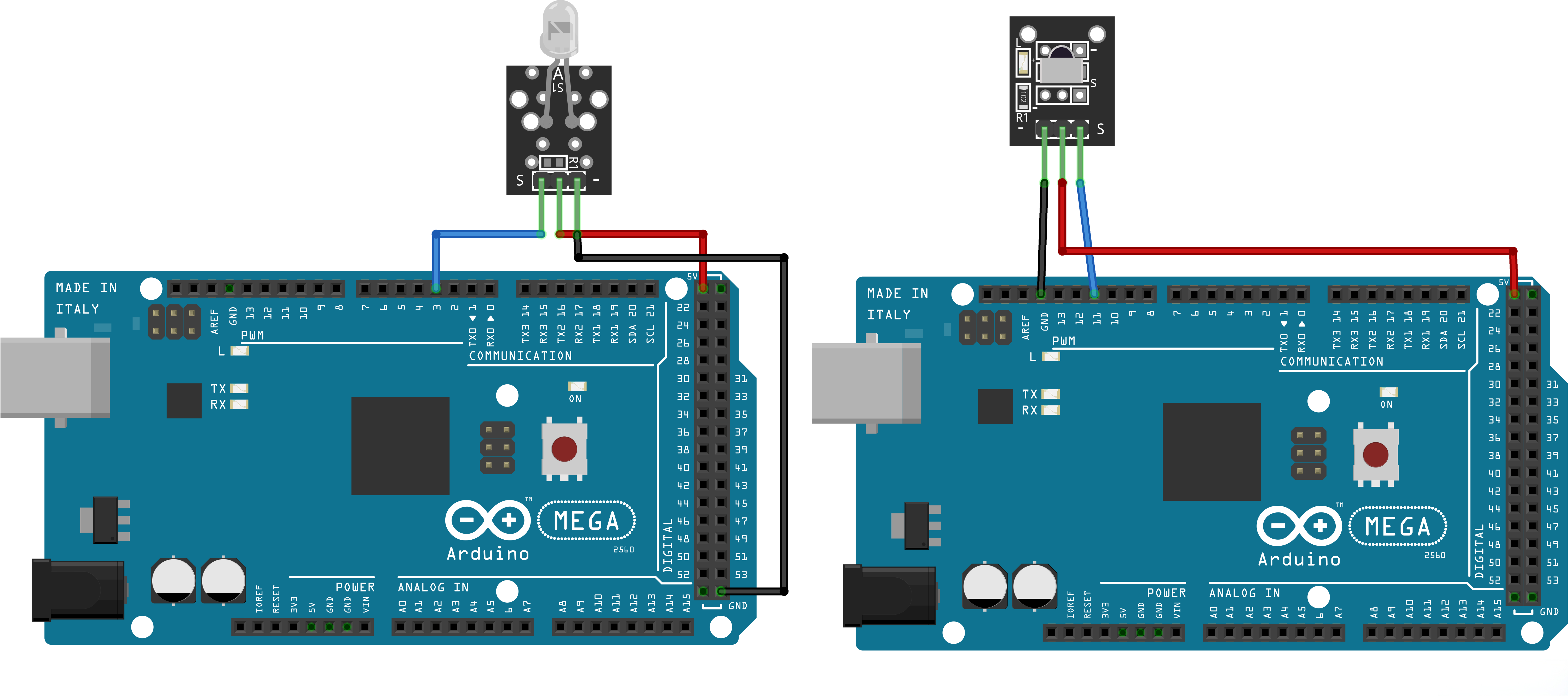
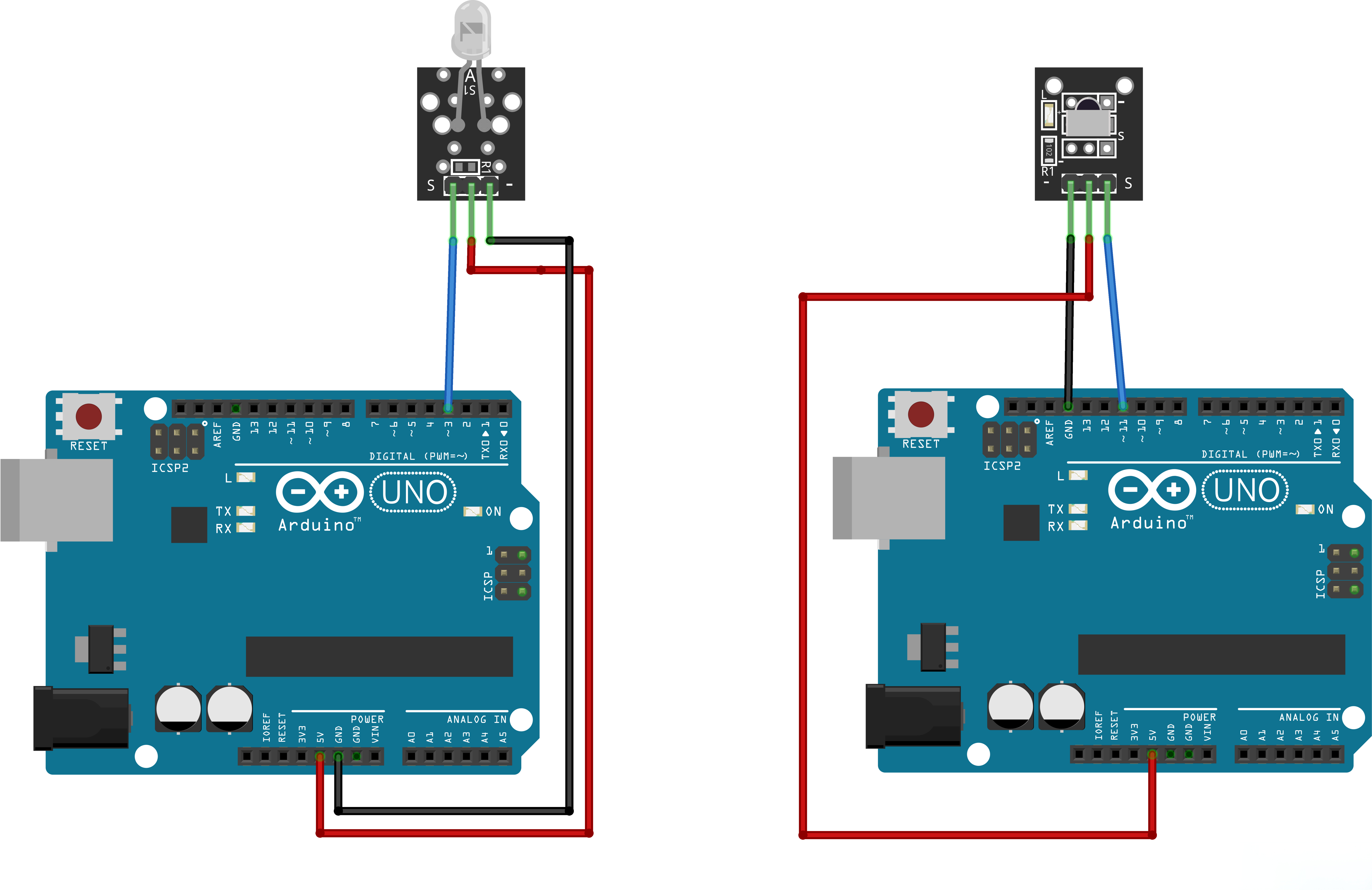
There are 3 connections to the IR Receiver.
The connections are: Signal, Voltage and Ground.
The“G”is the Ground,“Y”is signal, and“R”is Voltage 3.3V.
¶ Code
You can click the blue text link to download the program file to your local device, and double-click the file to open it after the download is complete. Please note: Before opening the file, ensure that you have installed the Arduino IDE development environment and completed the installation of relevant components such as the board support package and driver corresponding to the ESP32 development board.
¶ ESP32 Infrared Remote Control Tutorial
This tutorial contains complete code examples for ESP32 infrared receiver and transmitter, implementing NEC and RC5 infrared protocol reception and transmission using the IRremote library.
¶ 1. Infrared Receiver (IR_Receiver.ino)
This code implements an infrared signal receiver that can decode received infrared signals and control the built-in LED based on the received data.
#include <IRremote.hpp>
#define RECV_PIN 19
#define LED 2
Pin Configuration:
RECV_PIN (19): Defines the input pin for the infrared receiver module as GPIO 19LED (2): Defines the built-in LED pin on the ESP32 development board as GPIO 2
void setup()
{
pinMode(LED, OUTPUT);
Serial.begin(9600);
IrReceiver.begin(RECV_PIN, DISABLE_LED_FEEDBACK);
}
setup() Function: Initializes system configuration.
pinMode(LED, OUTPUT): Sets the LED pin to output mode for indicating receiving statusIrReceiver.begin(RECV_PIN, DISABLE_LED_FEEDBACK):- Initializes the infrared receiver, connected to the specified pin
DISABLE_LED_FEEDBACK: Disables hardware LED feedback, uses software to control LED- Starts infrared signal monitoring
void loop()
{
if (IrReceiver.decode())
{
int state;uint32_t recvValue = IrReceiver.decodedIRData.decodedRawData; if (recvValue == 1) { state = HIGH; } else { state = LOW; } digitalWrite(LED, state); Serial.println(recvValue-256); IrReceiver.resume();}
}
loop() Function: Main loop that continuously monitors and decodes infrared signals.
1. Signal Detection Module:
if (IrReceiver.decode())
- Calls the
decode()function to check for new infrared signals - Returns true if a complete infrared signal is successfully decoded
- Returns false if no signal is detected or decoding fails
2. Data Processing Module:
uint32_t recvValue = IrReceiver.decodedIRData.decodedRawData;
if (recvValue == 1)
{
state = HIGH;
}
else
{
state = LOW;
}
-
uint32_t recvValue:- Declares a 32-bit unsigned integer variable
recvValueto store decoded raw data uint32_tis an unsigned 32-bit integer type with a range from 0 to 4,294,967,295- Can store complete infrared protocol data frames
- Declares a 32-bit unsigned integer variable
-
IrReceiver.decodedIRData.decodedRawData:IrReceiver.decodedIRDatais a structure containing all related information decoded by the IRremote librarydecodedRawDatais a member variable of this structure that stores the decoded raw data value- This data is infrared signal data that has been parsed and verified by the IRremote library
- Contains address codes, command codes, and other information presented as integer values
-
if (recvValue == 1)Conditional Logic:- Checks if the received data equals 1
- If the value is 1, sets LED state to HIGH (turns on)
- Otherwise sets LED state to LOW (turns off)
- Controls LED switching through this simple logic
-
Data Storage Characteristics:
decodedRawDatastores values after protocol parsing- The meaning of this value may differ for different infrared protocols
- RC5 protocol typically includes device address and control code
3. Output and Recovery Module:
digitalWrite(LED, state);
Serial.println(recvValue-256);
IrReceiver.resume();
-
digitalWrite(): Writes the processed state to the LED pin to control LED on/off -
Serial.println(recvValue-256):- Outputs received data to the Serial Monitor
- Reason for subtracting 256:
- When processing RC5 protocol, the IRremote library performs bitwise OR operation on received data with 0x100 (256)
- This is an internal data processing mechanism of the library to distinguish between different types of data bits
- When the sender transmits 0x00, the receiver actually receives 0x100 (256)
- When the sender transmits 0x01, the receiver actually receives 0x101 (257)
- After subtracting 256, the output displays the original transmitted data (0 and 1)
- This clearly shows the actual value sent by the transmitter
- Data Conversion Examples:
- Received value 257 - 256 = 1
- Received value 256 - 256 = 0
- This processing method makes debugging and verifying data more intuitive
-
IrReceiver.resume(): Recovers the receiver state to prepare for receiving the next infrared signal
¶ 2. Infrared Transmitter (IR_Transmitter.ino)
This code implements an infrared signal transmitter that can continuously send RC5 protocol infrared signals.
#include <IRremote.hpp>
#define IR_SEND_PIN 23
Pin Configuration:
IR_SEND_PIN (23): Defines the connection pin for the infrared transmitting LED as GPIO 23
void setup()
{
Serial.begin(9600);
IrSender.begin(IR_SEND_PIN);
Serial.println("Infrared Transmitter Started, Sending 0x00 and 0x01 in Loop");
}
setup() Function: Initializes transmitter configuration.
Serial.begin(9600): Initializes serial communication at 9600 baud rateIrSender.begin(IR_SEND_PIN):- Initializes the infrared transmitter
- Configures the specified pin as infrared signal output
- Prepares to send infrared signals
- Outputs startup message to the Serial Monitor
loop() Function: Main loop that continuously sends infrared signals.
IrSender.sendRC5(0x00, 8);
delay(200);
IrSender.sendRC5(0x01, 8);
delay(200);
IrSender.sendRC5(0x00, 8): Sends RC5 protocol infrared signal- First parameter: Data to send (0x00)
- Second parameter: Number of data bits (8 bits)
IrSender.sendRC5(0x01, 8): Sends RC5 infrared signal with data 0x01- Continuously alternates between sending 0x00 and 0x01, forming a pulse sequence
¶ 3. Hardware Connection Guide
¶ Infrared Receiver Connection
- VS1838B Infrared Receiver Module:
- VCC → 3.3V
- GND → GND
- OUT → GPIO 19
¶ Infrared Transmitter Connection
- Infrared Transmitting LED:
- Positive terminal (anode) → GPIO 23
- Negative terminal (cathode) → GND (with appropriate current-limiting resistor in series)
¶ LED Indicator
- Built-in LED → GPIO 2
¶ 4. Key Functions Reference
¶ IRremote Library Functions
Receiver Functions:
IrReceiver.begin(pin, feedback): Initializes the infrared receiverIrReceiver.decode(): Detects and decodes infrared signalsIrReceiver.decodedIRData.decodedRawData: Gets the decoded raw dataIrReceiver.resume(): Recovers the receiver to receive the next signal
Transmitter Functions:
IrSender.begin(pin): Initializes the infrared transmitterIrSender.sendRC5(data, nbits): Sends RC5 protocol signal- RC5 protocol is an infrared remote control protocol developed by Philips
- Uses Manchester encoding
- Commonly used for TV, audio equipment remote controls
¶ Arduino Basic Functions
pinMode(pin, mode): Sets pin mode (INPUT/OUTPUT)digitalWrite(pin, value): Writes HIGH or LOW to a digital pinSerial.begin(baudrate): Initializes serial communicationSerial.println(data): Sends data to serial port with newlinedelay(ms): Delays for specified milliseconds
¶ Testing Steps
- Confirm that both the infrared transmitter and infrared receiver are correctly wired to the corresponding pins.
- Upload the matched transmitter and receiver programs to the two ESP32 boards respectively.
- Open the serial monitor to check whether there is serial output and verify if the output content is correct.
- Infrared light is invisible to the naked eye, so the transmitting status cannot be observed directly. The onboard red LED of the infrared receiver module will light up once an infrared signal is received, which you can use for inspection.