¶ Overview
In this tutorial, you will master the usage of the DHT11 temperature and humidity sensor and the water
level sensor, and be able to accurately collect temperature, humidity, and water level data in the current
environment. These data can be used to simulate core monitoring indicators such as temperature, humidity, and precipitation required by a weather station.
¶ Component Required:
(1) x Elegoo ESP32
(2) x 400-hole breadboards
(1) x DHT11 Temperature and Humidity module
(1) x water level sensor
(1) x 0.96 OLED display
¶ Component Introduction
¶ Temp and humidity sensor:
DHT11 digital temperature and humidity sensor is a composite Sensor which contains a calibrated digital signal output of the temperature and humidity. The dedicated digital modules collection technology and the temperature and humidity sensing technology are applied to ensure that the product has high reliability and excellent long-term stability. The sensor includes a resistive moisture sensor and a NTC temperature measurement devices, and connects with a high-performance 8-bit microcontroller.
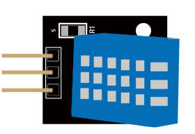
Applications:HVAC, dehumidifier, testing and inspection equipment, consumer goods, automotive, automatic control, data loggers, weather stations, home appliances, humidity regulator, medical and other humidity measurement and control.
Product parameters
| Humidity Parameters | |
|---|---|
| Parameter | Specification |
| Relative humidity | 1m / s air 6s Hysteresis: |
| Resolution | 8Bit |
| Repeatability | ±1% RH |
| Accuracy | At 25°C ±5% RH |
| Long-term stability | < ±0.5% RH / yr in |
| Interchangeability | fully interchangeable |
| Response time | 1 / e (63%) of 25°C 6s |
| Temperature Parameters | |
|---|---|
| Parameter | Specification |
| Response time | 1 / e (63%) 10S |
| Resolution | 8Bit |
| Repeatability | ±0.2°C |
| Range | At 0°C ±50°C |
| Power supply | DC 3.5~5.5V |
| Supply Current | measurement 0.3mA standby 60μA |
| Sampling period | more than 2 seconds |
Pin Description:
- the VDD power supply 3.5~5.5V DC.
- DATA serial data, a single bus.
- GND ground, the negative power.
¶ Water Level sensor
A water sensor brick is designed for water detection, which can be widely used in sensing the rainfall, water level, even the liquate leakage. The brick is mainly composed of three parts: an electronic brick connector, a 1 MΩ resistor, and several lines of bare conducting wires.
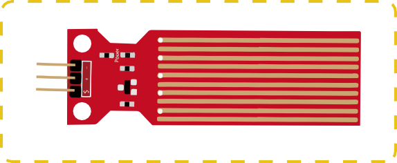
Interlaced between the grounded traces are the sense traces.
The sensor traces have a weak pull-up resistor of 1 MΩ. The resistor will pull the sensor trace value
high until a drop of water shorts the sensor trace to the grounded trace. Believe it or not this circuit will work with the digital I/O pins of your UNO/ESP32 board or you can use it with the analog pins to detect the amount of water induced contact between the grounded and sensor traces.
This item can judge the water level through with a series of exposed parallel wires stitch to measure the water droplet/water size. It can easily change the water size to analog signal, and output analog value can directly be used in the program function, then to achieve the function of water level alarm.
It has low power consumption, and high sensitivity.
¶ Features:
- Working voltage: 5V
- Working Current: <20ma
- Interface: Analog
- Width of detection: 40mm×16mm
- Working Temperature: 10℃~30℃
- Output voltage signal: 0~2.4V
¶ I2C OLED Display
The organic light-emitting diode (OLED) display that we’ll use in this tutorial is the SSD1306 model: a monocolor, 0.96-inch display with 128×64 pixels as shown in the following figure.
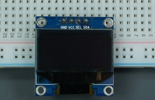
The model we’re using here has only four pins and communicates with the ESP32 using I2C communication protocol. There are models that come with an extra RESET pin. There are also other OLED displays that communicate using SPI communication.
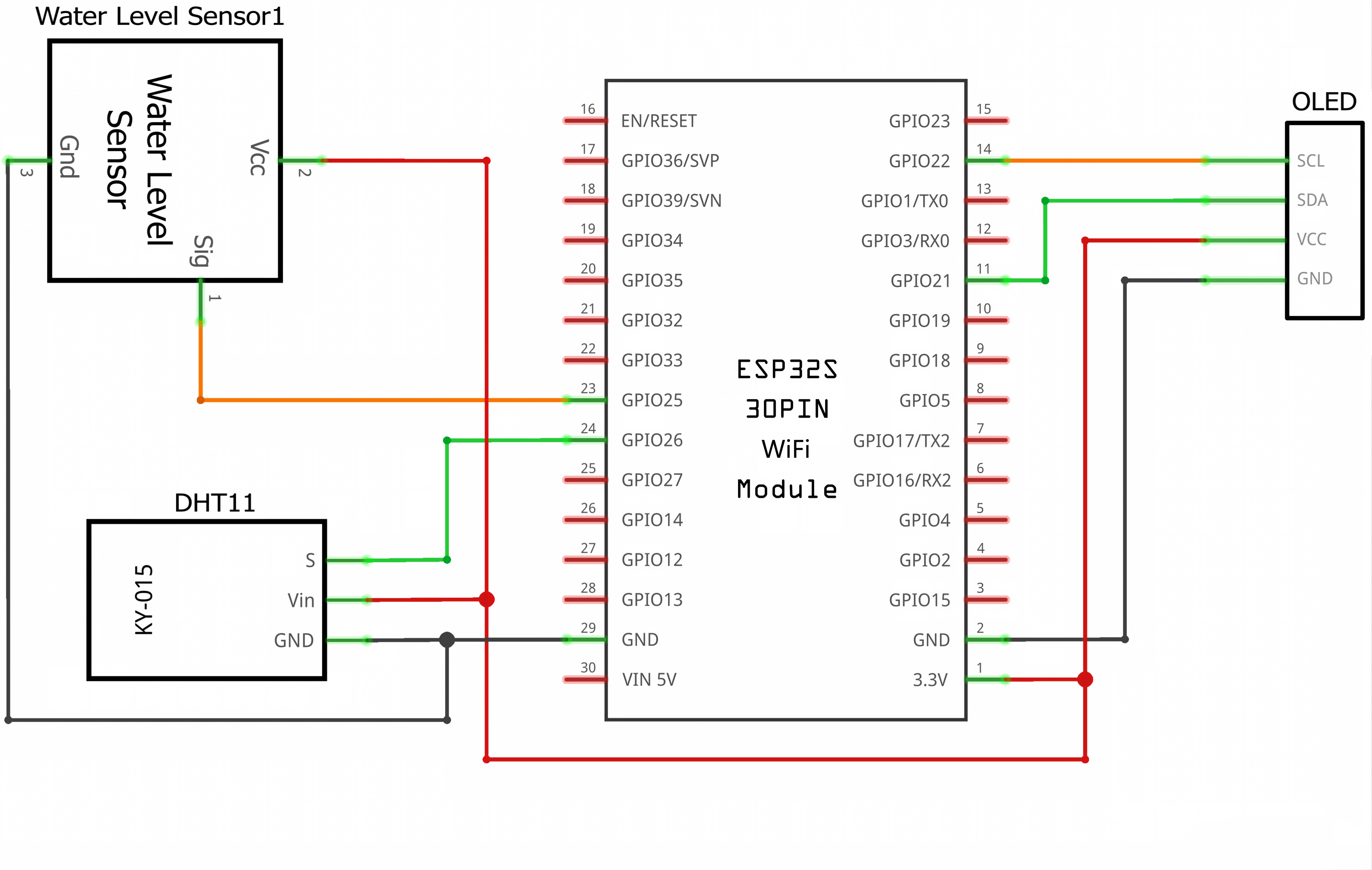
Because the OLED display uses I2C communication protocol, wiring is very simple. You just need to connect to the ESP32 I2C pins as D21(SDA)、D22(SCL)
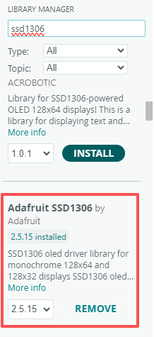
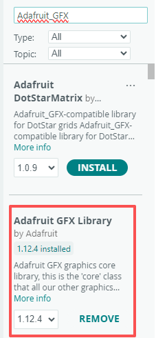
To control the OLED display you need the adafruit_SSD1306.h and the adafruit_GFX.h libraries. Follow the next instructions to install those libraries.
- Open your Arduino IDE and go to Sketch > Include Library > Manage Libraries. The Library Manager should open.
- Type “SSD1306” in the search box and install the SSD1306 library from Adafruit.
¶ Tips for writing text using these libraries
Here’s some functions that will help you handle the OLED display library to write text or draw simple graphics.
- display.clearDisplay() – all pixels are off
- display.drawPixel(x,y, color) – plot a pixel in the x,y coordinates
- display.setTextSize(n) – set the font size, supports sizes from 1 to 8
- display.setCursor(x,y) – set the coordinates to start writing text
- display.print(“message”) – print the characters at location x,y
- display.display() – call this method for the changes to make effect
¶ Connection Schematic
¶ Wiring diagram
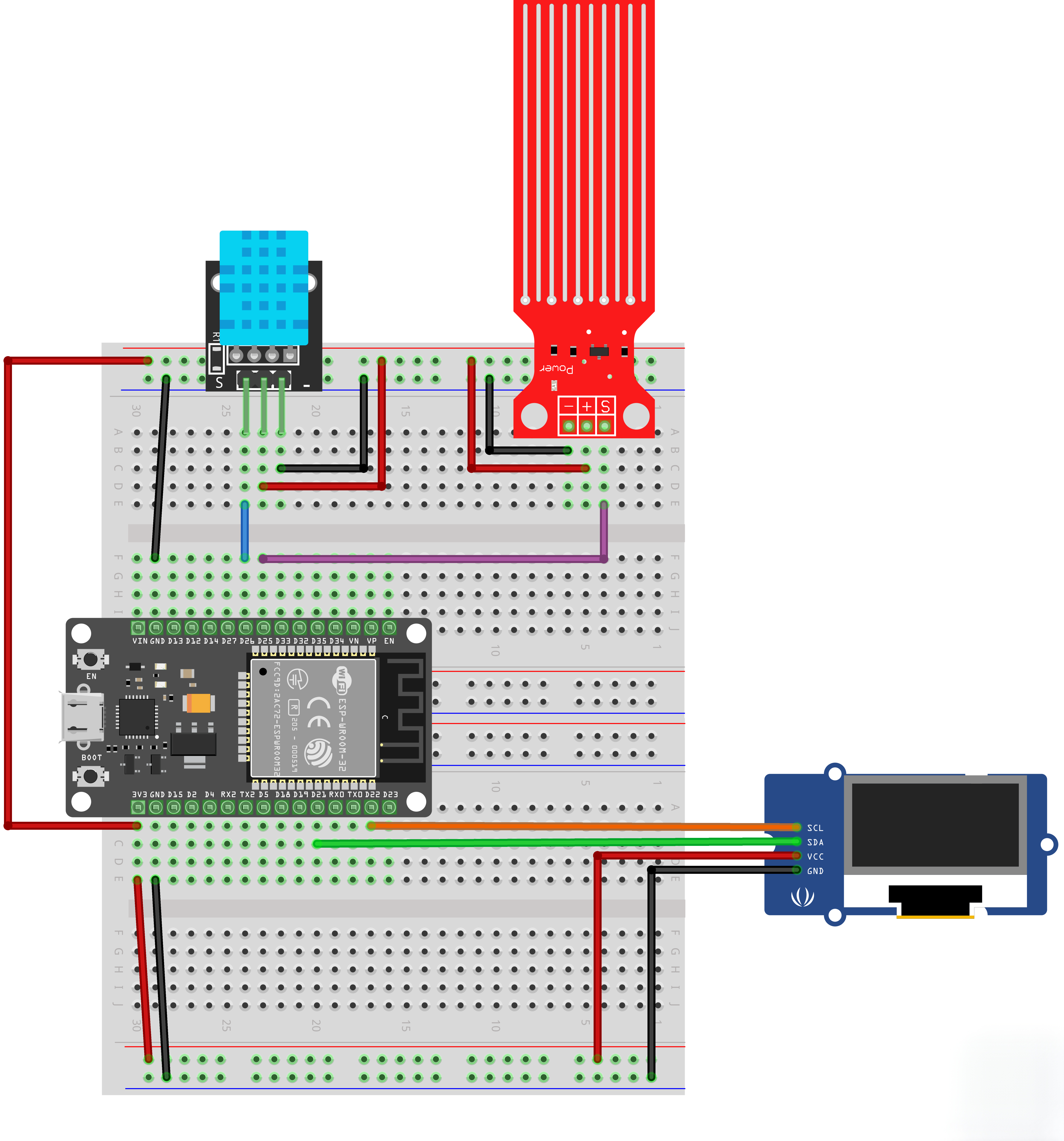
¶ Code
After wiring, please open the program in the code folder- weather station and click UPLOAD to upload the
program. Before you can run this, make sure that you have installed the library or re-install it, if necessary. Otherwise, your code won't work.This library is stored in the provided folder and needs to be manually imported and added to your project. Please refer to the link below for specific operation methods.
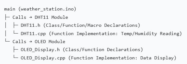
After opening the program, you will see multiple files, including the .ino main program file, .h header files, and .cpp source files. This program is a weather station data collection and display system, whose core function is to read temperature and humiditydata via the DHT11 sensor, collect water leveldata through the water level sensor, and displayall data on the OLED screen in real time. The module call relationship of each file is shown inthe figure below.
Note: The water level sensor can work by directly reading the analog pin values, so no separate resource files are required.
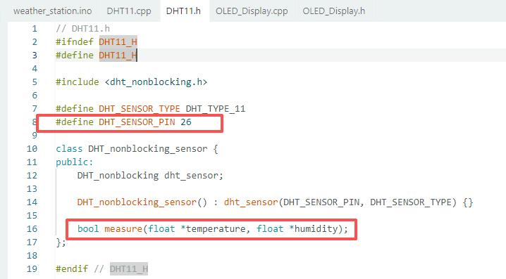
In the .h header files, there usually include function declarations, definitions of input/output pins, macro
definitions, and declarations of relevant data types. By reading the header files, you can quickly grasp the
core functions of the corresponding module, the external calling interfaces it provides, and hardware
dependencies (such as pin configurations) without checking the specific implementatio details.
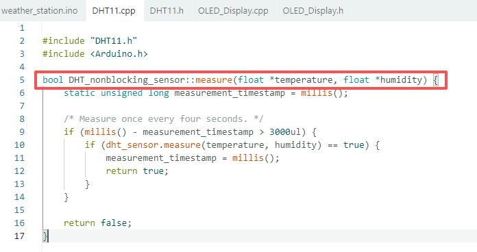
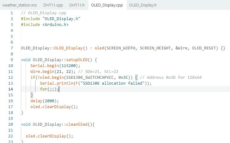
Similarly, the .cpp source files serve as the implementation carrier for the header files. Their core function is to implement the function logic declared in the .h files, as well as complete variable definitions and initialization. They contain specific code execution processes (such as sensor data reading timing, OLED screen drawing logic, etc.) and are the actual implementers of module functions. Without modifying the header files, you can optimize module performance or adjust functional details only by modifying the code in .cpp files, without affecting the calling interfaces of other modules.
¶ Common Pitfalls
-
Member Variable-Function Name Collision:
The OLED instance name must avoid display (which conflicts with the display() refresh function in the Adafruit_SSD1306 library). While the current name oled circumvents this, renaming it to display by mistake will cause compilation errors. -
Mismatched I2C Pins or Device Address:
The SDA/SCL pins bound in Wire.begin(21, 22) must match the hardware wiring, and the address 0x3C in oled.begin() must be adjusted based on the OLED module model(some use 0x3D). A mismatch will trigger the "SSD1306 allocation failed" error and force the program into an infinite loop.
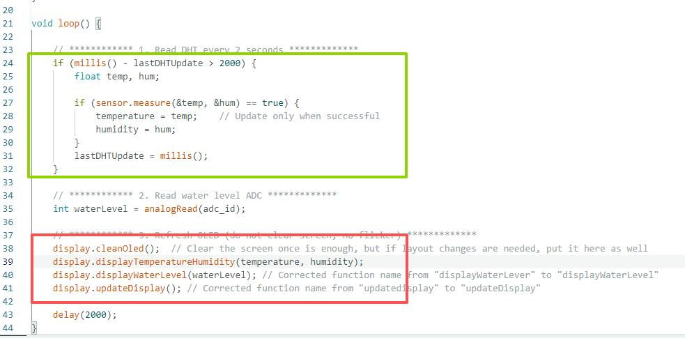
Since the DHT11 sensor collects data once every 2 seconds and returns valid results only when the reading
is successful, special attention must be paid to the persistent display logic of the data: the key is to reasonably plan the calling positions of the screen-clearing function (cleanOled()) and the display refresh function (updatedisplay()). It is recommended to execute the screen-clearing operation at the start of each loop, and call the unified refresh function only after all data (temperature, humidity, water level) have been written to thedisplay buffer.
This process of "clearscreen first → write all data → unified refresh" can avoid screen flickering caused
by refreshing before partial data is written, and ensure that historical valid data will not disappear arbitrarily when the sensor reading fails, achieving a stable and persistent display effect.
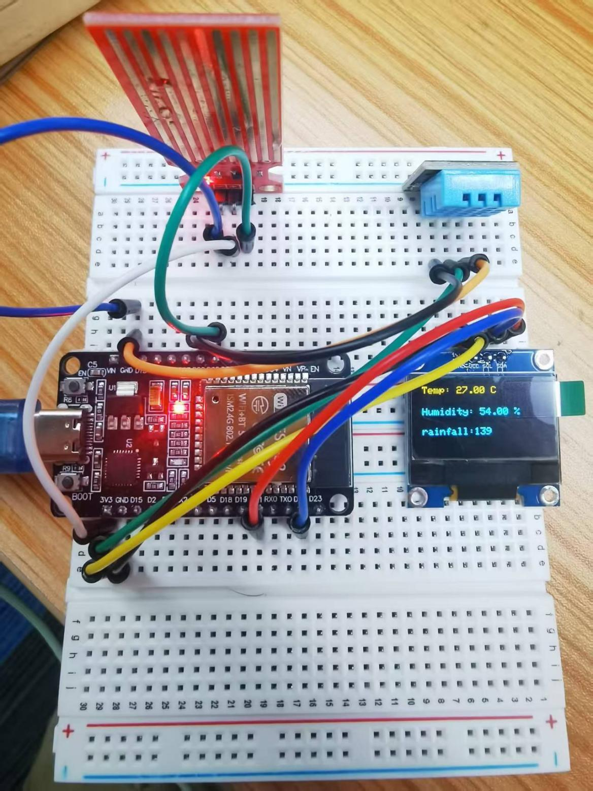
Upload the program then open the monitor, we can see the data as below:
(It shows the temperature of the environment, we can see it is 27 to 25 degrees with 45.0% humidity)
Click the Serial Monitor button to turn on the serial monitor. The basics about the serial monitor are
introduced in details in part 2 Lesson 4.
If you have any questions about the code, please refer to the link below.
https://wiki.elegoo.com/oshw-getting-started-%26-kits/dht11
https://wiki.elegoo.com/oshw-getting-started-%26-kits/watersensor-uno
https://wiki.elegoo.com/oshw-getting-started-%26-kits/oled