¶ OLED
¶ Overview
In this tutorial, shows how to use the SSD1306 0.96 inch I2C OLED display with the ESP32. We’ll show you some features of the OLED display, how to connect it to the ESP32 board, and how to write text.
¶ Component Required:
(1) x Elegoo ESP32
(1) x I2C OLED Display
(2) x 400 Tie Points Breadboard
(4) x M-Mwires (Male to Male jumper wires)
¶ Component Introduction
¶ I2C OLED Display
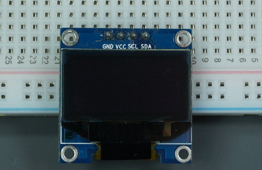
The organic light-emitting diode (OLED) display that we’ll use in this tutorial is the SSD1306 model: a monocolor, 0.96-inch display with 128×64 pixels as shown in the following figure.
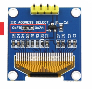
Q1: The I2C scanner reads the address 0x78. Should I use 0x78 directly in the code?
A: Do NOT use 0x78 directly!
0x78 is the 8-bit I2C write address (the least significant bit is the read/write control bit).
Shift it right by 1 bit: 0x78 >> 1 = 0x3C. 0x3C is the 7-bit device address required by most libraries.
Popular OLED libraries for Arduino and ESP32 (U8G2, Adafruit_SSD1306, SSD1306Wire) all accept the 7-bit address 0x3C.
Wrong usage: display.begin(0x78); → The OLED screen will not light up
Correct usage: display.begin(0x3C);
Q2: When to use address 0x3C, and when to use 0x3D?
A: The address is determined by the logic level of pin SA0 on the PCB (hardware feature of SSD1306):
-
SA0 pulled LOW (90% of common 0.96-inch OLED modules on the market)
7-bit address: 0x3C | 8-bit write address: 0x78 -
SA0 pulled HIGH (a small number of revised modules)
7-bit address: 0x3D | 8-bit write address: 0x7A
Most modules reserve the SA0 solder pad. Shorting this pad switches the I2C address, allowing two OLED screens to be connected to the same I2C bus simultaneously.
The OLED display doesn’t require backlight, which results in a very nice contrast in dark environments. Additionally, its pixels consume energy only when they are on, so the OLED display consumes less power when compared with other displays.
The model we’re using here has only four pins and communicates with the ESP32 using I2C communication protocol. There are models that come with an extra RESET pin. There are also other OLED displays that communicate using SPI communication.
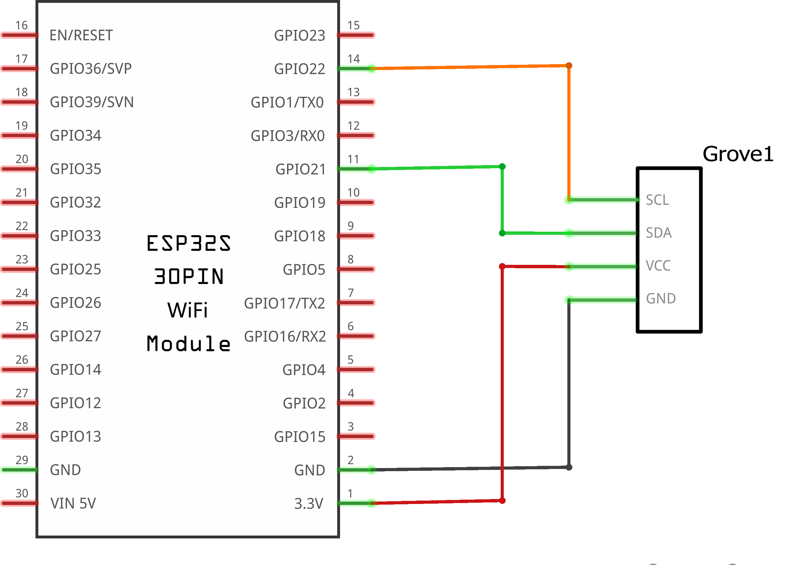
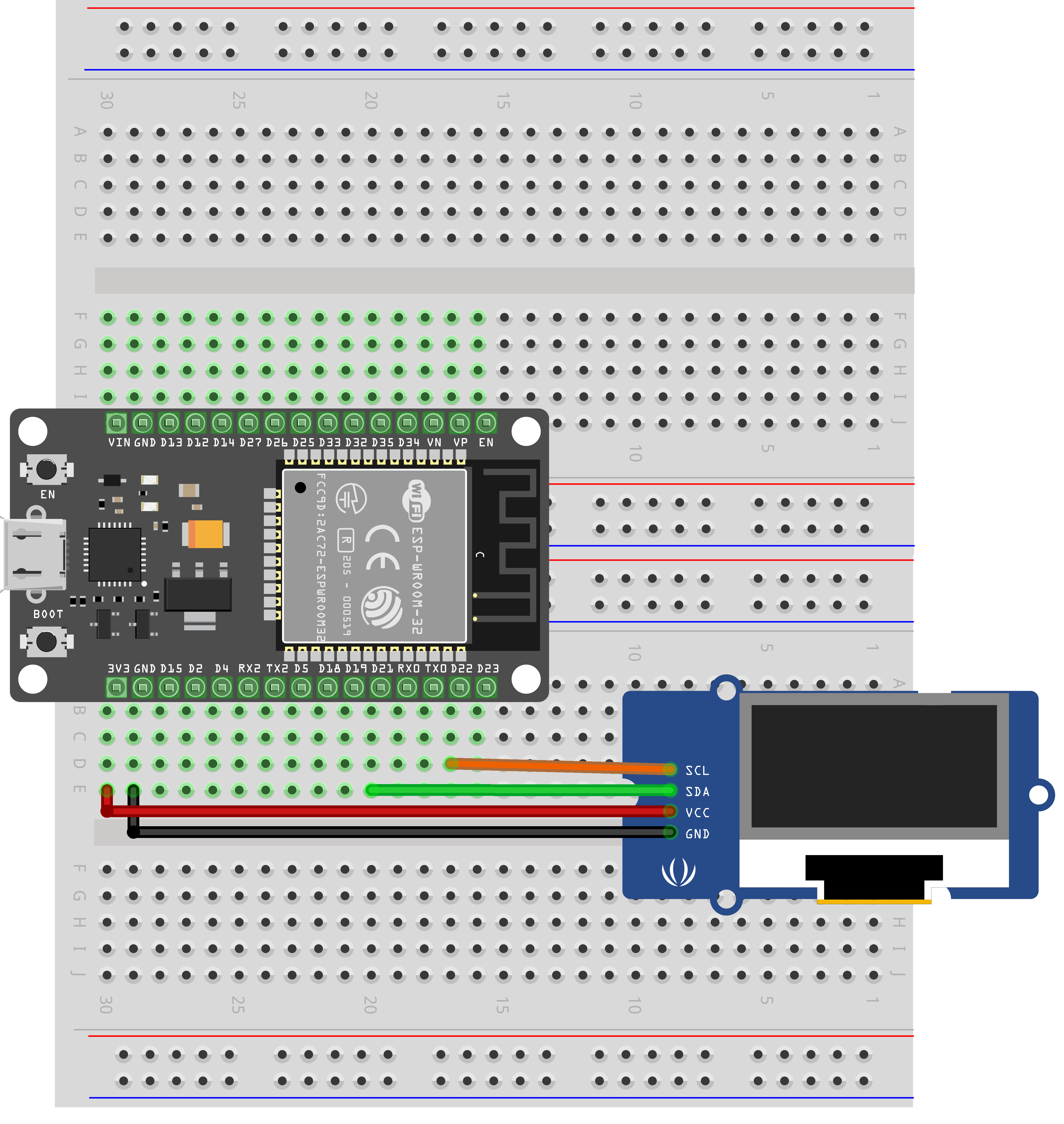
Because the OLED display uses I2C communication protocol, wiring is very simple. You just need to connect to the ESP32 I2C pins as D21(SDA)、D22(SCL)
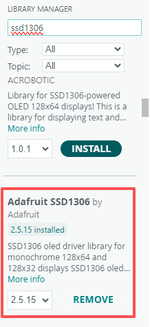
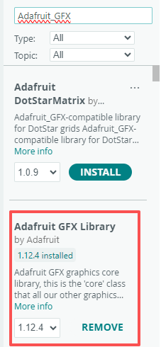
To control the OLED display you need the adafruit_SSD1306.h and the adafruit_GFX.h libraries. Follow the next instructions to install those libraries.
- Open your Arduino IDE and go to Sketch > Include Library > Manage Libraries. The Library Manager should open.
- Type “SSD1306” in the search box and install the SSD1306 library from Adafruit.
¶ Tips for writing text using these libraries
Here’s some functions that will help you handle the OLED display library to write text or draw simple graphics.
- display.clearDisplay() – all pixels are off
- display.drawPixel(x,y, color) – plot a pixel in the x,y coordinates
- display.setTextSize(n) – set the font size, supports sizes from 1 to 8
- display.setCursor(x,y) – set the coordinates to start writing text
- display.print(“message”) – print the characters at location x,y
- display.display() – call this method for the changes to make effect
¶ Connection Schematic
¶ Wiring diagram
¶ Code
After wiring the OLED display to the Arduino and installing all required libraries, you can use one example from the library to see if everything is working properly.
In your Arduino IDE, go to File > Examples > Adafruit SSD1306 and select the example for the display you’re using.
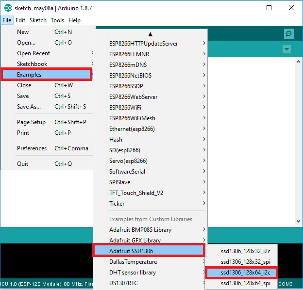
On ESP32, the I²C pins (SDA & SCL) can be freely remapped to any available GPIOs; you must explicitly call Wire.begin(SDA, SCL). The example wires the OLED to GPIO 21 for SDA and GPIO 22 for SCL—unlike the fixed A4/SDA and A5/SCL on Arduino UNO—adjust as required.
Wire.begin(21,22);
If nothing is displayed on the OLED after uploading the code, check the wiring first. After confirming the wiring is correct, modify the corresponding I2C address in the code. The default I2C address of this OLED module is 0x3C.
#define SCREEN_ADDRESS 0x3C ///< See datasheet for Address; 0x3D for 128x64, 0x3C for 128x32
You can click the blue text link to download the program file to your local device, and double-click the file to open it after the download is complete.
Please note: Before opening the file, ensure that you have installed the Arduino IDE development environment and completed the installation of relevant components such as the board support package and driver corresponding to the ESP32 development board. If you have any questions about this operation process, you can refer to the "part 1" chapter of the document for detailed guidance.