¶ Tools and Materials
- A 2.0 mm Allen key
- A 2.5 mm Allen key
- A 3.0 mm Allen key
- A 4.0 mm Allen key
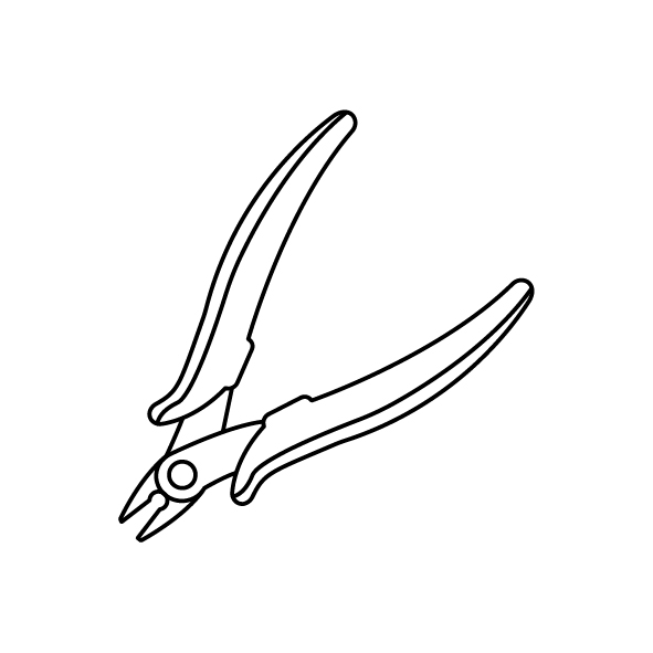
- A pair of diagonal pliers
- Cable ties
- A new spring wire
¶ Tutorial Video
Coming soon.
¶ Instruction
- Power off the printer and unplug the power cord.
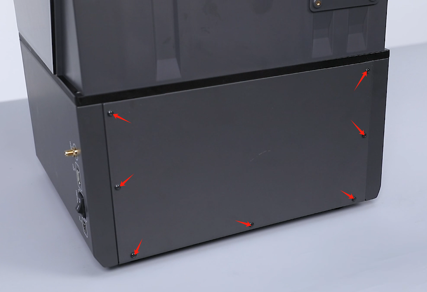
- Loosen the 7 screws securing the back cover of the printer using a 2.0 mm Allen key and remove the back cover.

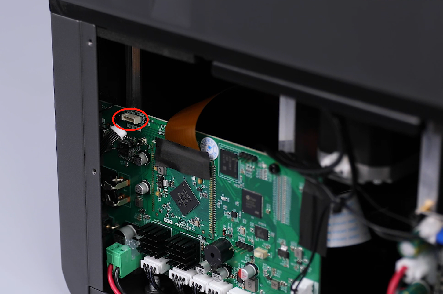
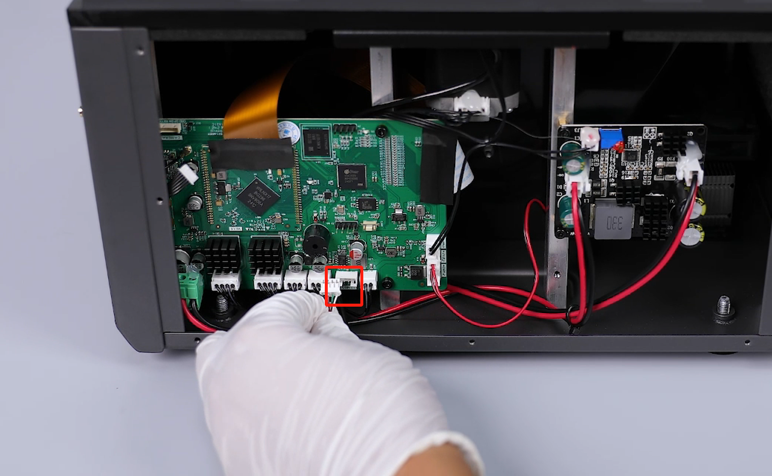
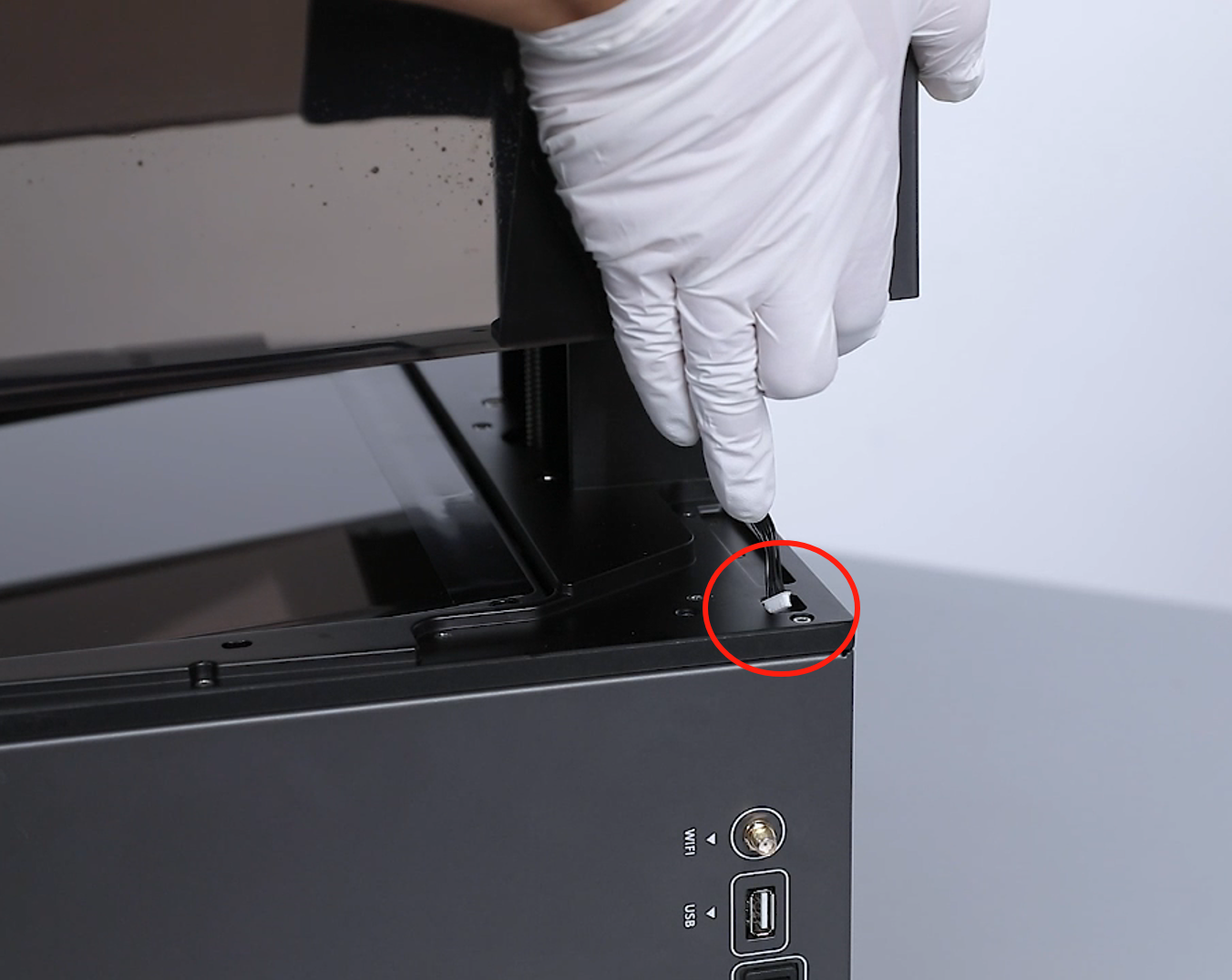
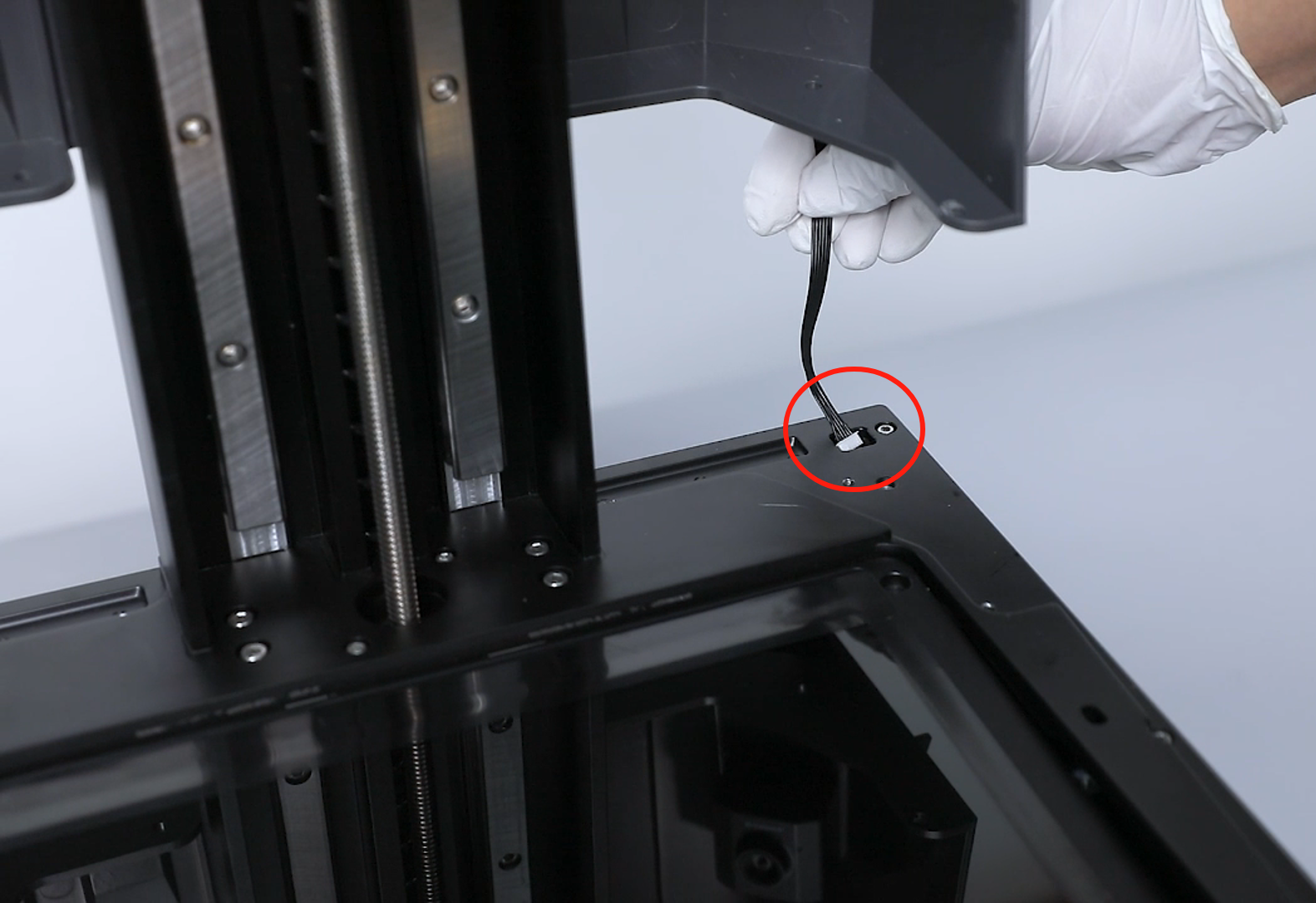
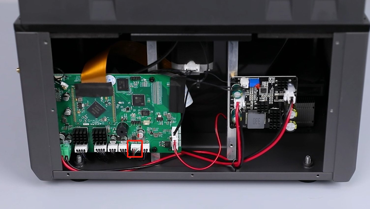
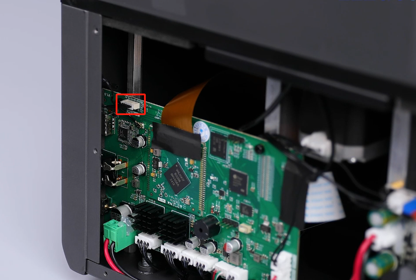
- Unplug the camera cables and the mechanical sensor cable on the motherboard.
- Remove the ribbon cables of the mechnical sensor from the back of the motherboard.
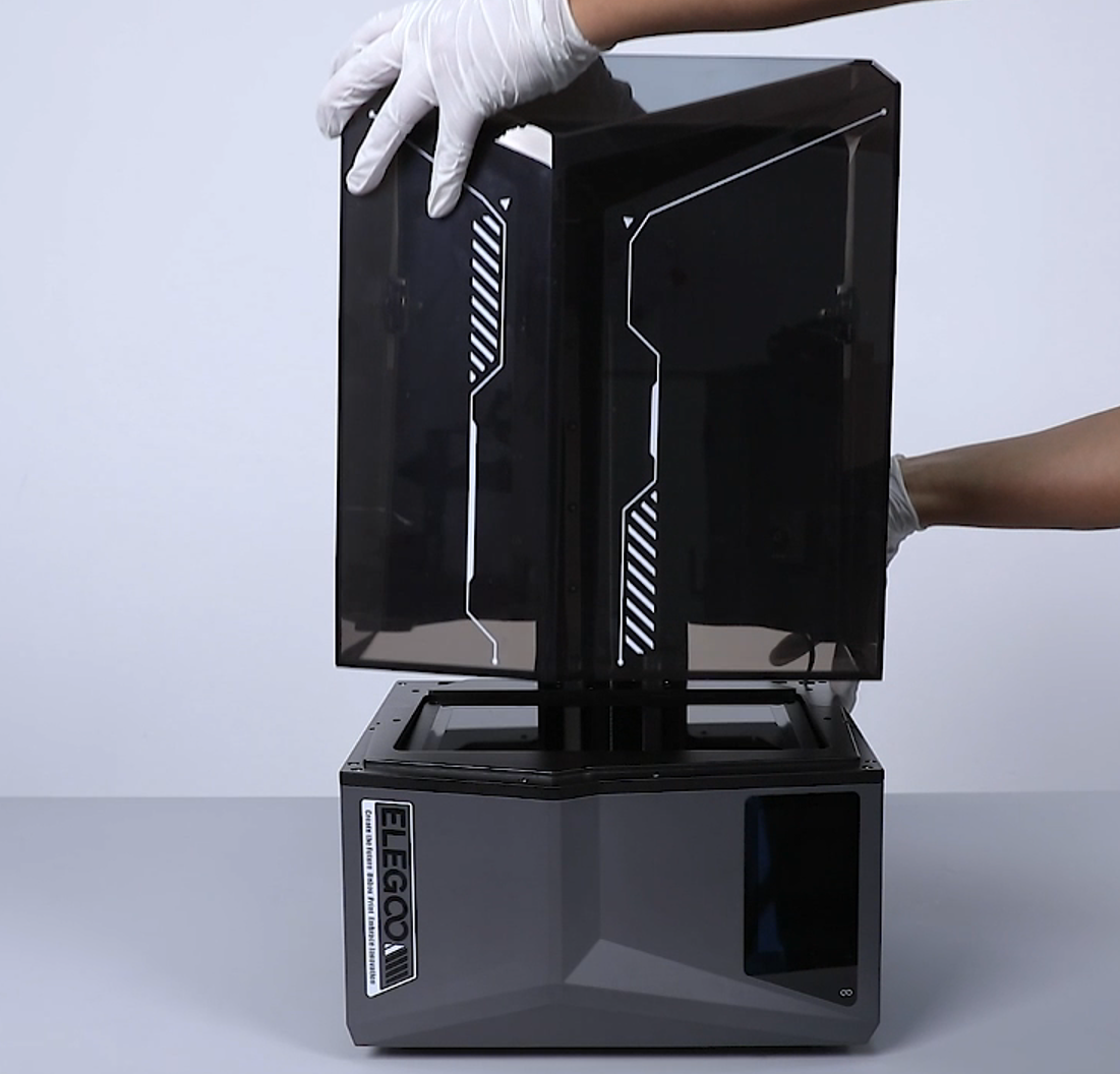
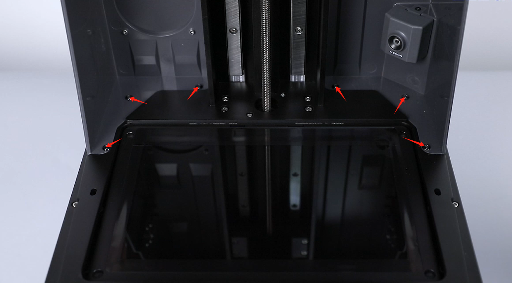
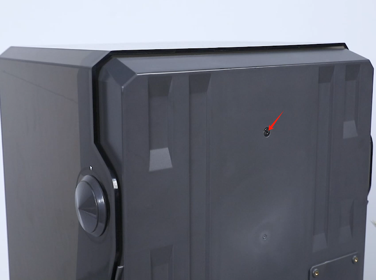
- Loosen the 6 screws fixed at the lower part of the top cover and the screw at the back side of the top cover using a 2.5 mm Allen key.


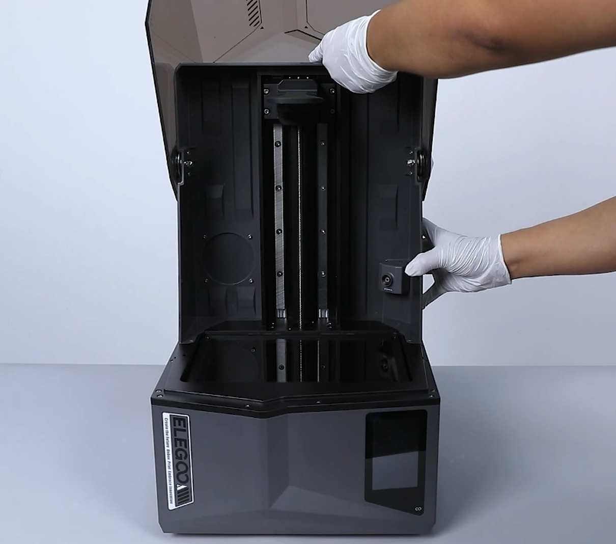
- Remove the top cover of the printer.
Note: Tidy up the ribbon cables of the camera in the reserved holes at the right side.
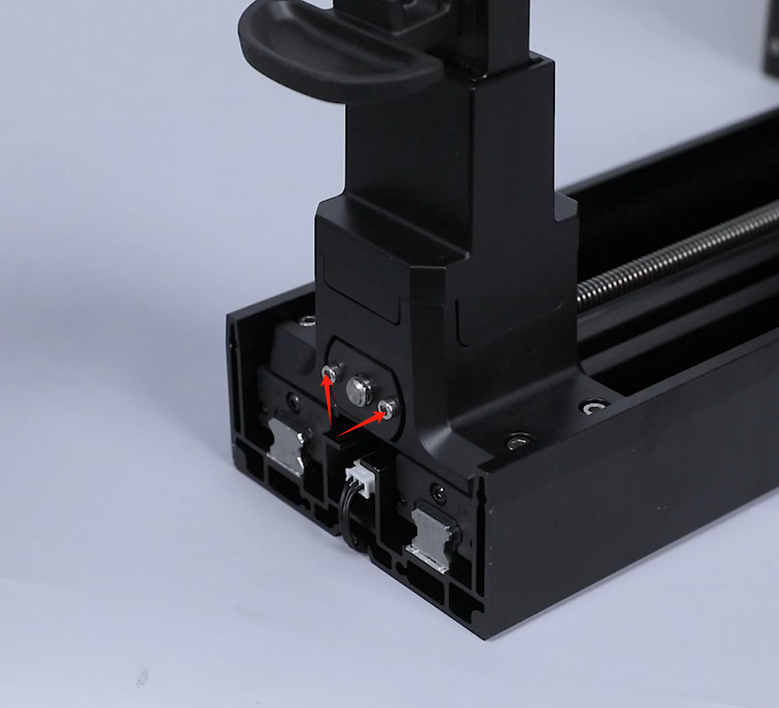
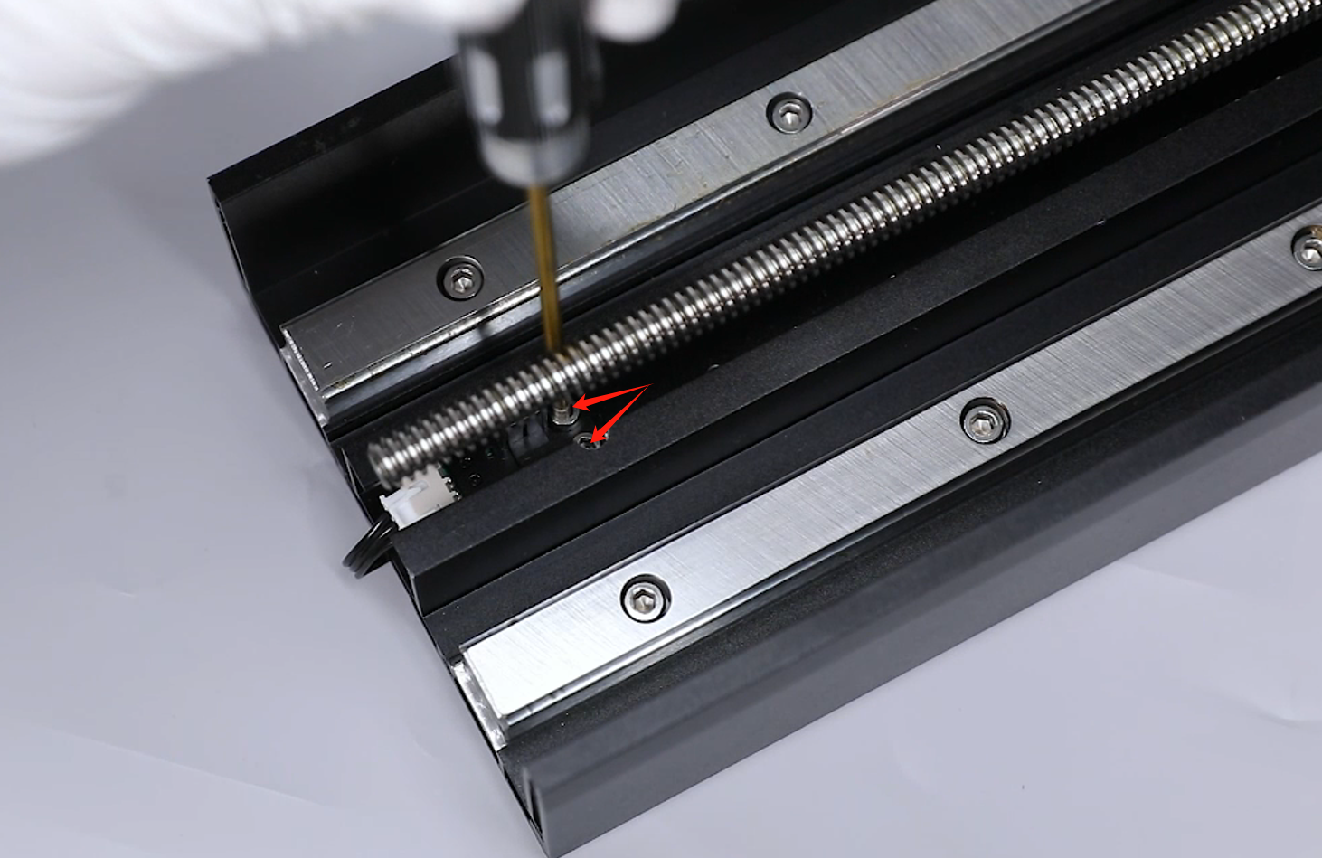
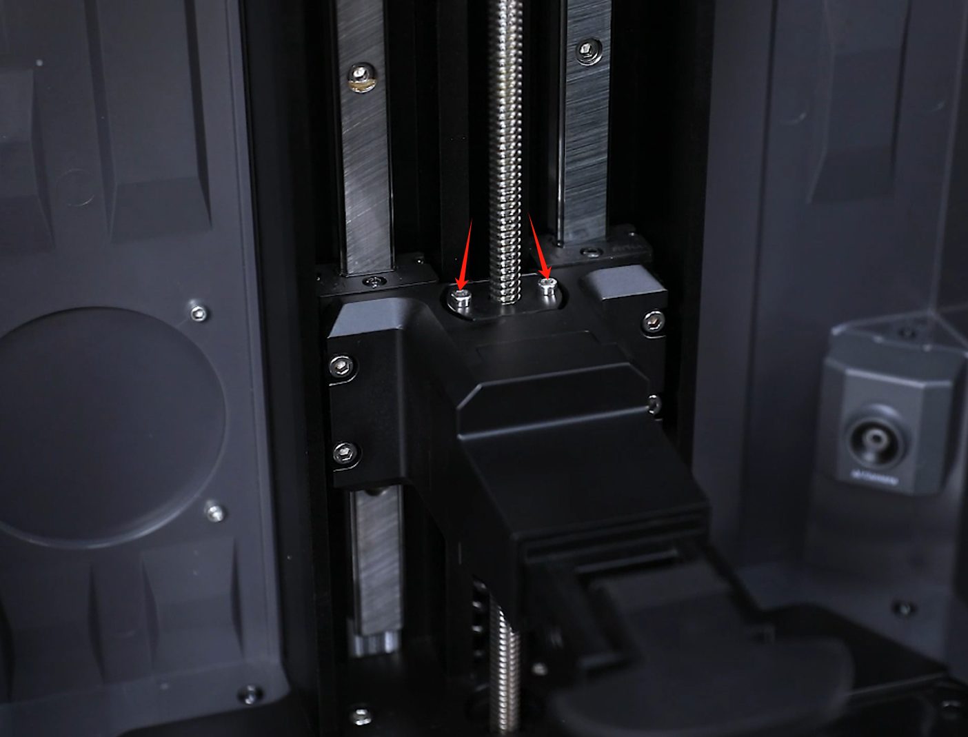
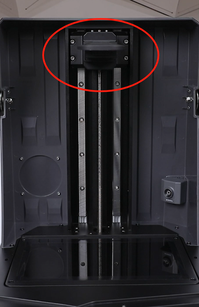
- Put the printer on its side. Loosen the 2 screws securing the nut using a 2.5 mm Allen key.
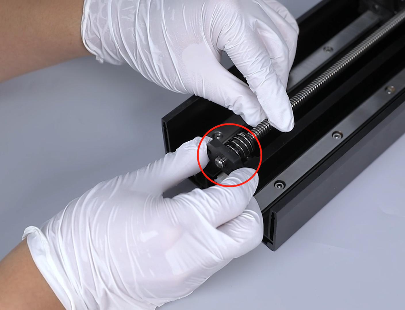
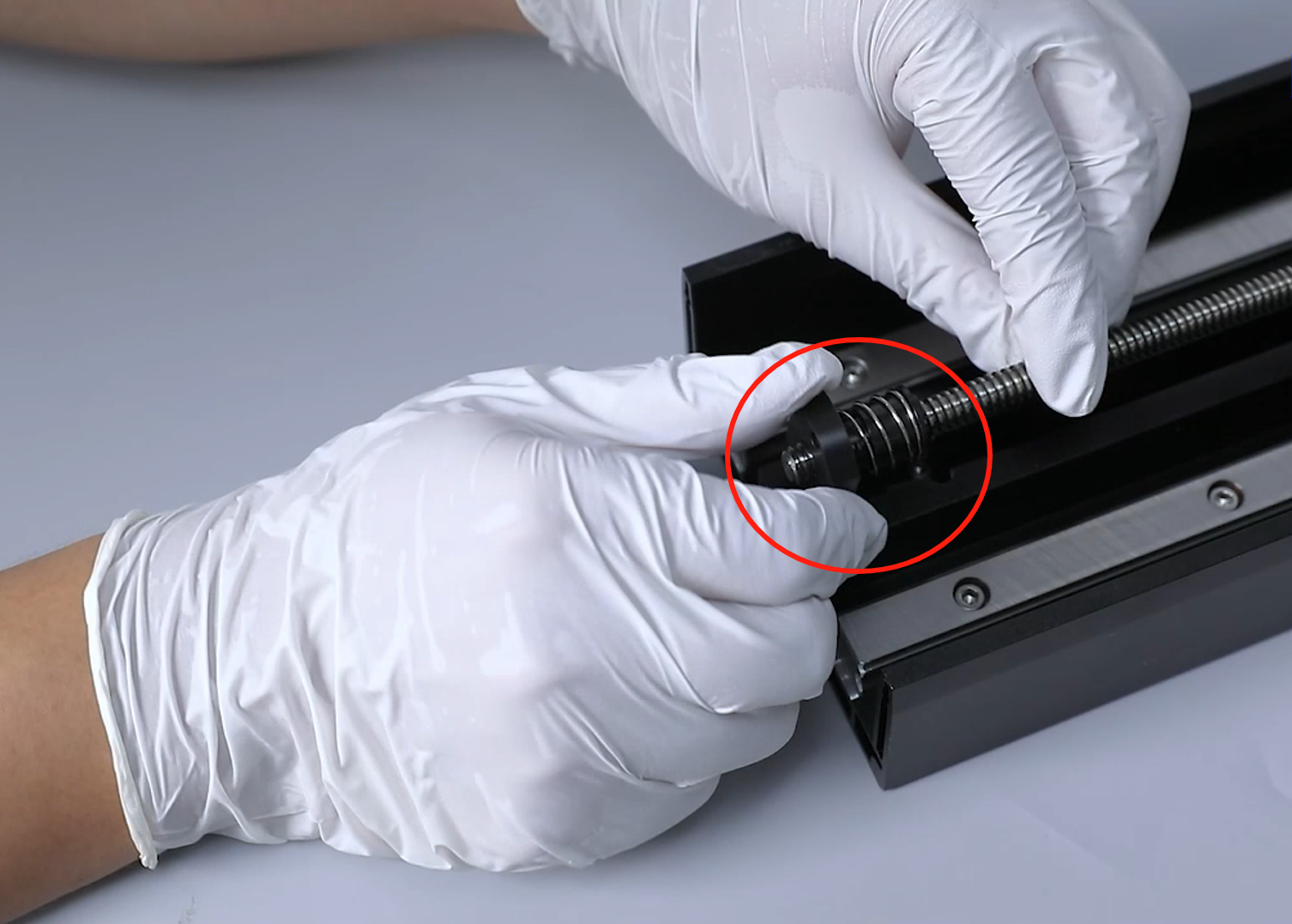
- Hold the lead screw with one hand and turn the nut with the other hand to remove it from the top of the lead screw.
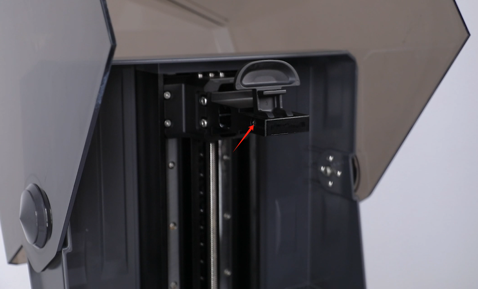
- Use a 2.5 mm Allen wrench to loosen the 2 screws securing the Z-axis limit switch.

- Remove the Z-axis limit switch from above the Z-axis. Unplug the ribbon cables of the Z-axis limit switch and remove the limit switch.
- Use a 3.0 mm Allen wrench to loosen the 4 screws securing the cantilever.
- Remove the Z-axis cantilever from above the printer's Z-axis.
CAUTION: Do not remove the slider out of the guide rail. The ball may fall off.
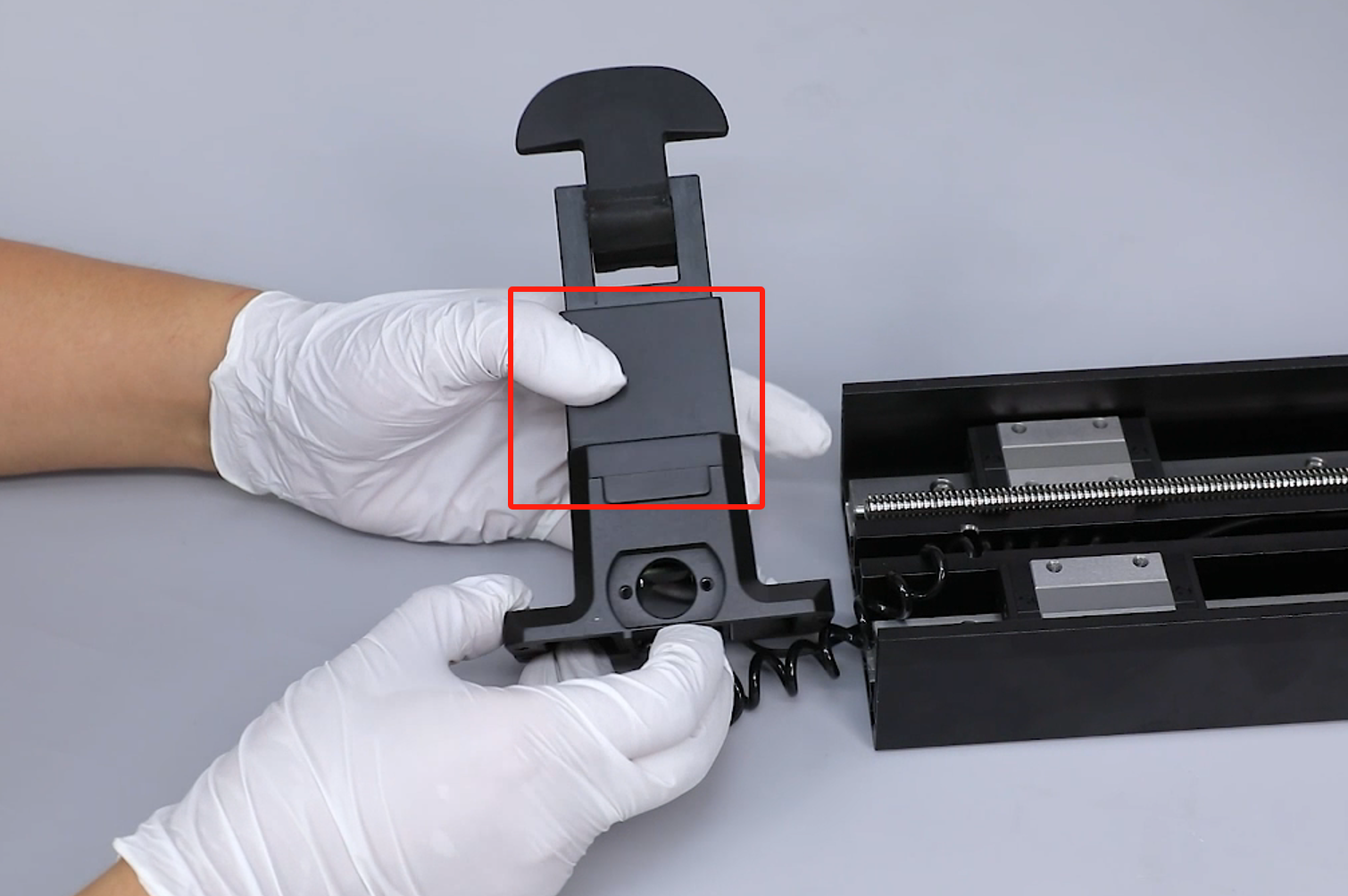
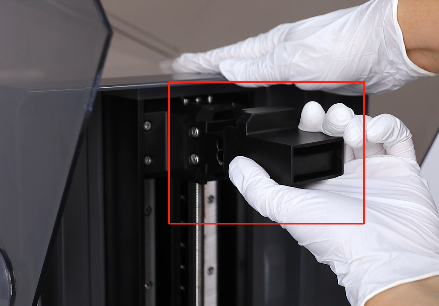
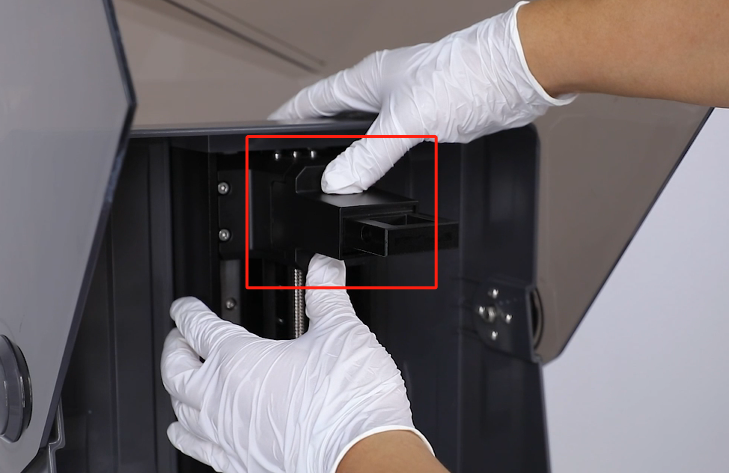
- Remove the protective cover by gently pulling outward.
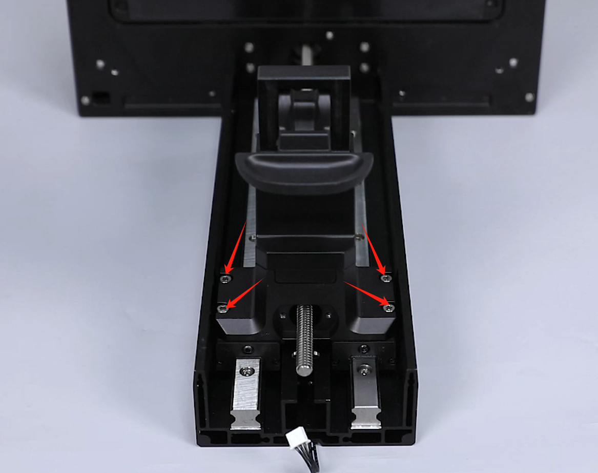
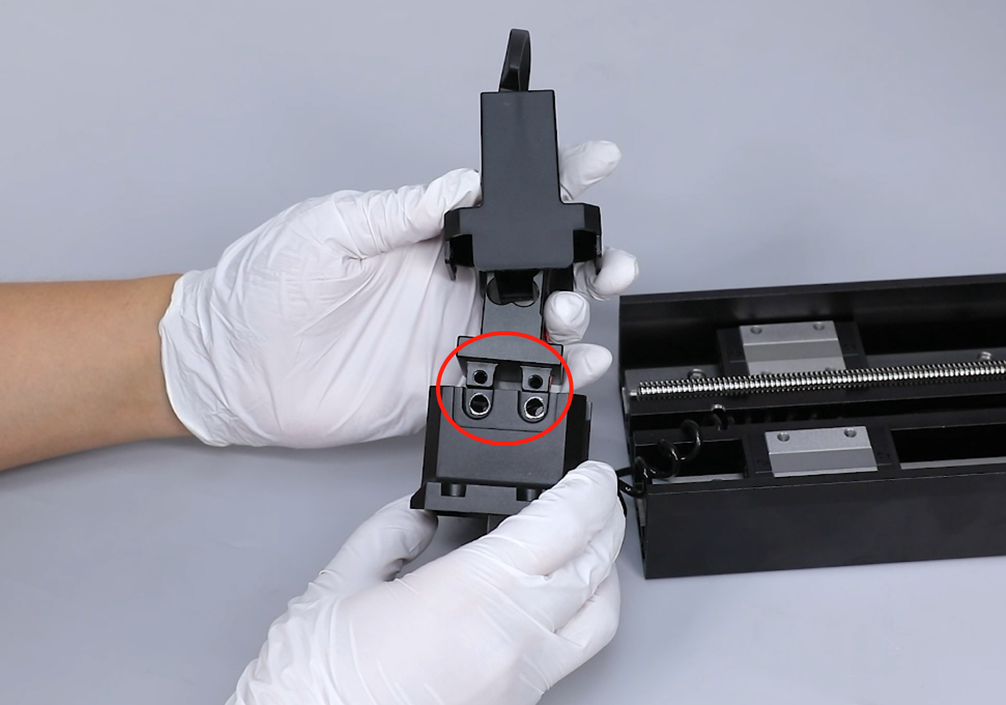
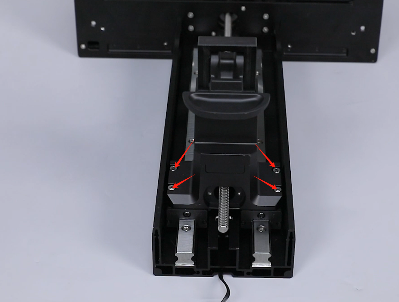
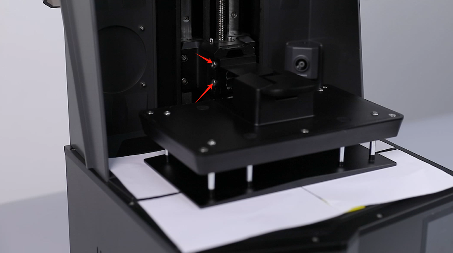
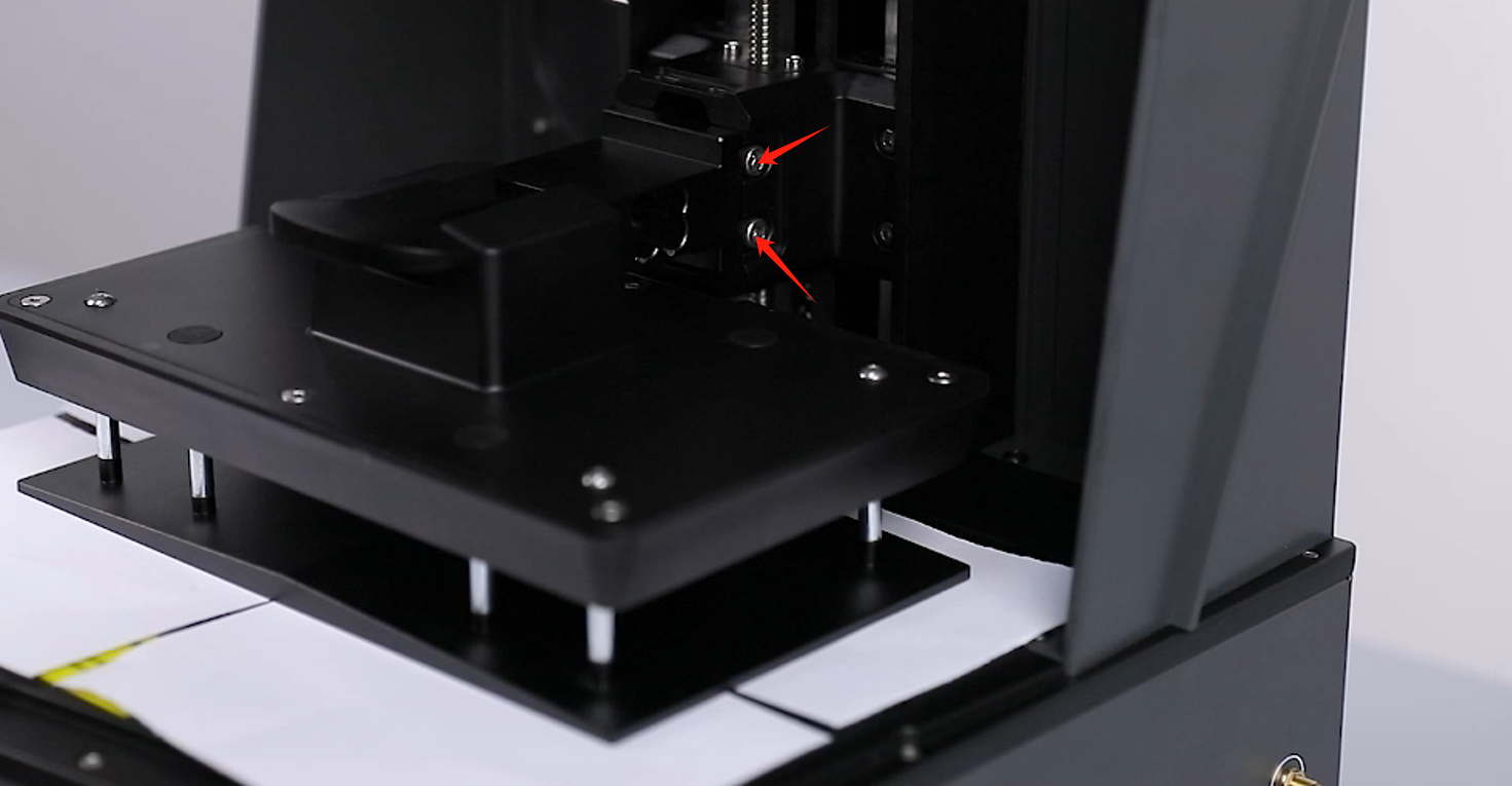
- Use a 4.0 mm Allen wrench to loosen the 4 screws securing the cantilever junction blocks.
Note: Use a hair dryer to make it easier to loosen the screws, where the adhesive is applied to the front.
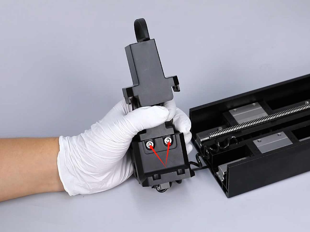
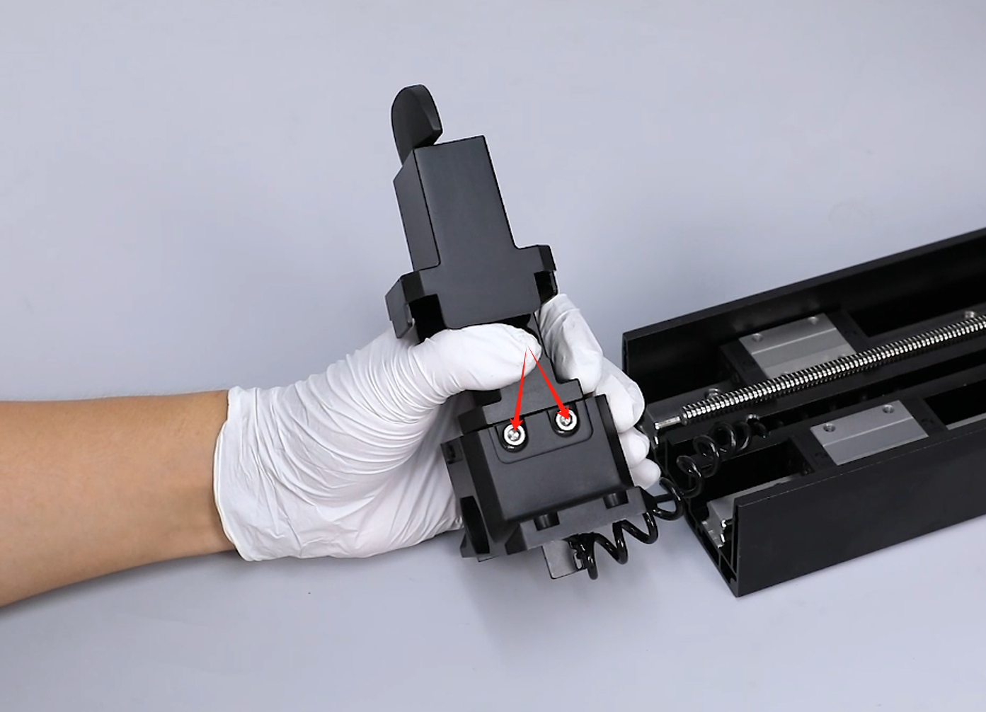
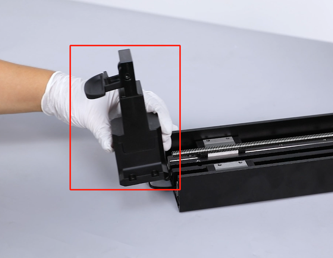
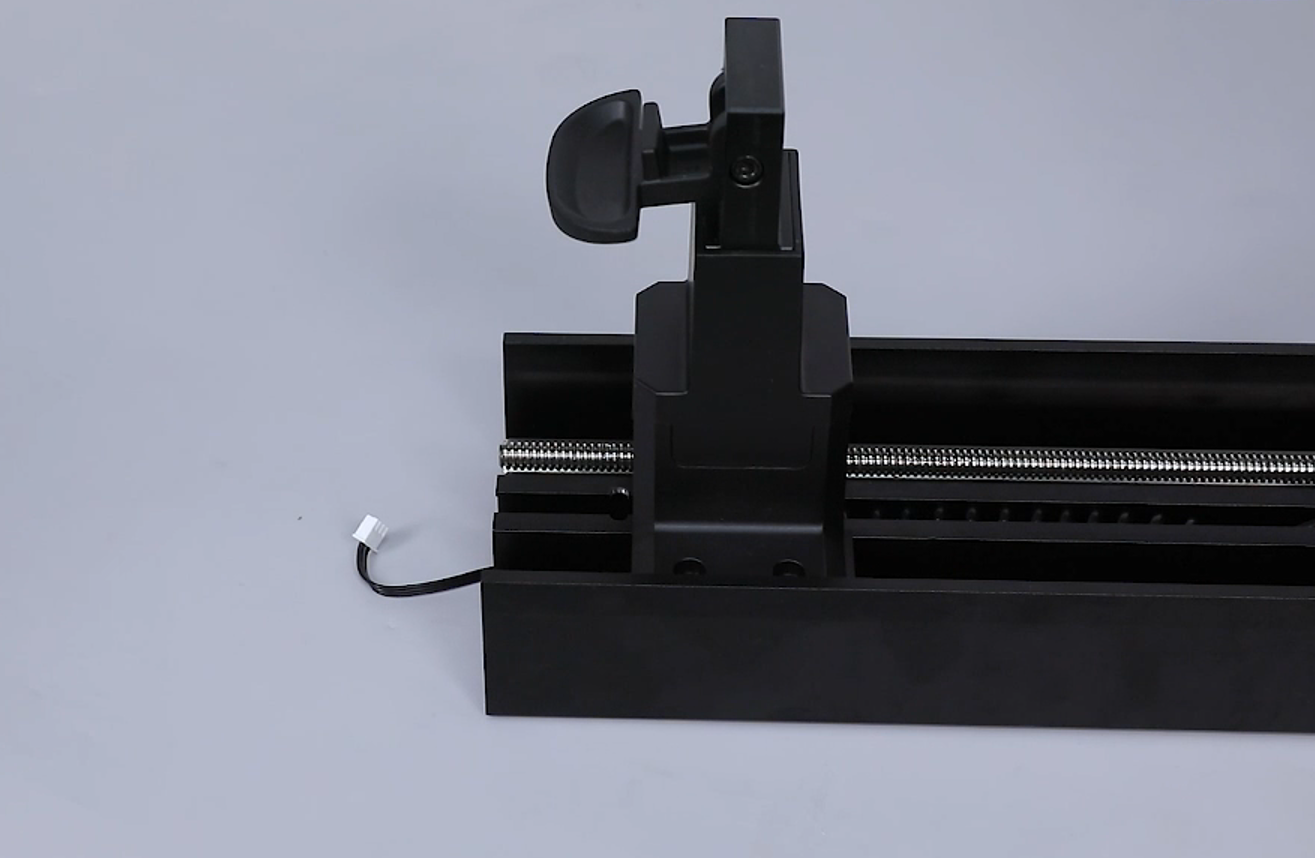
- Lift up the front cantilever beam to remove it.
Note: There are mechanical sensor cables. Handle with caution.

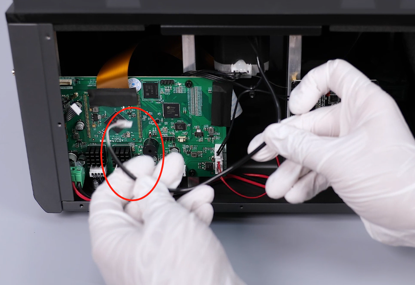
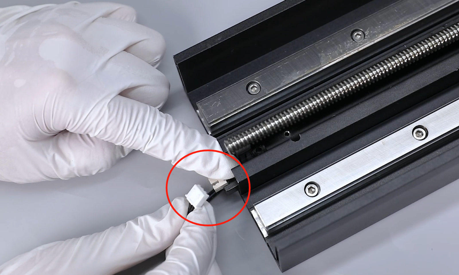
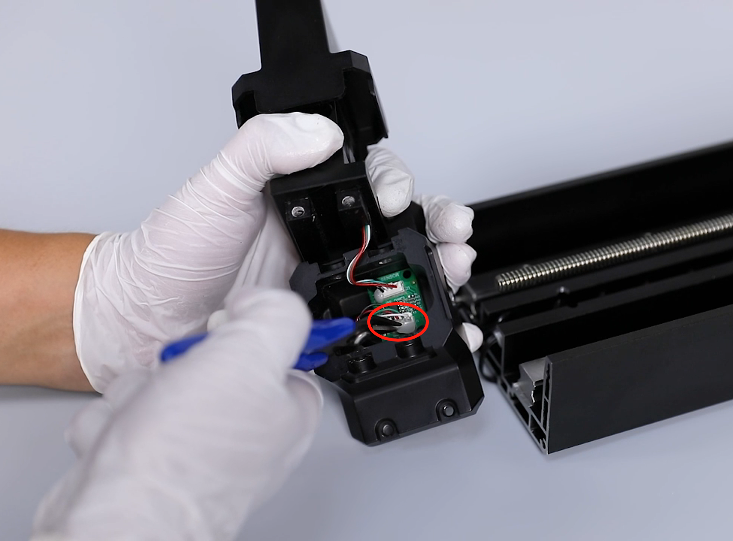
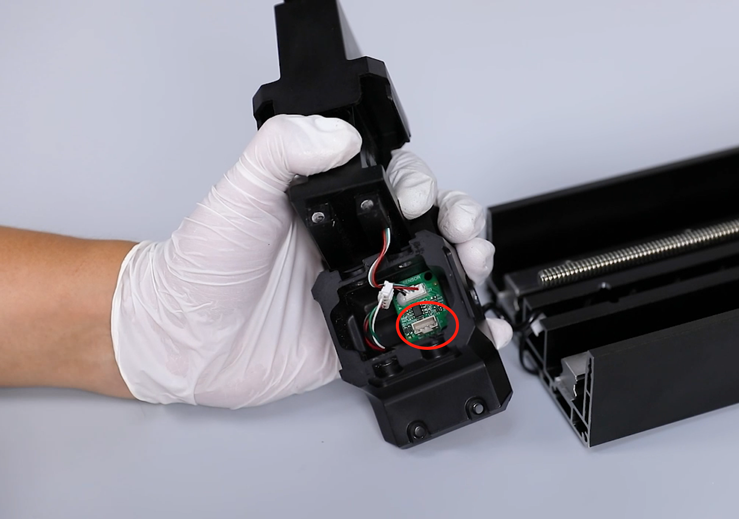
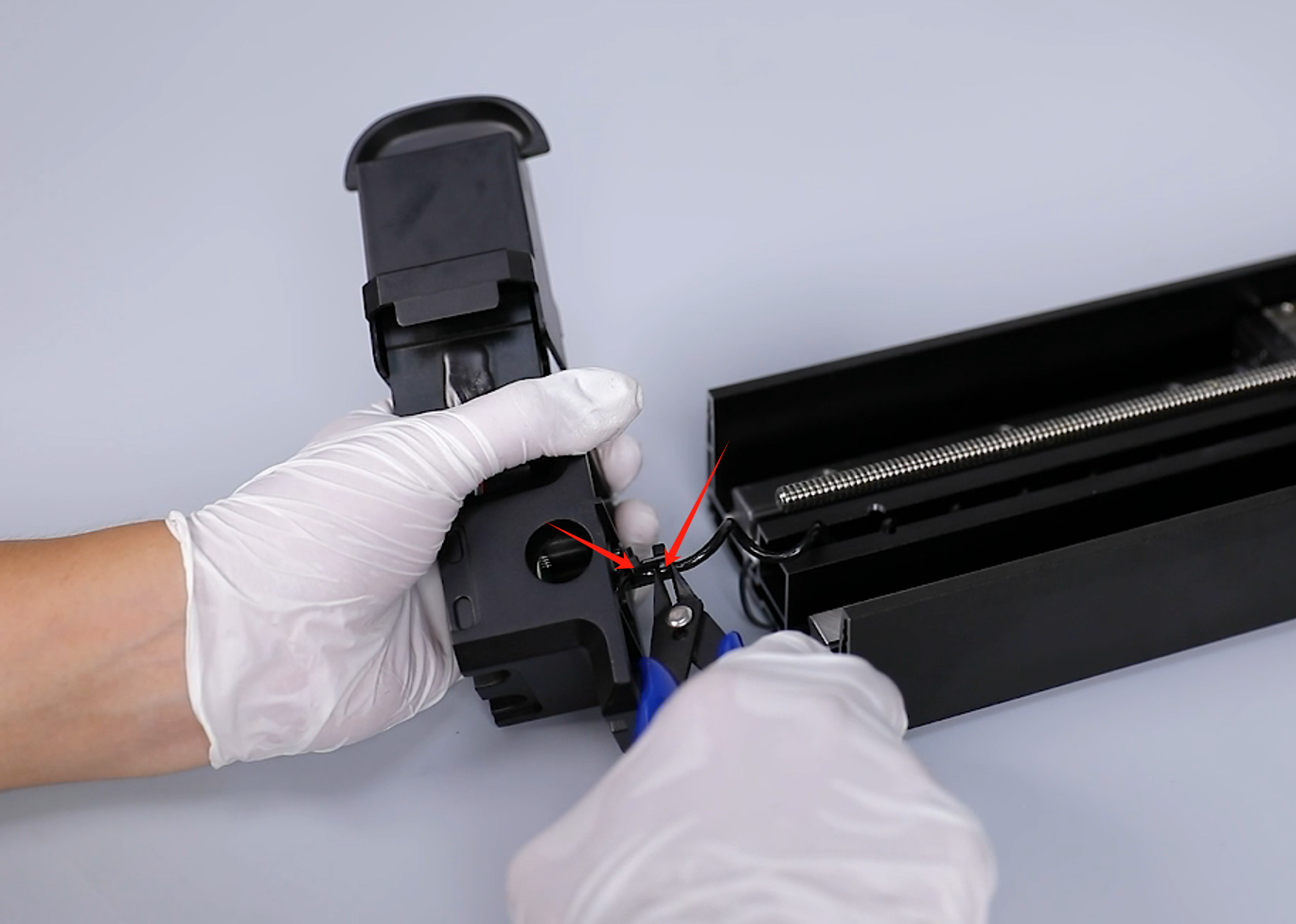
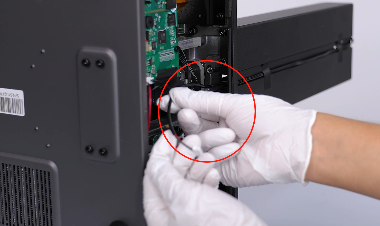
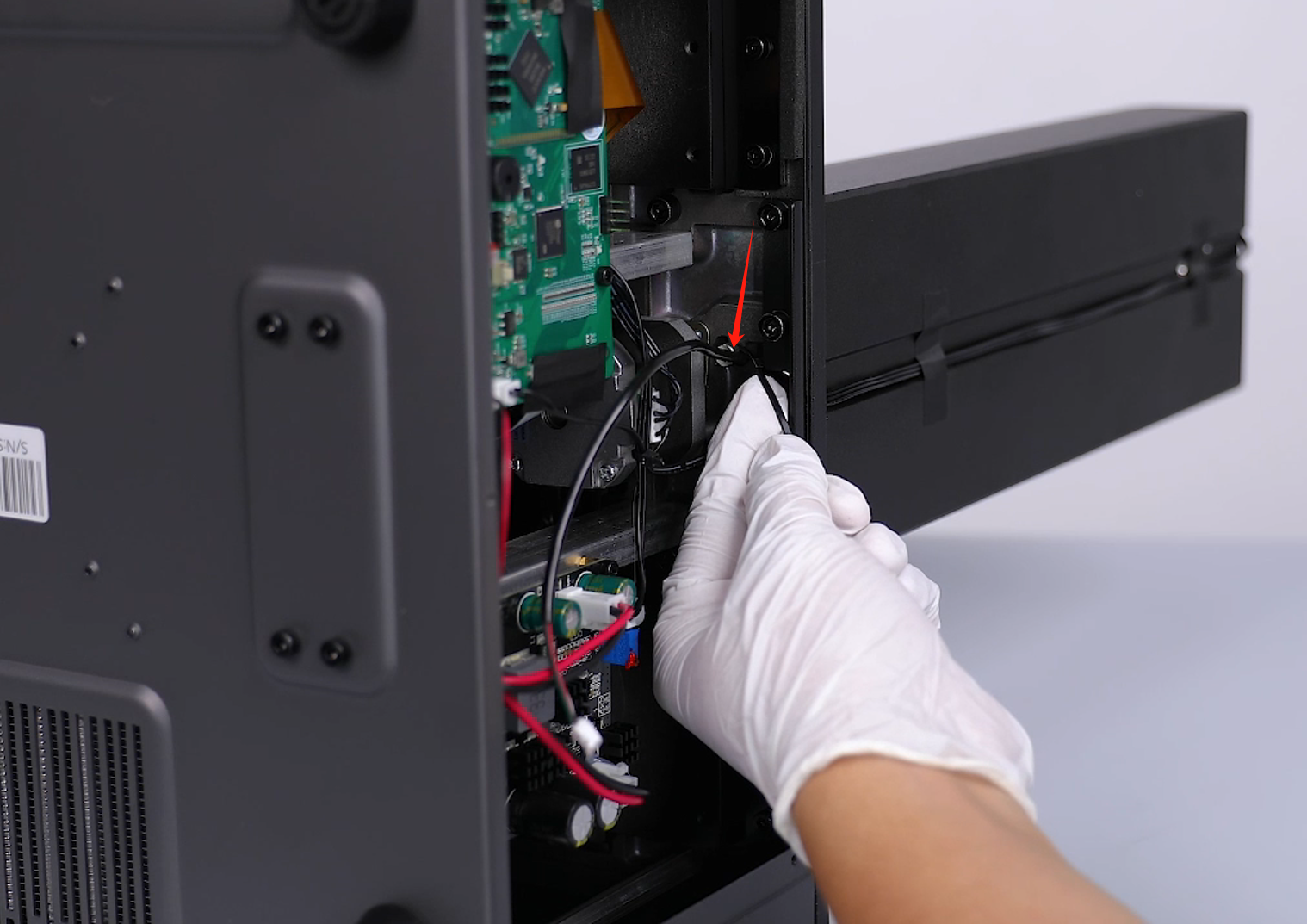
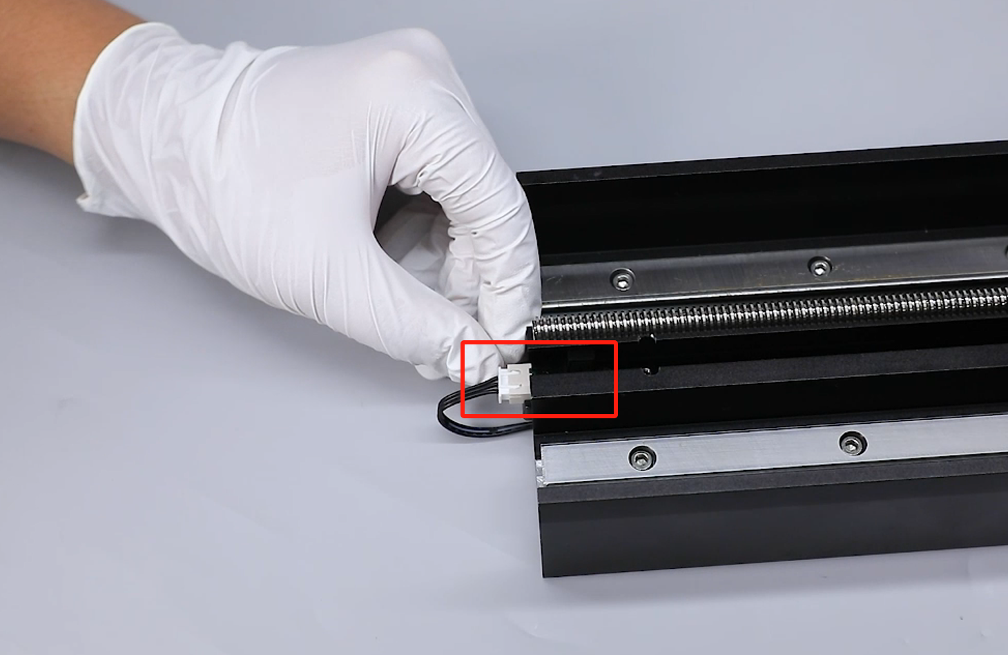
- Use a pair of diagonal pliers to cut the hot glue at the spring wire port, then unplug the spring wire port on the motherboard.
- Use diagonal pliers to cut the cable ties that hold the spring wire on the limit switch flap.
- Remove the spring wire from the reserved hole.
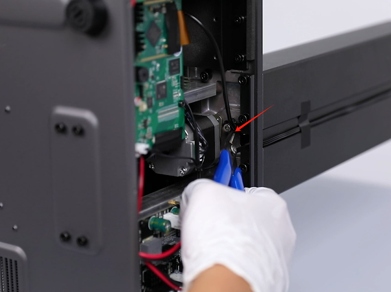
- Use a pair of diagonal pliers to cut off the cable ties securing the spring wire at the bottom of the printer.
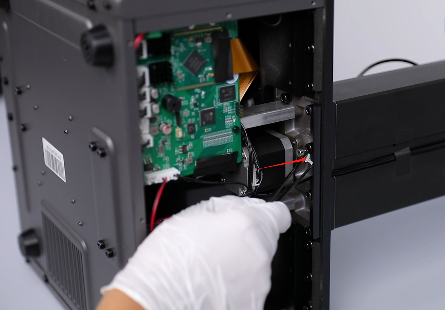
- From the bottom of the printer, organize the spring wire and thread it through the cable holes.
- Pull out the old spring wire above the Z-axis.
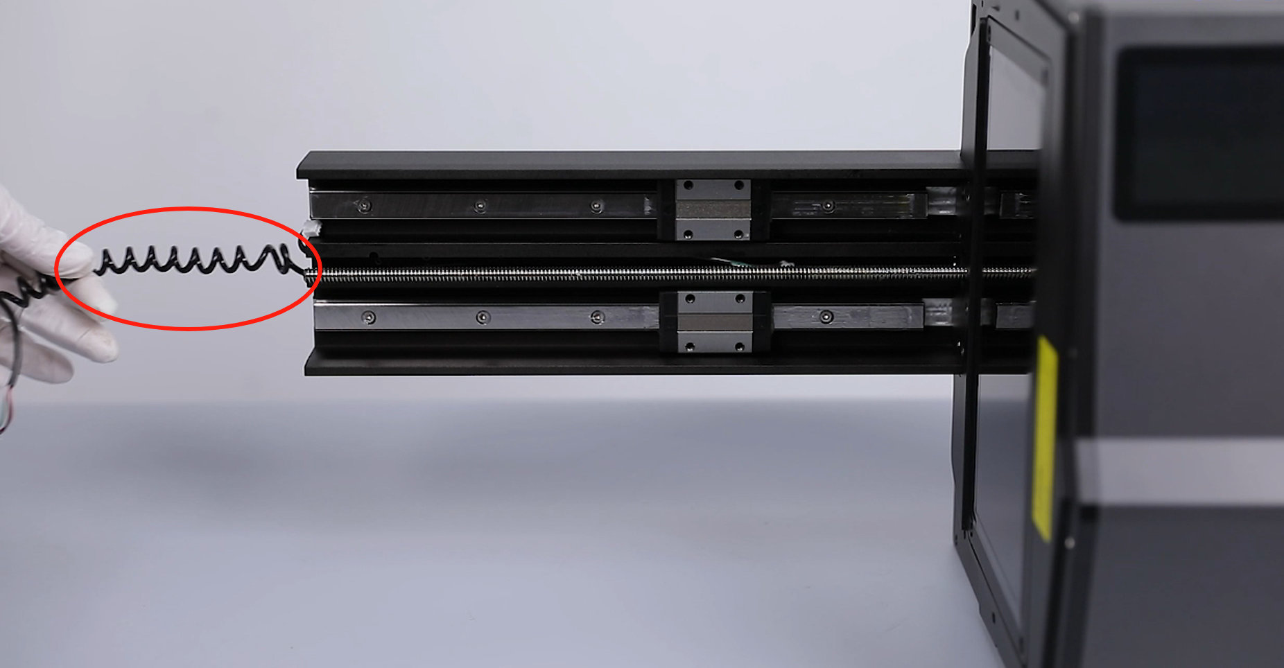
- Prepare the new spring wire. Insert the spring wire into the groove above the Z-axis. (The side with more straight cables is installed under the printer.)
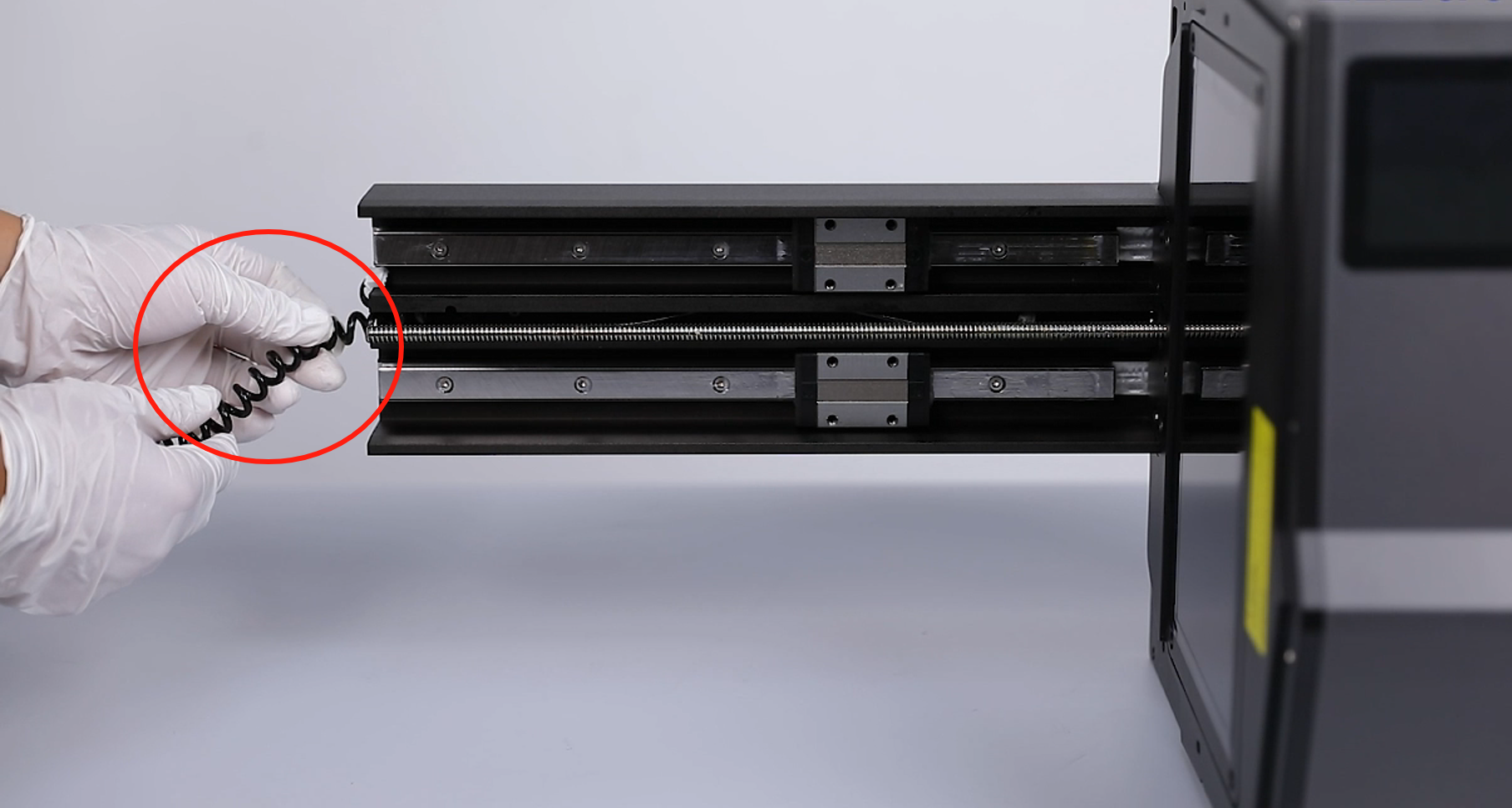
- Use a pair of tweezers to feed the spring wire port through the ribbon cable hole.
- Pull out the spring wire through the bottom of the printer. Secure the spring wire on the screw using cable ties.
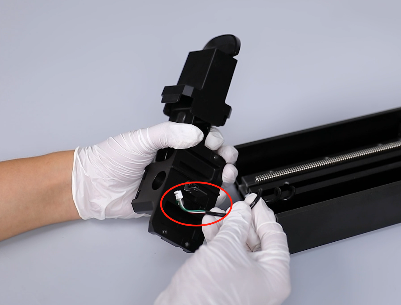
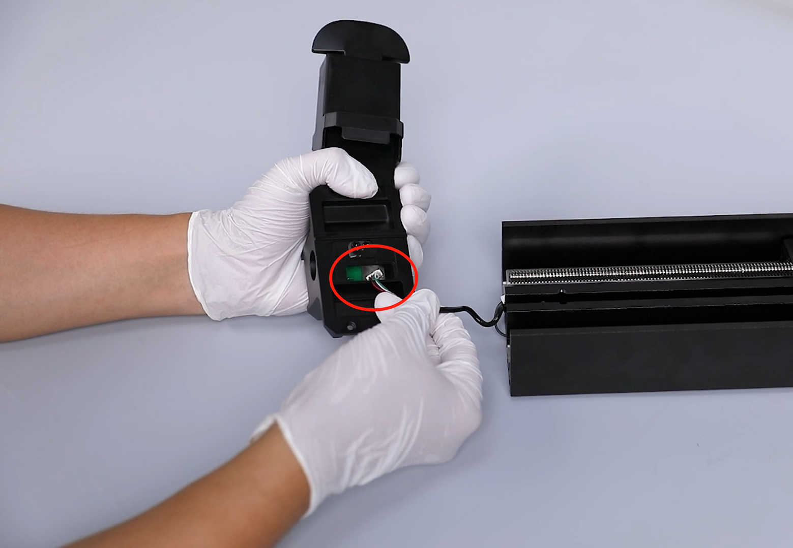
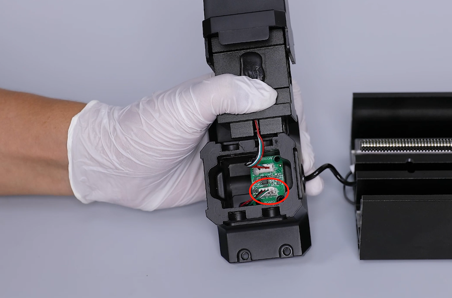
- Remove the cantilever. Thread the spring wire port through the reserved hole and insert it on the adapter board port.
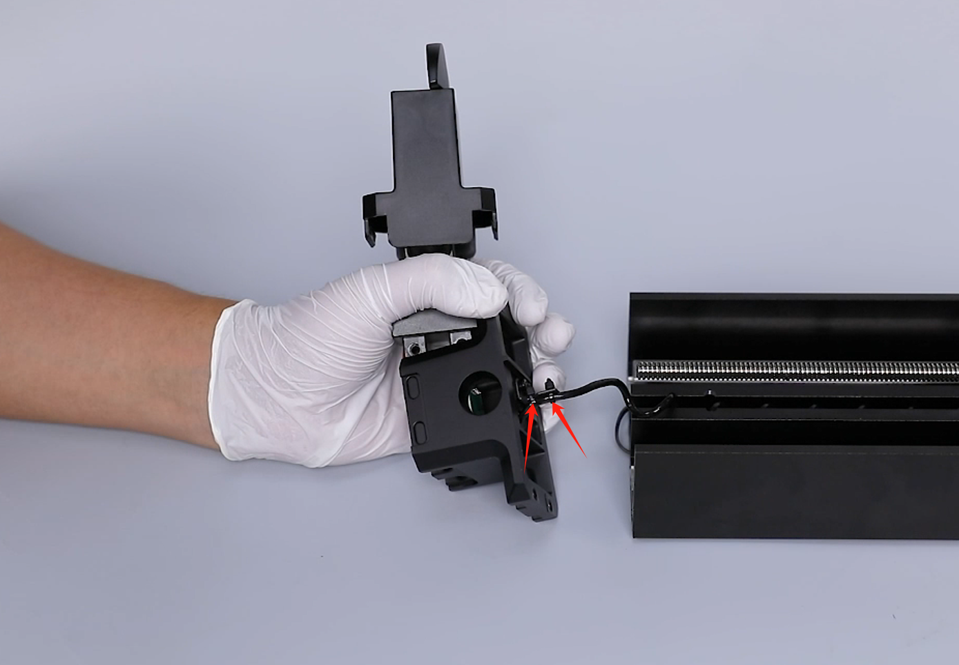
- Secure the spring wire to the limit switch stopper using cable ties.
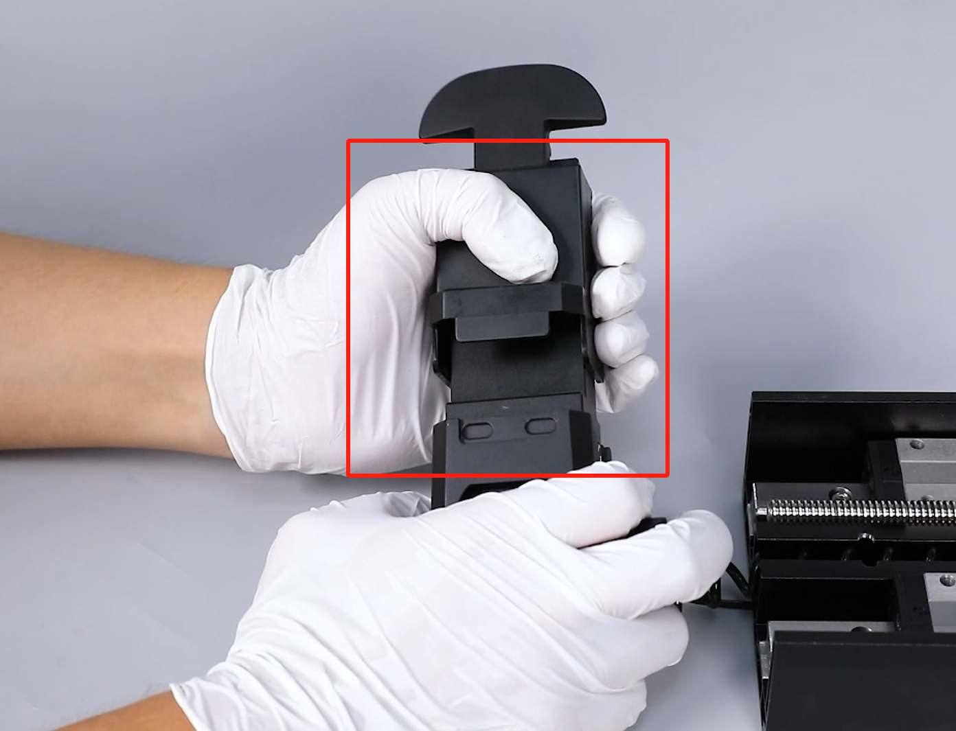
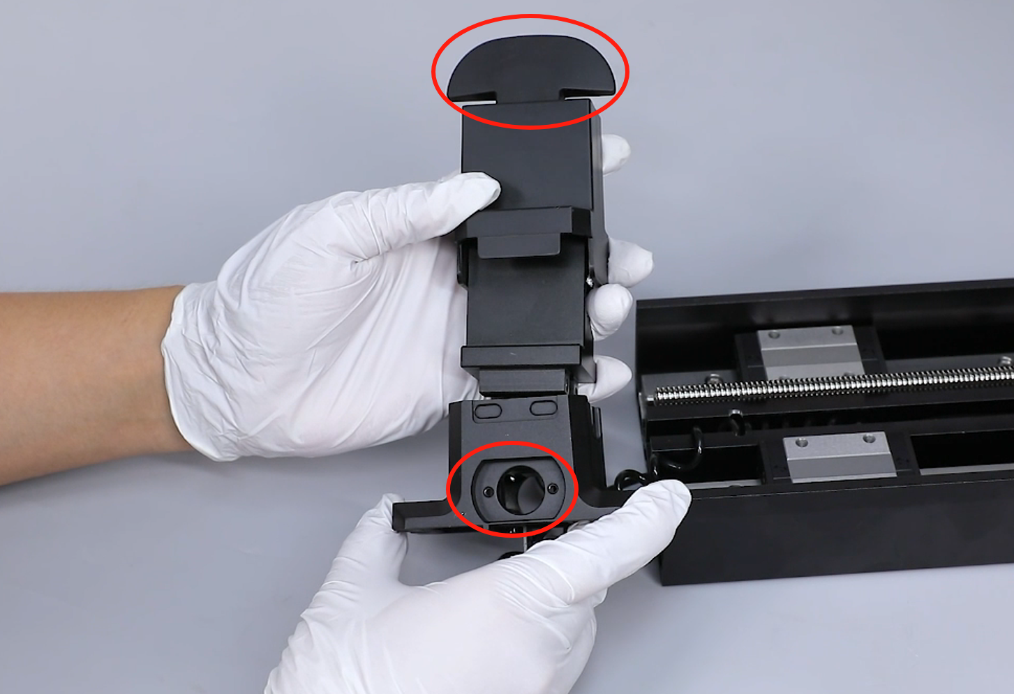
- Put the front cantilever beam in the installation position by aligning it the the screw holes, handle and zero-backlash nut.
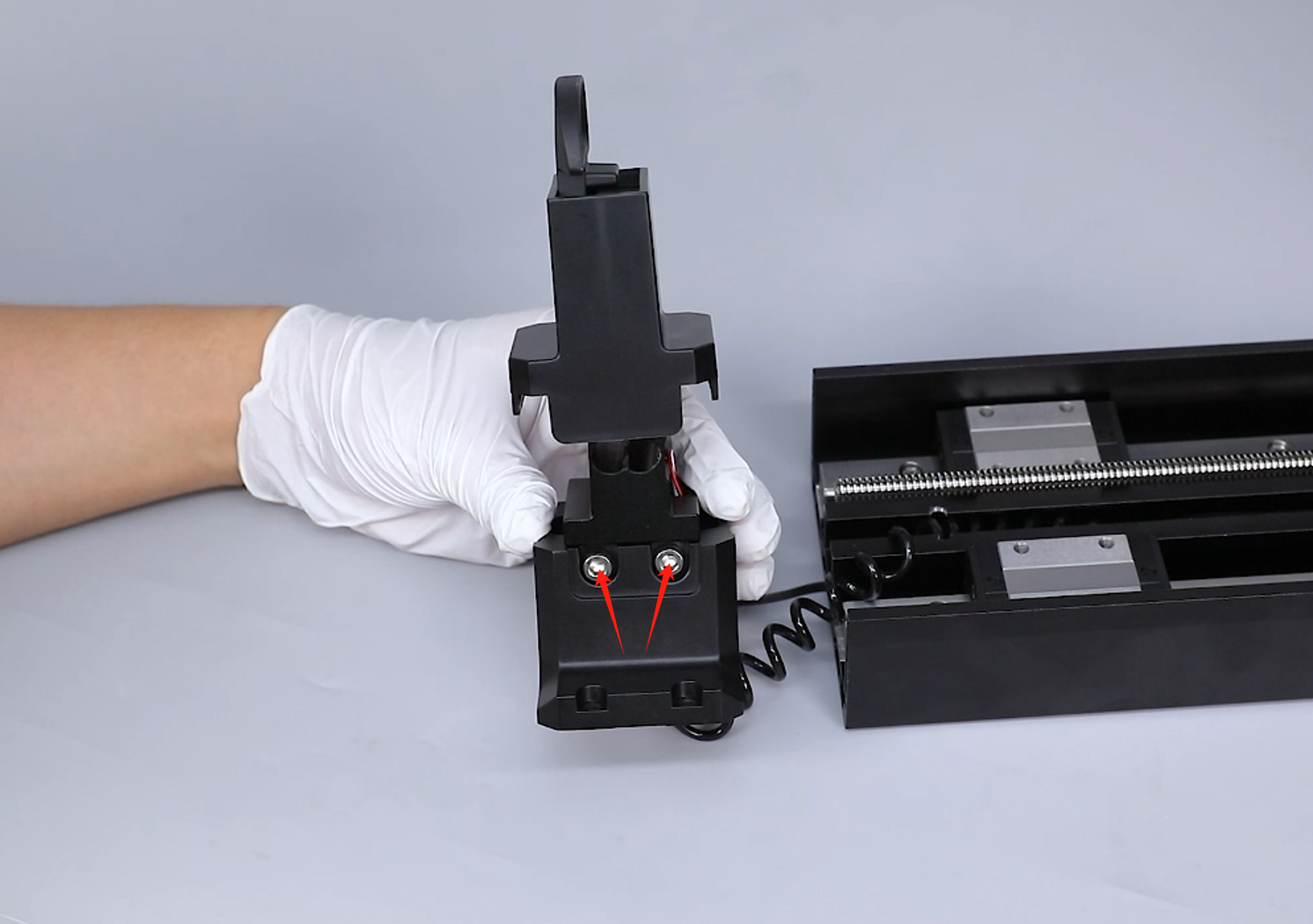
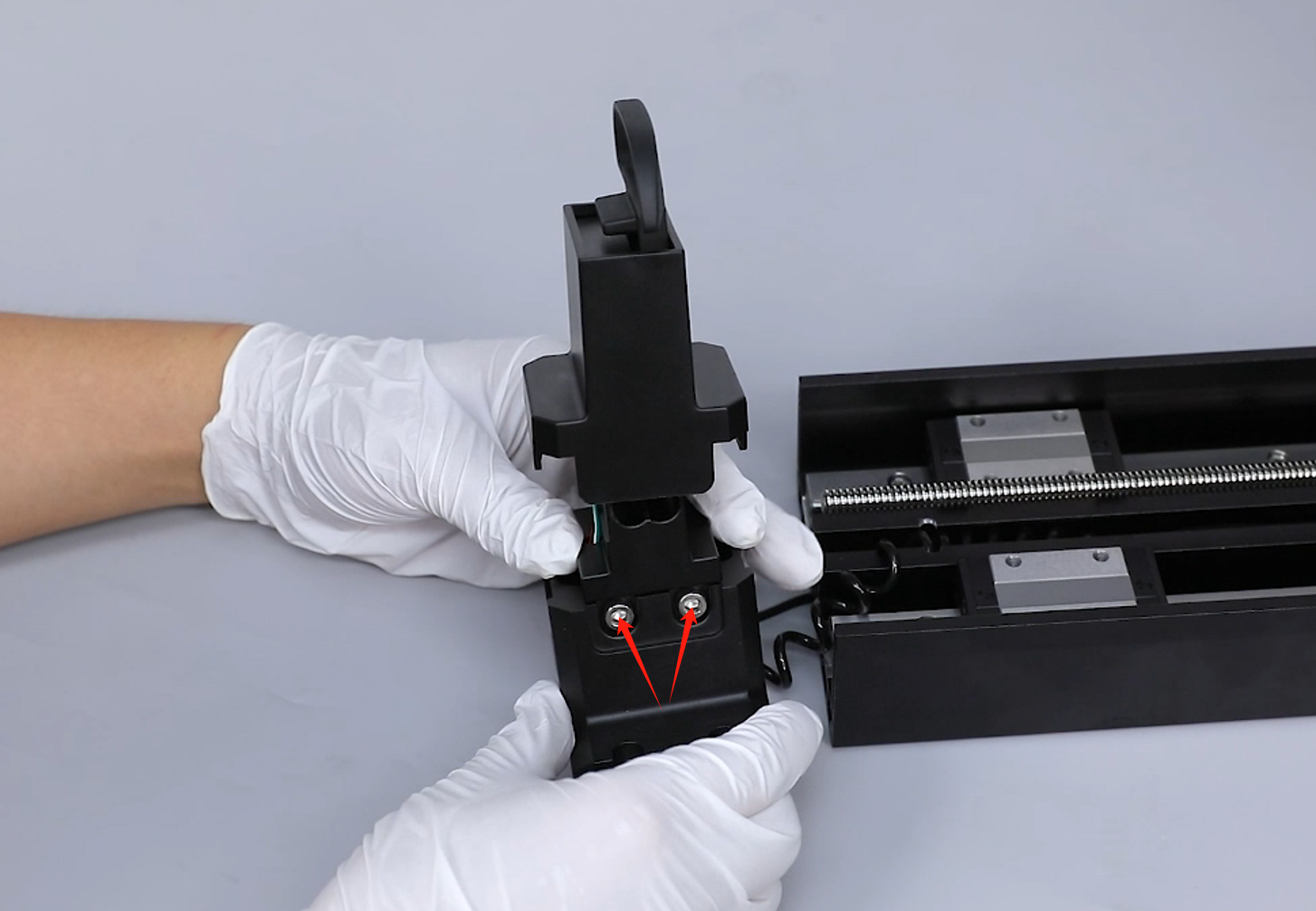
- Use a 4.0 mm Allen wrench to tighten the 4 screws securing the cantilever junction blocks by three-quarters of the required torque.
Note: Do not tighten the 4 screws completely until leveling the printer.
- Press the protective cover back into place.
- Pass the Z-axis cantilever through lead screw. Align the screw holes on the slider and put the Z-axis cantilever in the installation position.
- Secure 4 screws securing the cantilever by three-quarters depth using a 3.0 mm Allen key. After installing all screws, tighten the screws completely.
- Prepare the Z-axis limit switch. Put it in the groove at the top of the Z-axis installation position. Insert the ribbon cables of the Z-axis limit switch.
- Put Z-axis limit switch in the installation position by aligning it with the screw holes. Use a 2.5 mm Allen key to tighten the 2 screws securing the Z-axis limit switch.
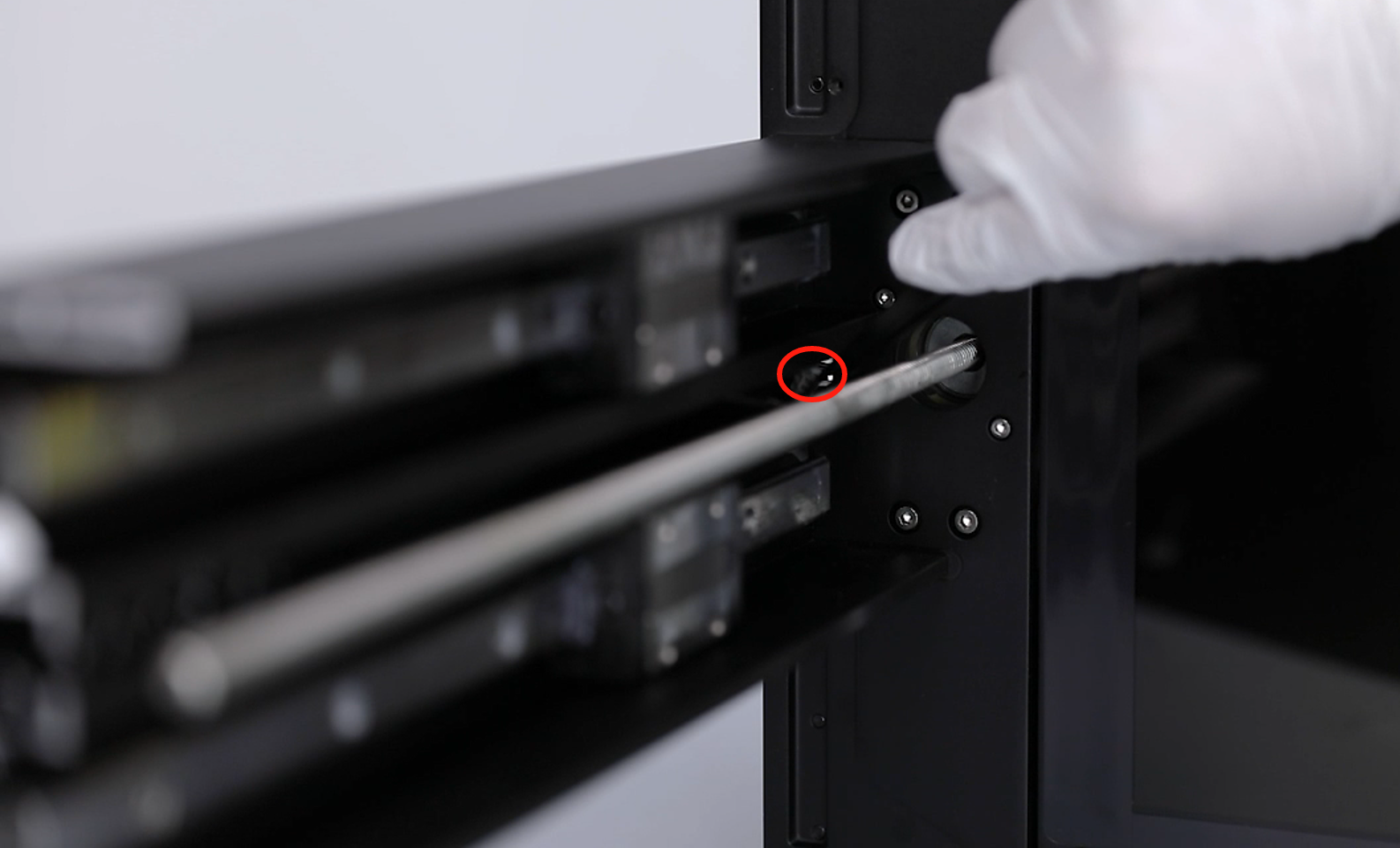
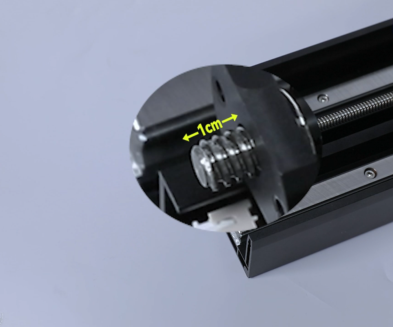
- Remove the nut. Hold the lead screw with one hand and turn the nut with the other hand to remove it from the top of the lead screw.
Note: Screw the nut to about 1 cm from the top of the lead screw.
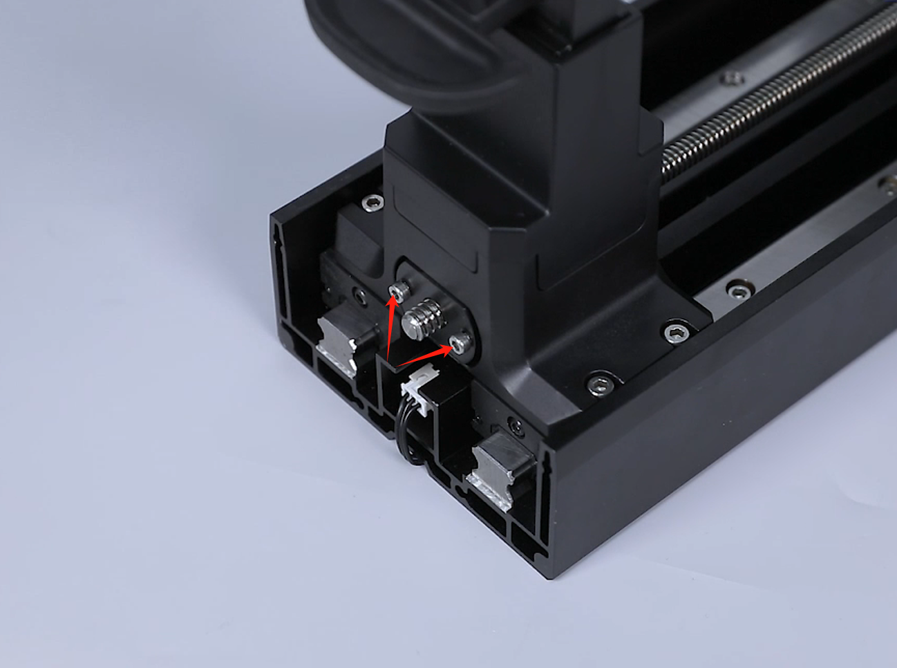
- Push the cantilever to align with the screw holes of the lead screw nut. Use an 3.0 mm Allen wrench to screw 2 securing screws by three quarters of the depth.
Note: The 2 screws should be tighten completely subsequently.
- Prepare the top cover of the printer. Put the top cover in the installation position by aligning it the the screw holes.
Note: Tidy up the ribbon cables of the camera in the reserved holes at the right side.
- Tighten the 6 screws fixed at the lower part of the top cover and the screw at the back side of the top cover using a 2.5 mm Allen key.
- Organize the mechnical sensor cables. Insert the camera cables and mechnical sensor cables into the motherboard port.
- Prepare the back cover of the printer. Use a 2.0 mm Allen wrench to tighten the 7 screws securing the back cover of the printer.
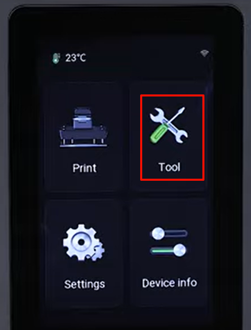
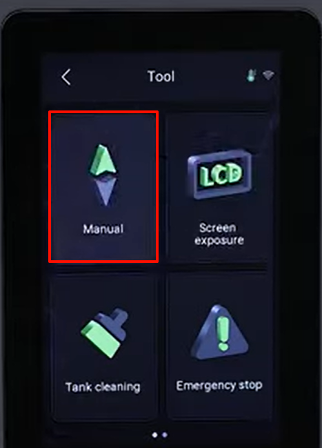
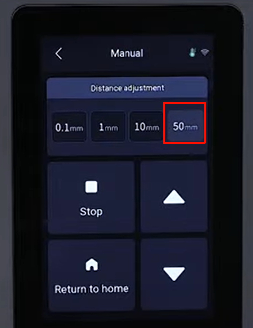
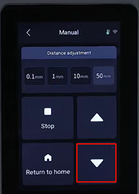
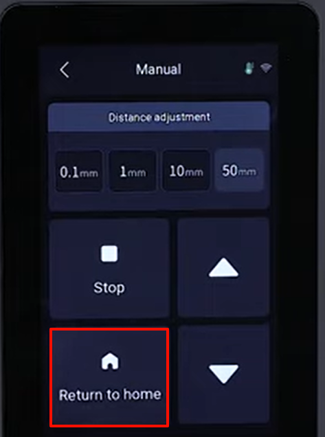
- Power on the printer. Tap "Tools - Manual - 50 mm" to lower the Z-axis.
- After the Z-axis lowered to the bottom position, use a 2.5 mm Allen key to securely tighten the 2 screws holding the nut multiple times.
- On the touchscreen, select "Home" and the printer starts its homing process.
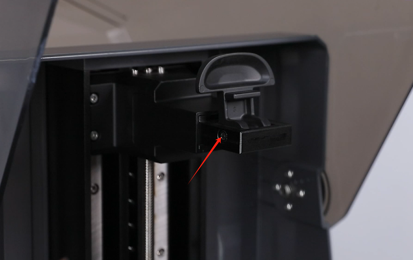
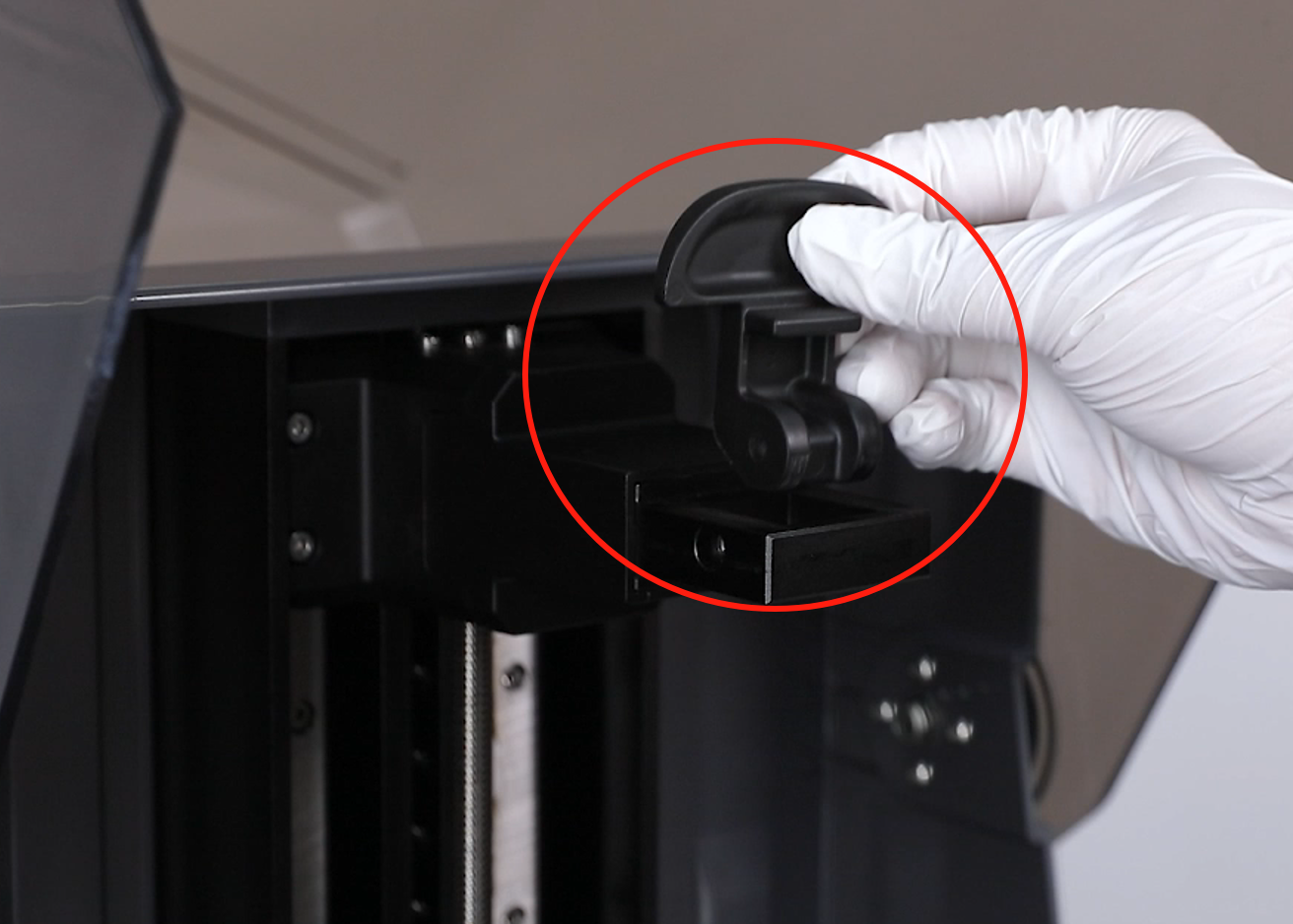
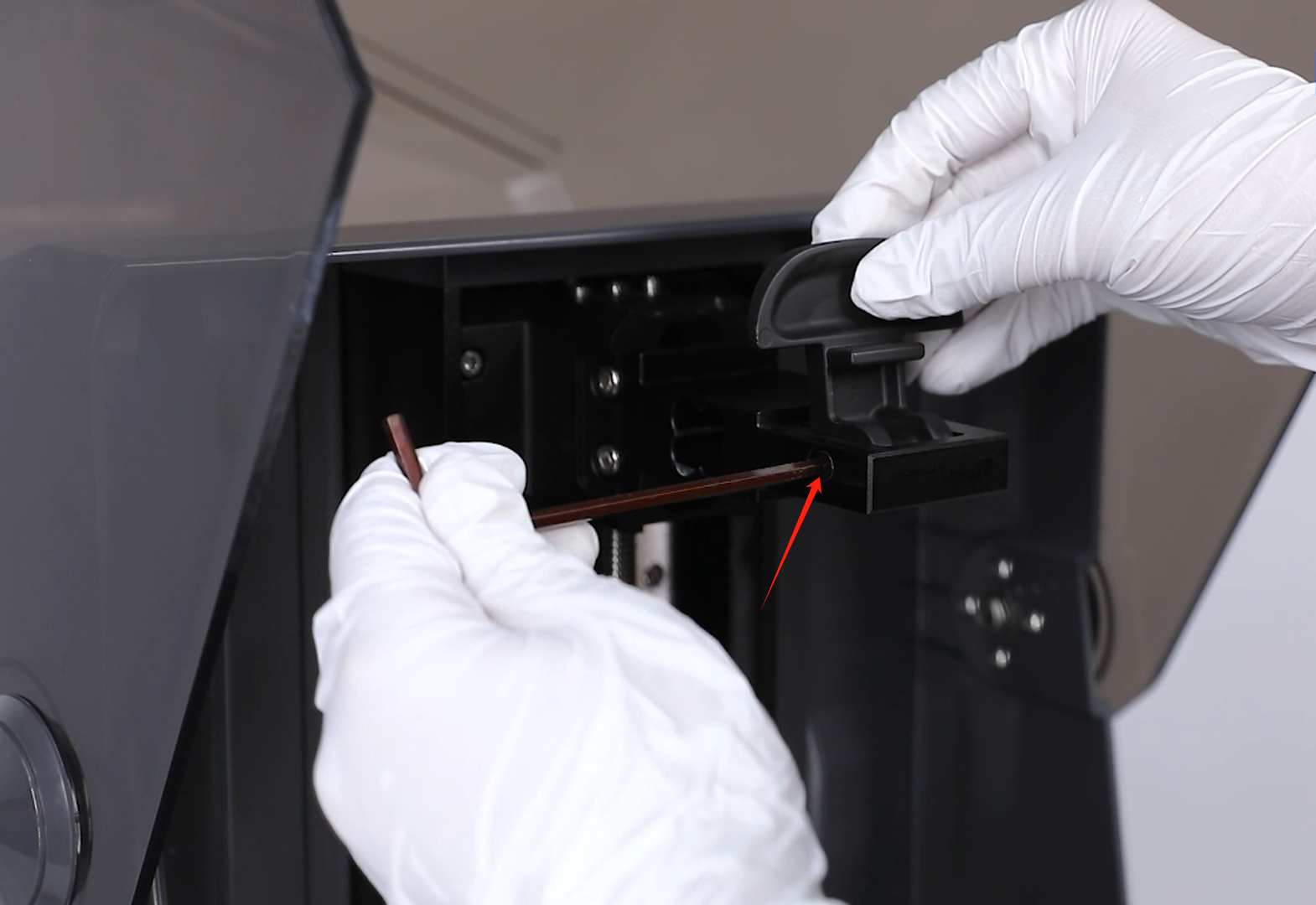
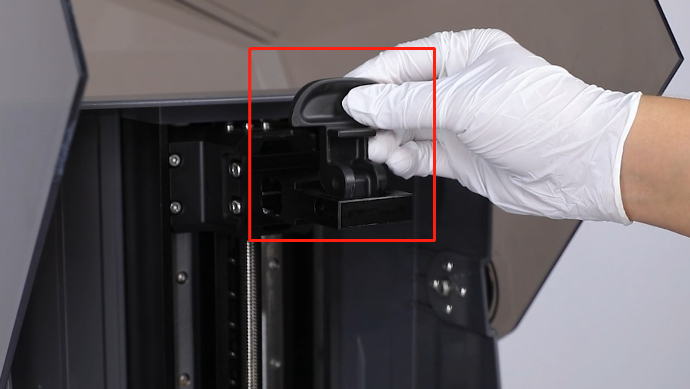
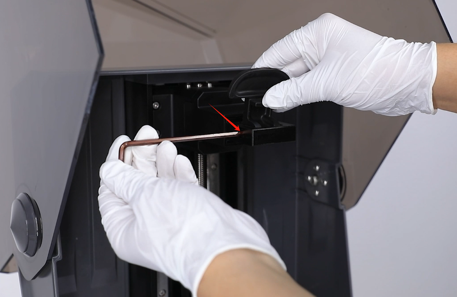
- Use a 4.0 mm Allen key to loosen the screw securing handle. then remove the handle. When the screw is about to come loose, hold the handle with your other hand to prevent it from falling.
- Remove the protective cover by gently pulling outward.
- Prepare the handle. Put it in the installation position by aligning it with the screw holes. Use a 4.0 mm Allen key to tighten the screw securing the handle.
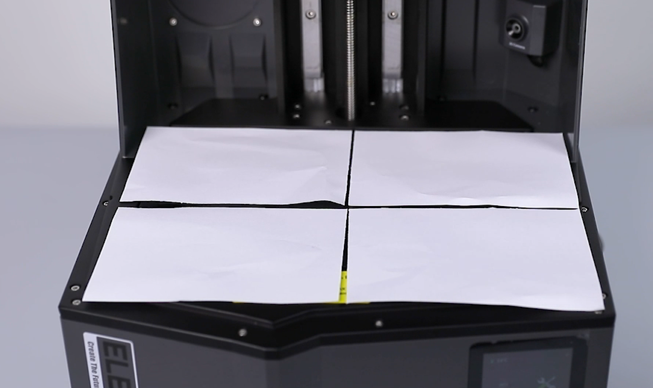
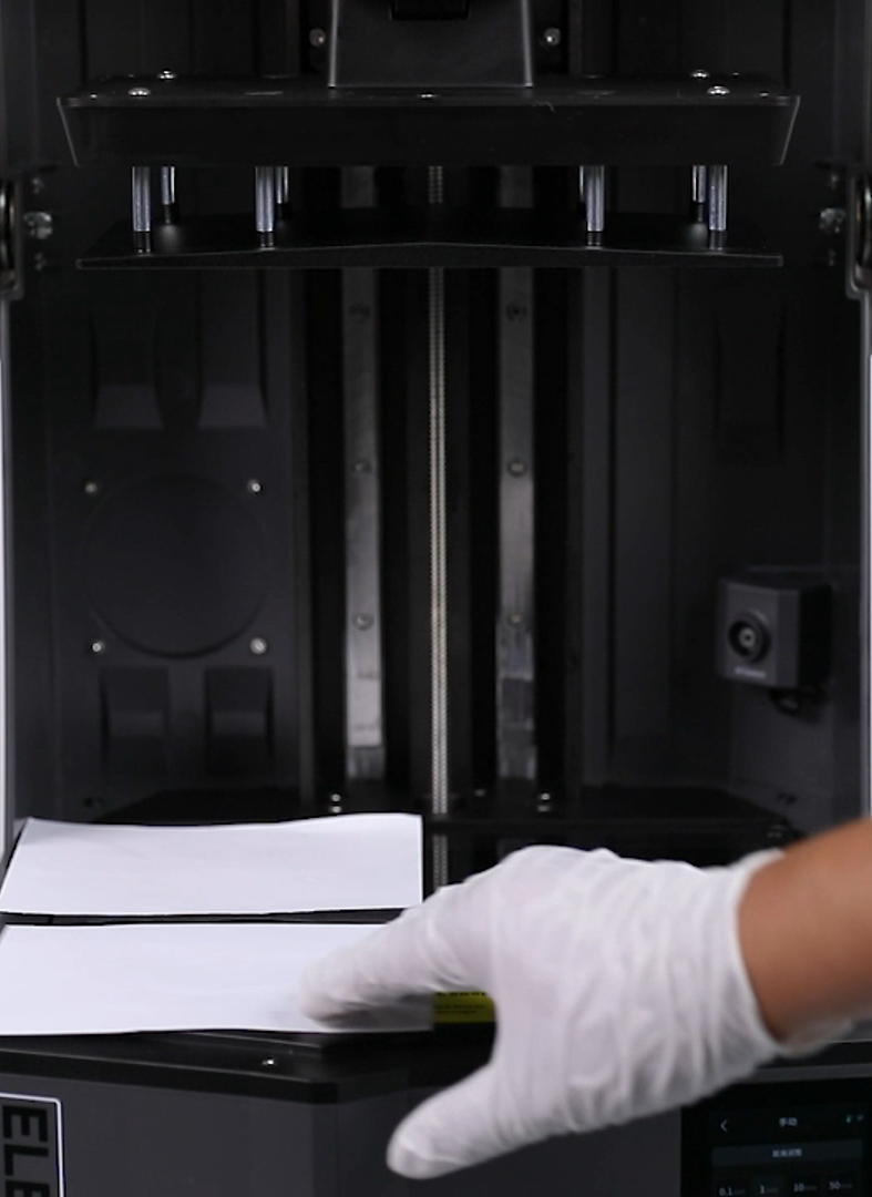
- Install the printing platform. Tear a piece of A4 paper into 4 equal pieces and place them at the four corners of the LCD screen.
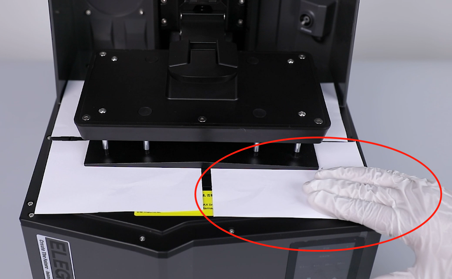
- Select "Tools - Manual" on the touchscreen. Lower the printimg platform by 50 mm, 10 mm, 1 mm and 0.1 mm to press the A4 paper.
- Pull the A4 paper at the 4 corners with your hand to make sure there is significant resistance.
- Use a 4.0 mm Allen wrench to tighten the 4 screws in diagonal direction securing the cantilever junction blocks.
- Select "Home" on the touchscreen, the Z-aixs starts its homing process. Then, remove the A4 paper.

- Remove the build pate. Use a 4.0 mm Allen key to loosen the screw securing handle. then remove the handle. When the screw is about to come loose, hold the handle with your other hand to prevent it from falling.
- Align the clips and press the protective cover back into place.
- Prepare the handle. Put it in the installation position by aligning it with the screw holes. Use a 4.0 mm Allen key to tighten the screw securing the handle.
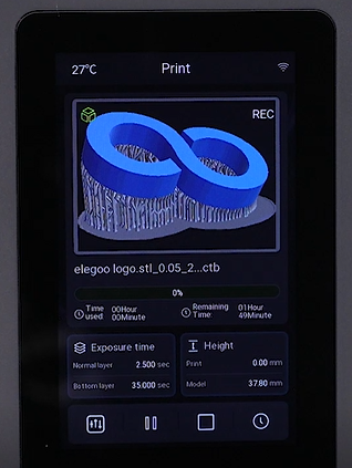
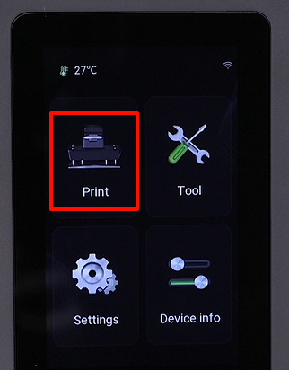
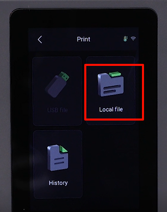
- After installing the build plate and resin tank, touch "Print - USB file" on the touchscreen and select the model to be printed.
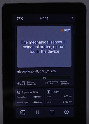
- Observe the touchscreen. It displays ‘Calibrating the sensor - detecting resin - automatic leveling’ and function detection is normal without any abnormal alarm. It means that the spring wire replacement and leveling compeltes. The printer is ready for use.