¶ Tools and Materials
- A 2.0 mm Allen wrench
- A 2.5 mm Allen wrench
- A new X-axis limit switch
¶ Tutorial Video
¶ Instruction
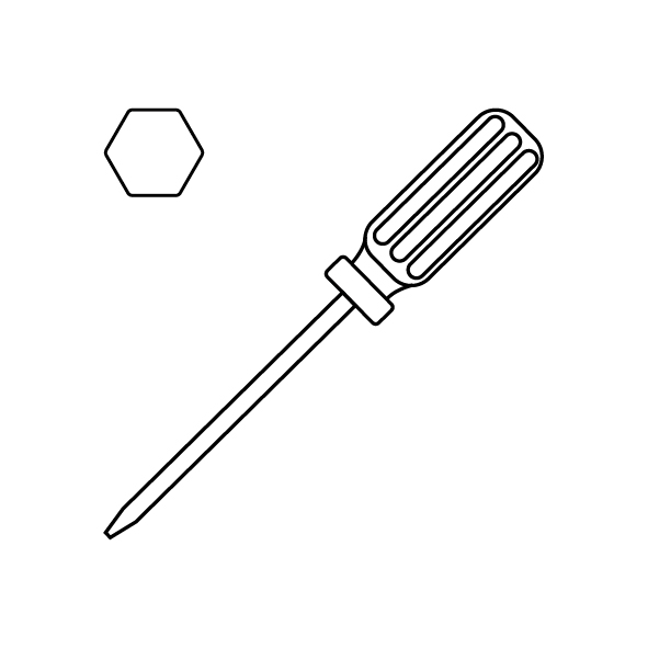
- Power off the printer and unplug the power cord.
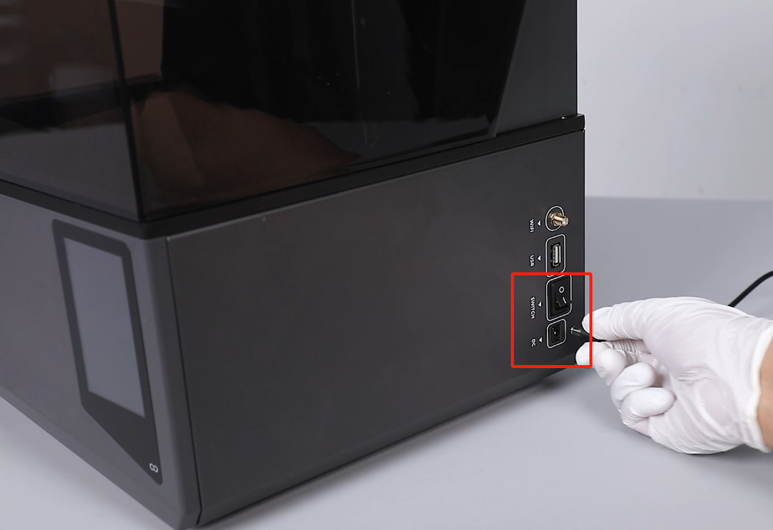
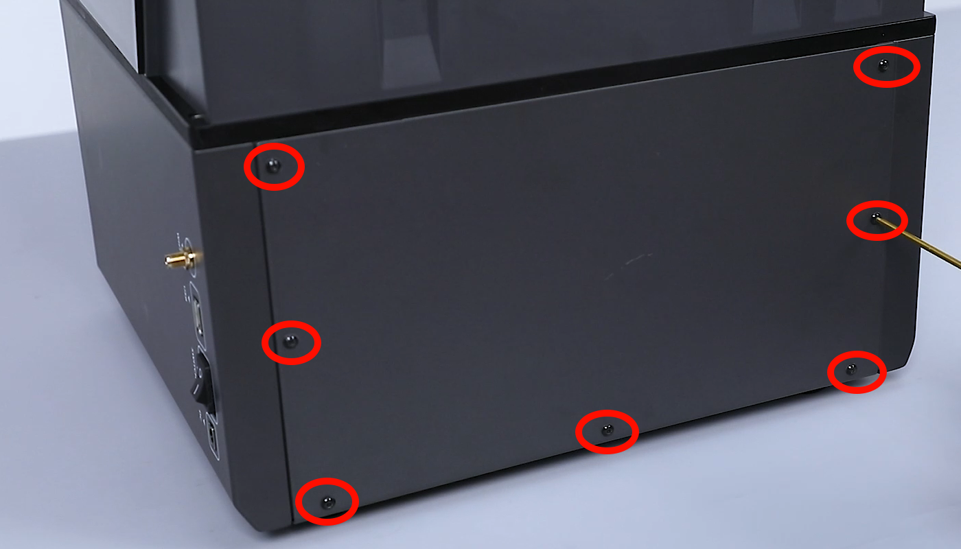
- Use a 2.0 mm Allen key to loosen the 7 screws securing the back cover of the printer and remove the back cover.
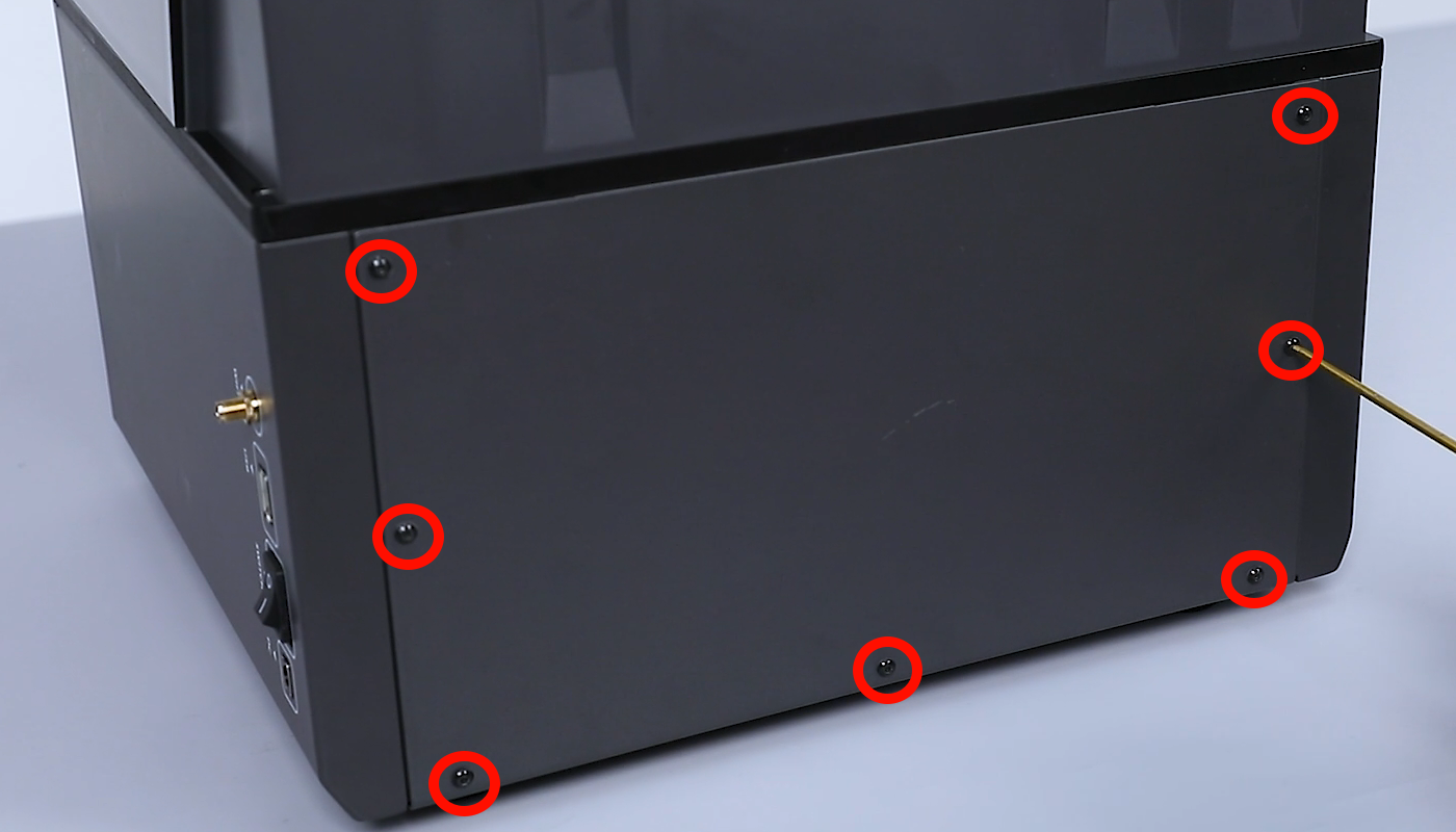
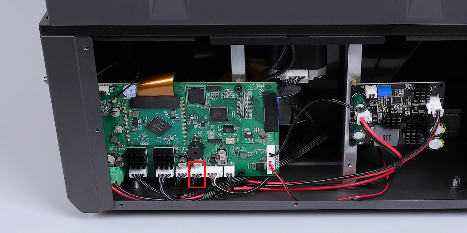
- Unplug the ribbon cables of the X-axis limit switch port on the motherboard.
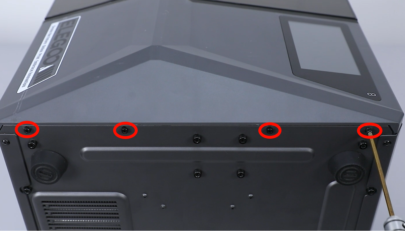
- Lift the top cover. Use a 2.5 mm Allen wrench to loosen the 4 screws fixed at the upper part of the front cover.
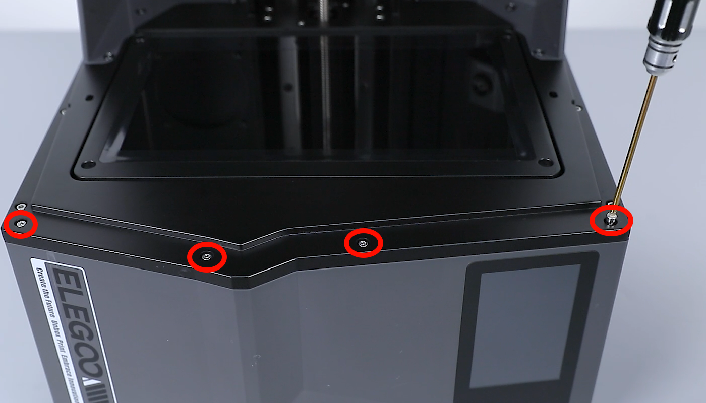
- Close the top cover and loosen the 4 screws fixed at the lower part of the front cover using a 2.5 mm Allen wrench.

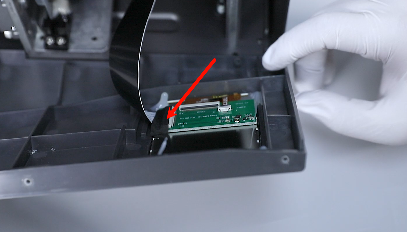
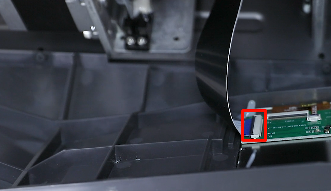
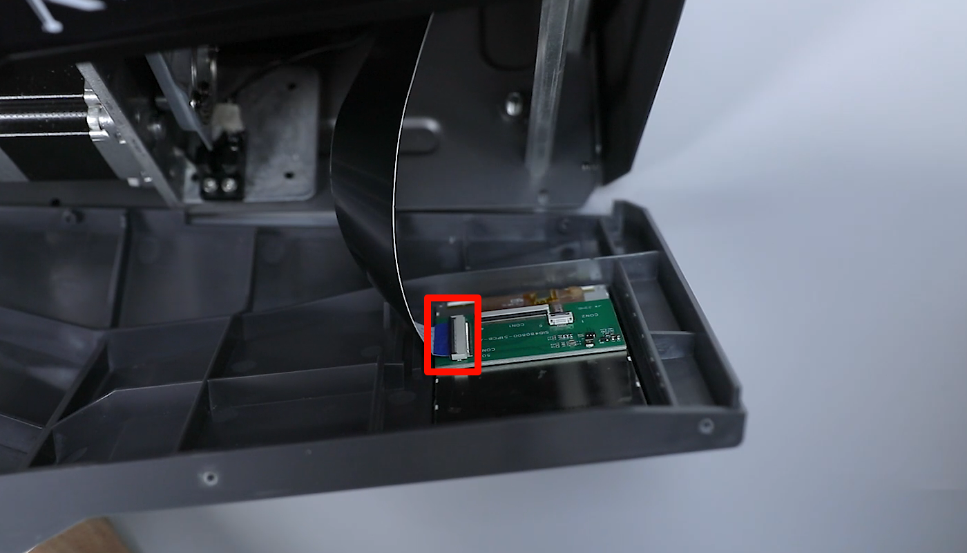
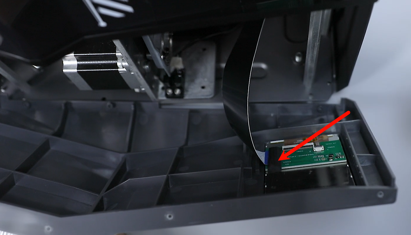
- Open the front cover a little slit and peel off the black tape adhered to the the touchscreen port. Disconnect the ribbon cables of the the touchscreen port. Ttake out the front cover.
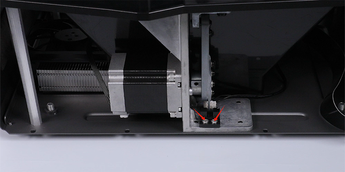
- Loosen the 2 screws securing the X-axis limit switch using a 2.5 mm Allen wrench.
- Organize the cable. Remove the X-axis limit switch assembly.
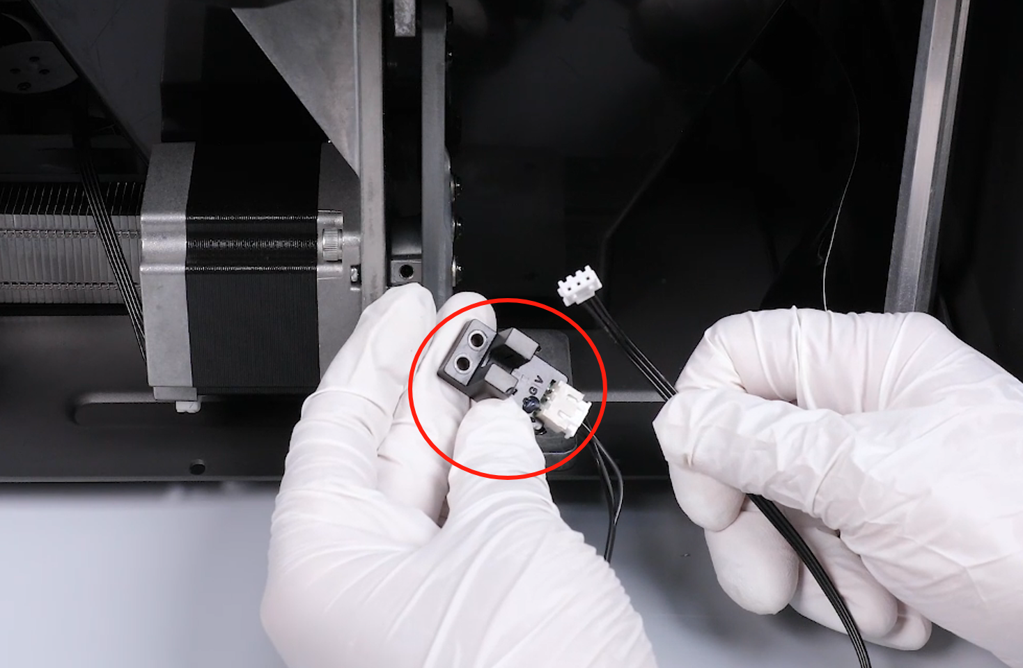
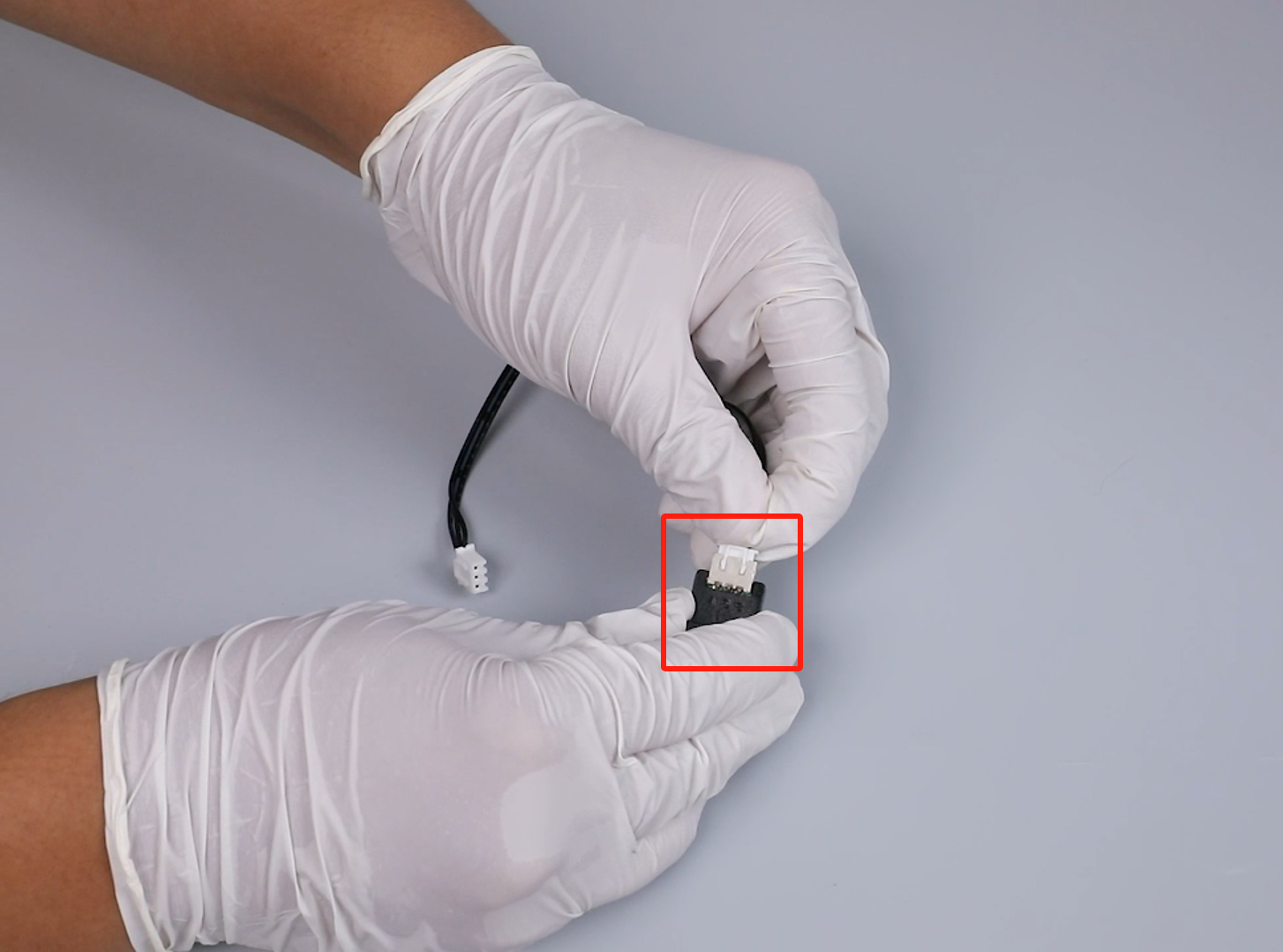
- Unplug the ribbon cables of the X-axis limit switch por.
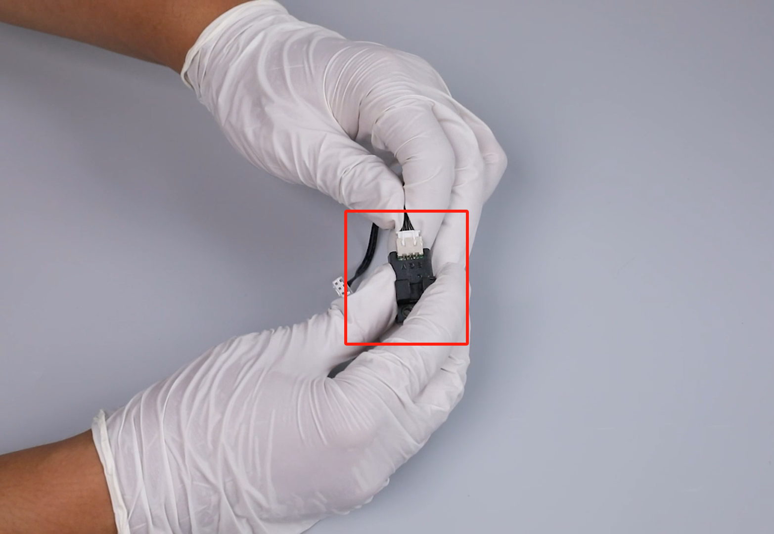
- Prepare the new X-axis limit switch. Insert the ribbon cables of the Z-axis limit switch port.
- Prepare the new X-axis limit switch assembly and put it in the installation position. Tighten the 2 screws securing the X-axis limit switch using a 2.5 mm Allen wrench.

- Place the front cover in the installation area in the front of the printer. Insert the touchscreen cable into the touchscreen port.
Note: The touchscreen ribbon cables have a fixed installation position.
- Stick the black tape to the port of the touchscreen ribbon cables.
- Put the front cover in the installation position by aligning it with the screw holes. Use a 2.5 mm Allen wrench to tighten the 4 screws securing the upper part of the front cover.

- Use a 2.5 mm Allen wrench to tighten the 4 screws underneath the front cover.
- Remove the X-axis limit switch cable from the back of the printer using a L-shaped wrench.
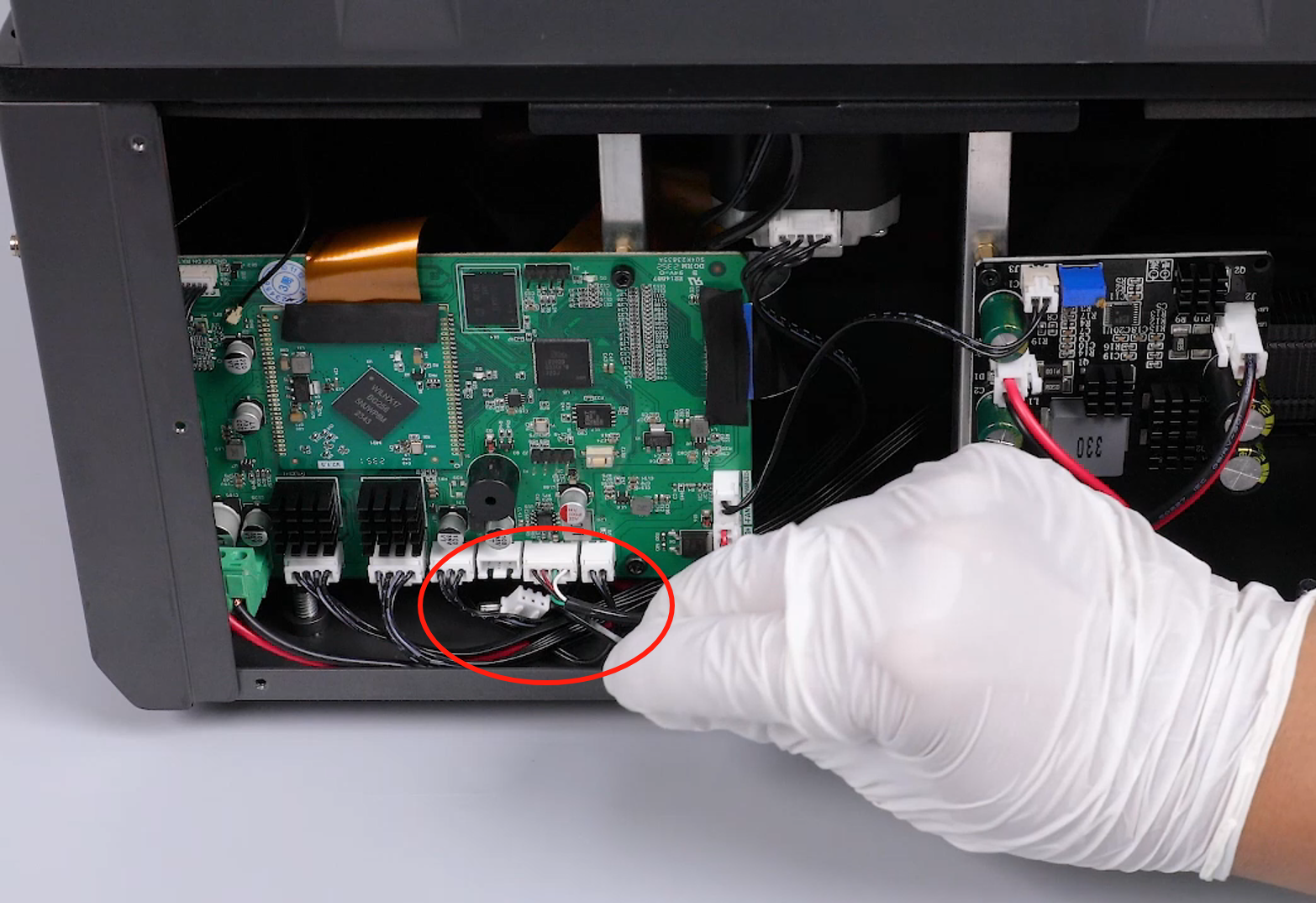
- Insert the ribbon cables of the X-axis limit switch into the port on the motherboard.
- Prepare the back cover of the printer. Use a 2.0 mm Allen wrench to tighten the 7 screws securing the back cover of the printer.
- Power on the printer. The printer is ready for use after its self-inspection.