¶ Tools and Materials
- A 2.0 mm Allen key
- A 2.5 mm Allen key
- A 3.0 mm Allen key
- A pair of diagonal pliers
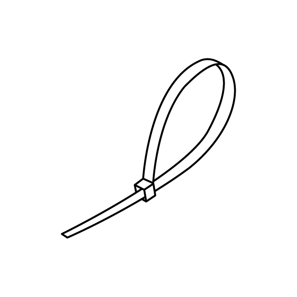
- Cable ties
- A new lead screw motor
¶ Tutorial Video
Coming soon.
¶ Instruction
- Power off the printer and unplug the power cord.
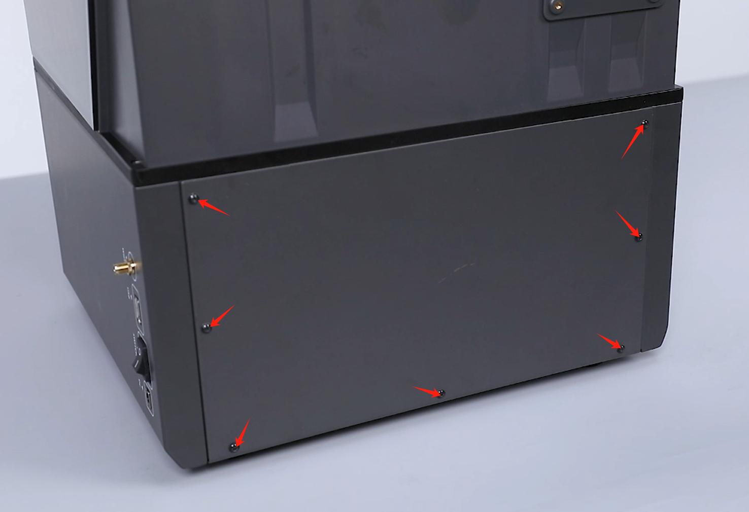
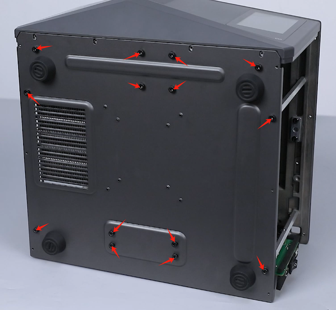
- Loosen the 7 screws securing the back cover of the printer using a 2.0 mm Allen key and remove the back cover.
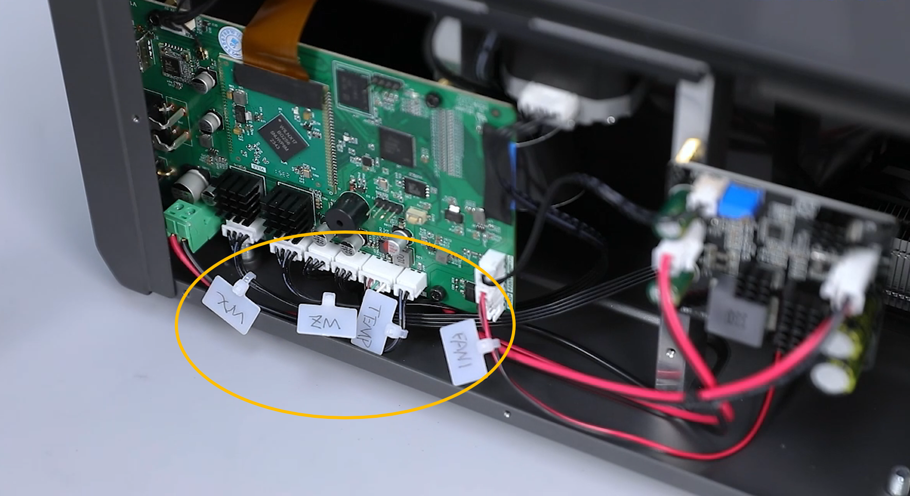
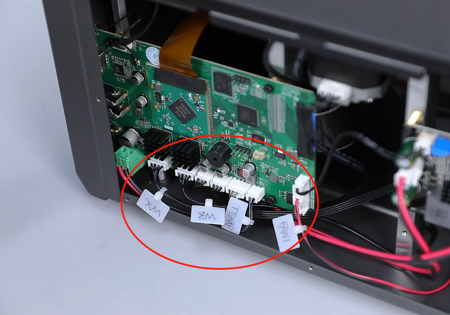
- Mark the cable ports of the same size using labels or label ties to correspond to the names of the ports on the motherboard.
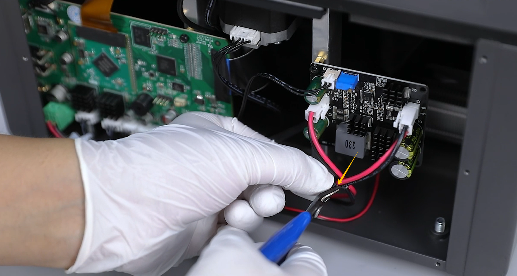
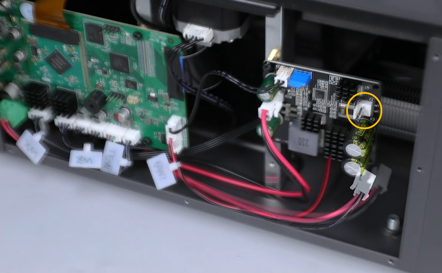
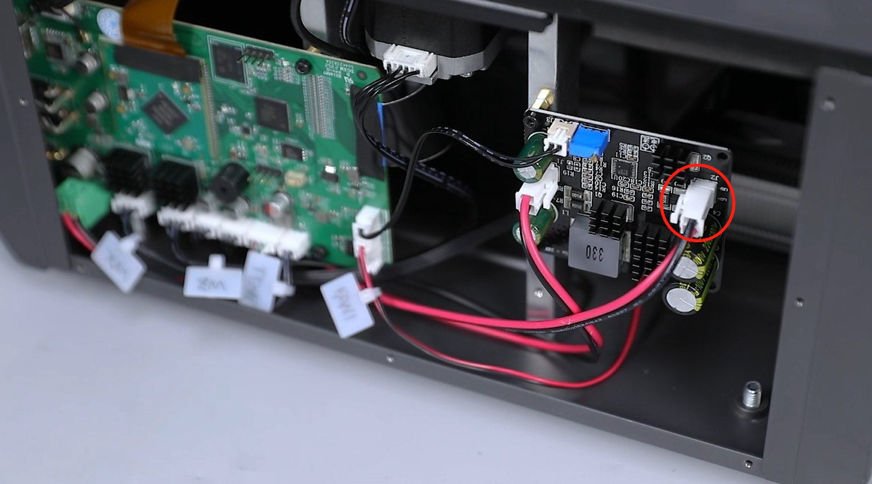
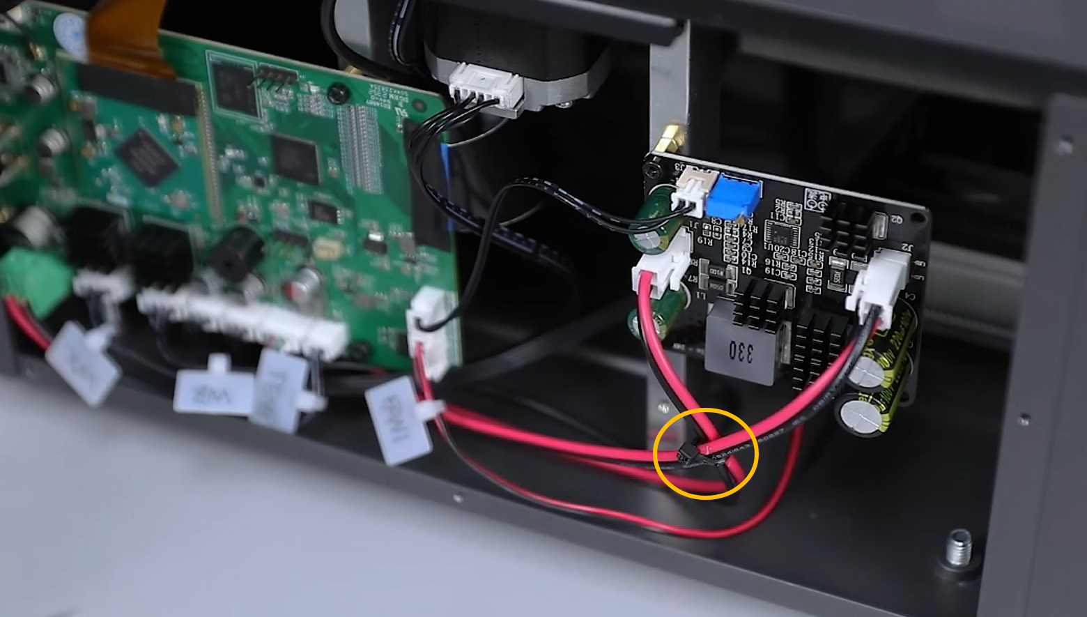
- Cut off the cable ties securing the UV light cables using a pair of diagonal pliers. Unplug the ribbon cables of the J2 port (UV light) on the motherboard.
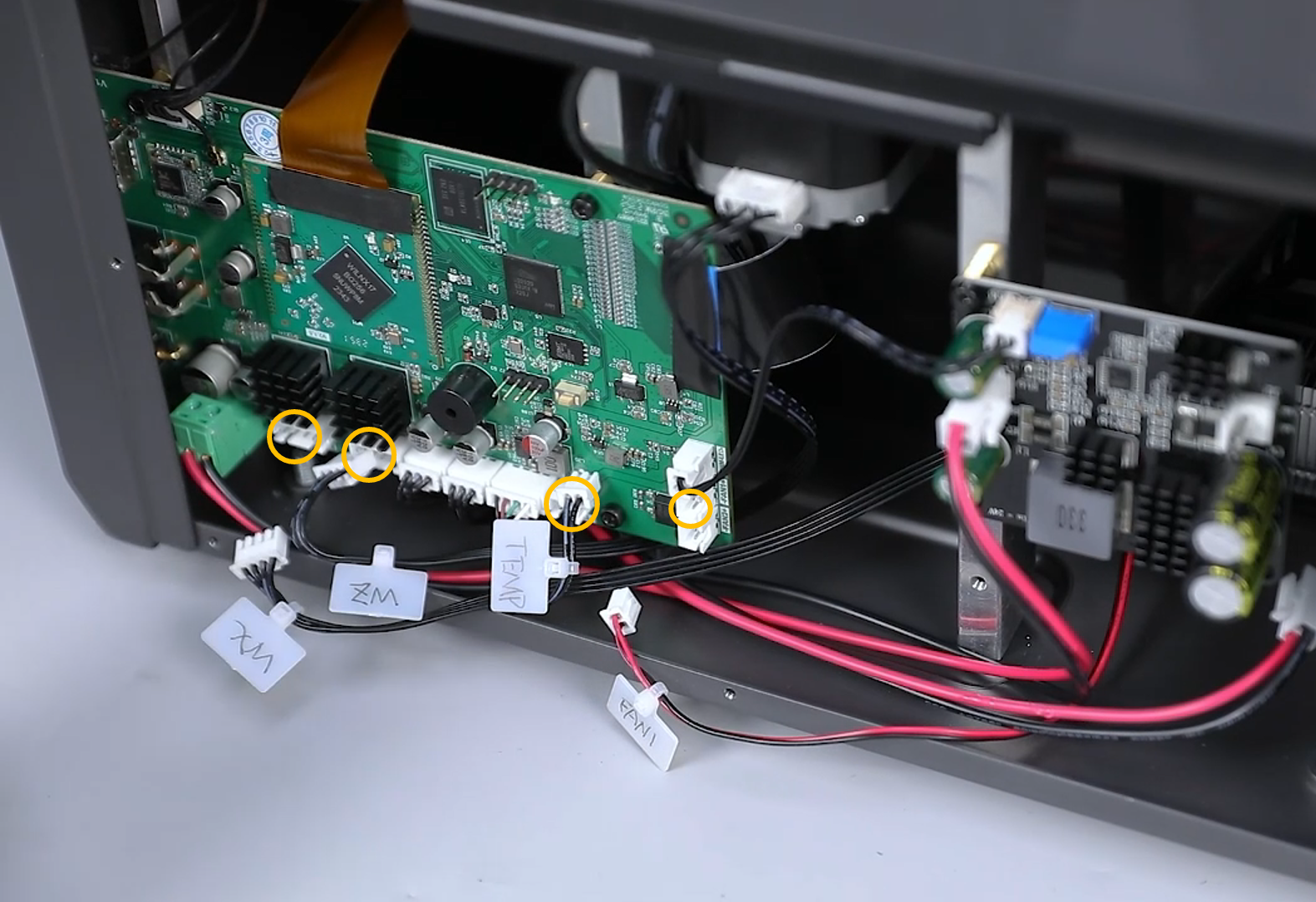
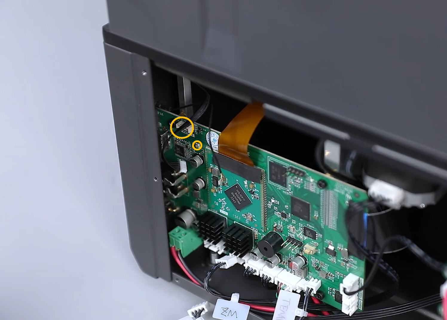
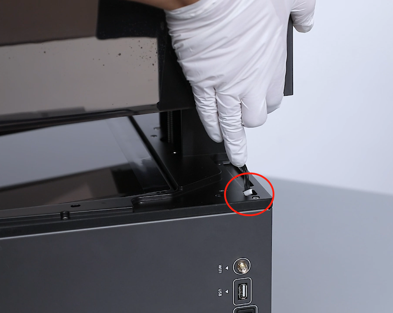
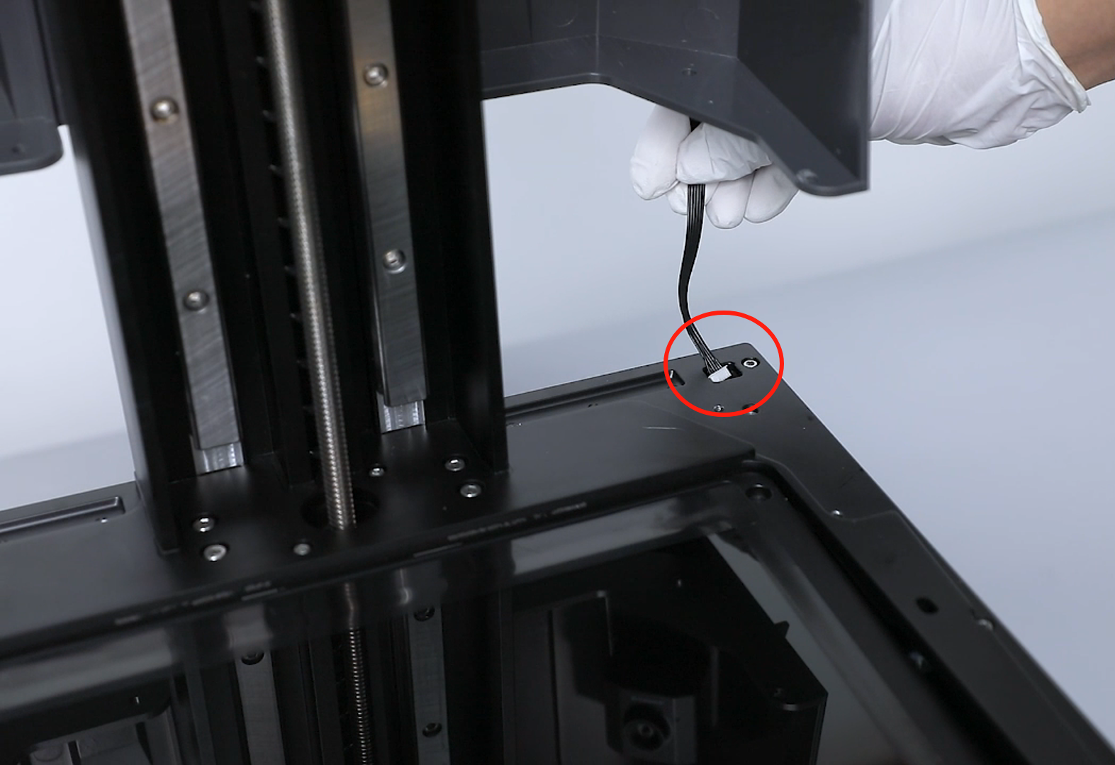
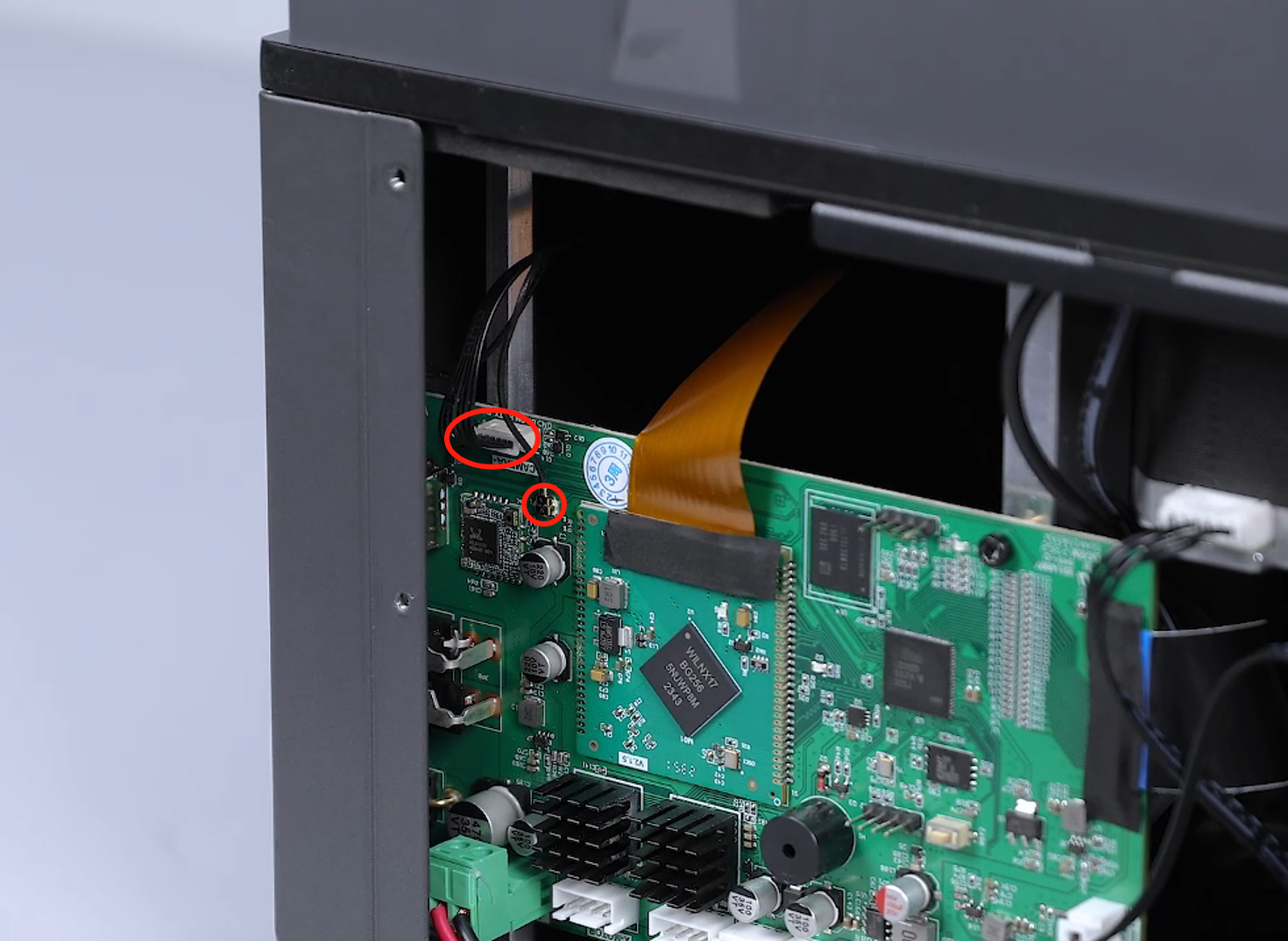
- Unplug the ribbon cables of the FAN1 port, TEMP port, X-MOTOR port, Z-MOTOR port, Wifi port, CAMERA port on the motherboard.
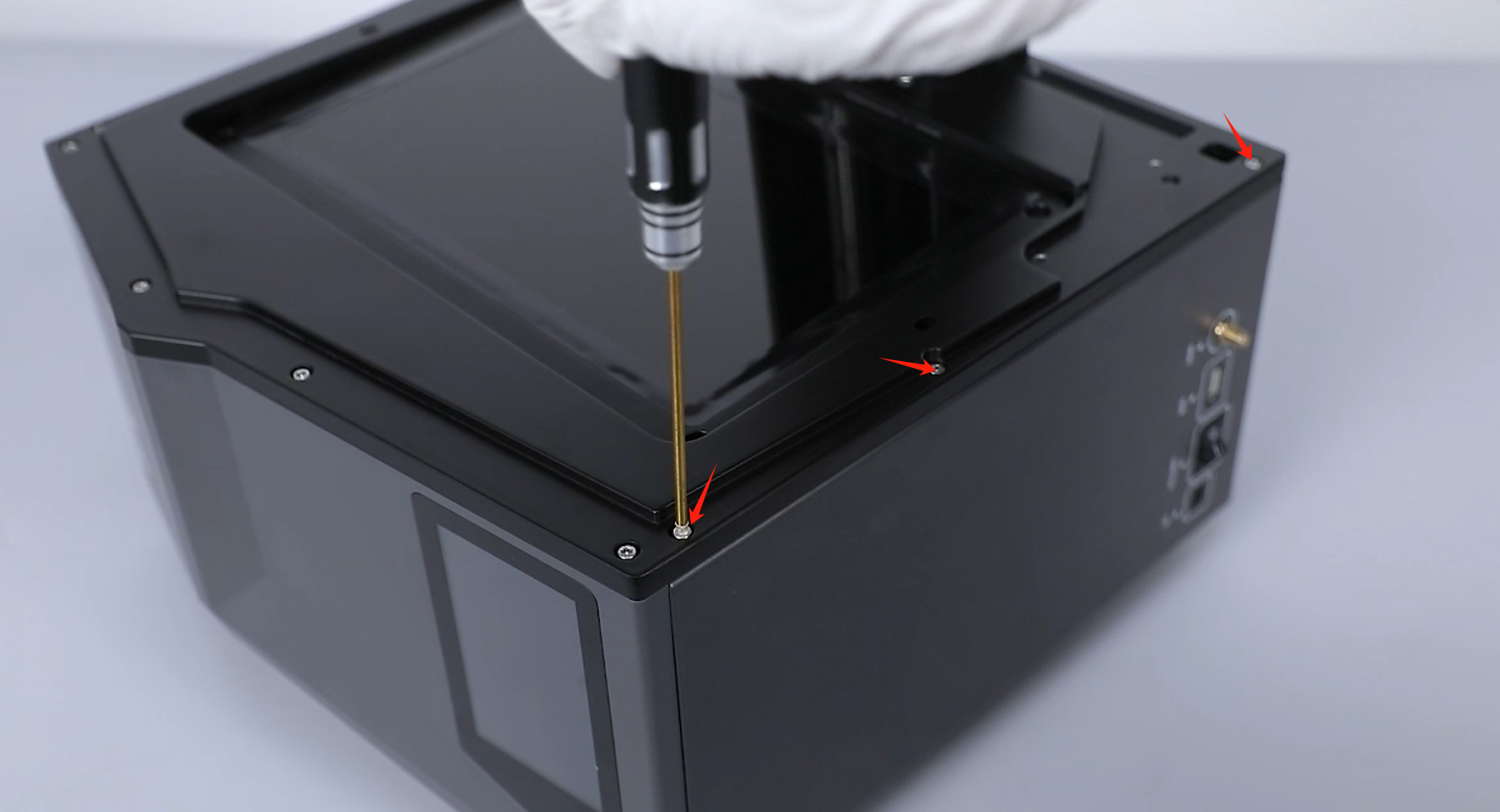
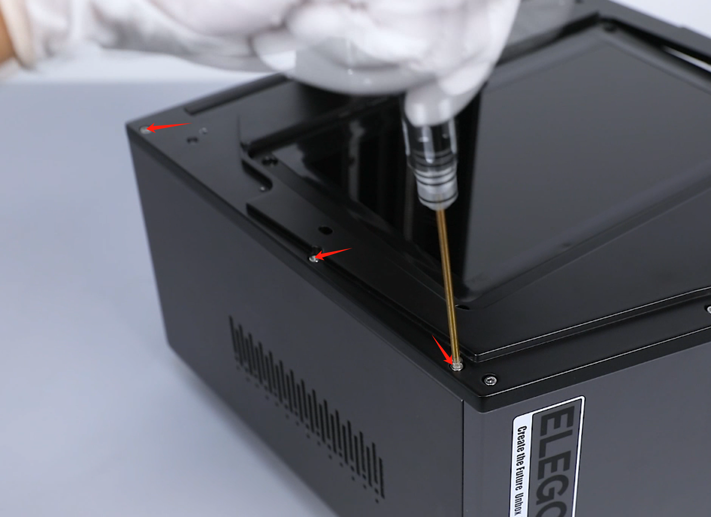
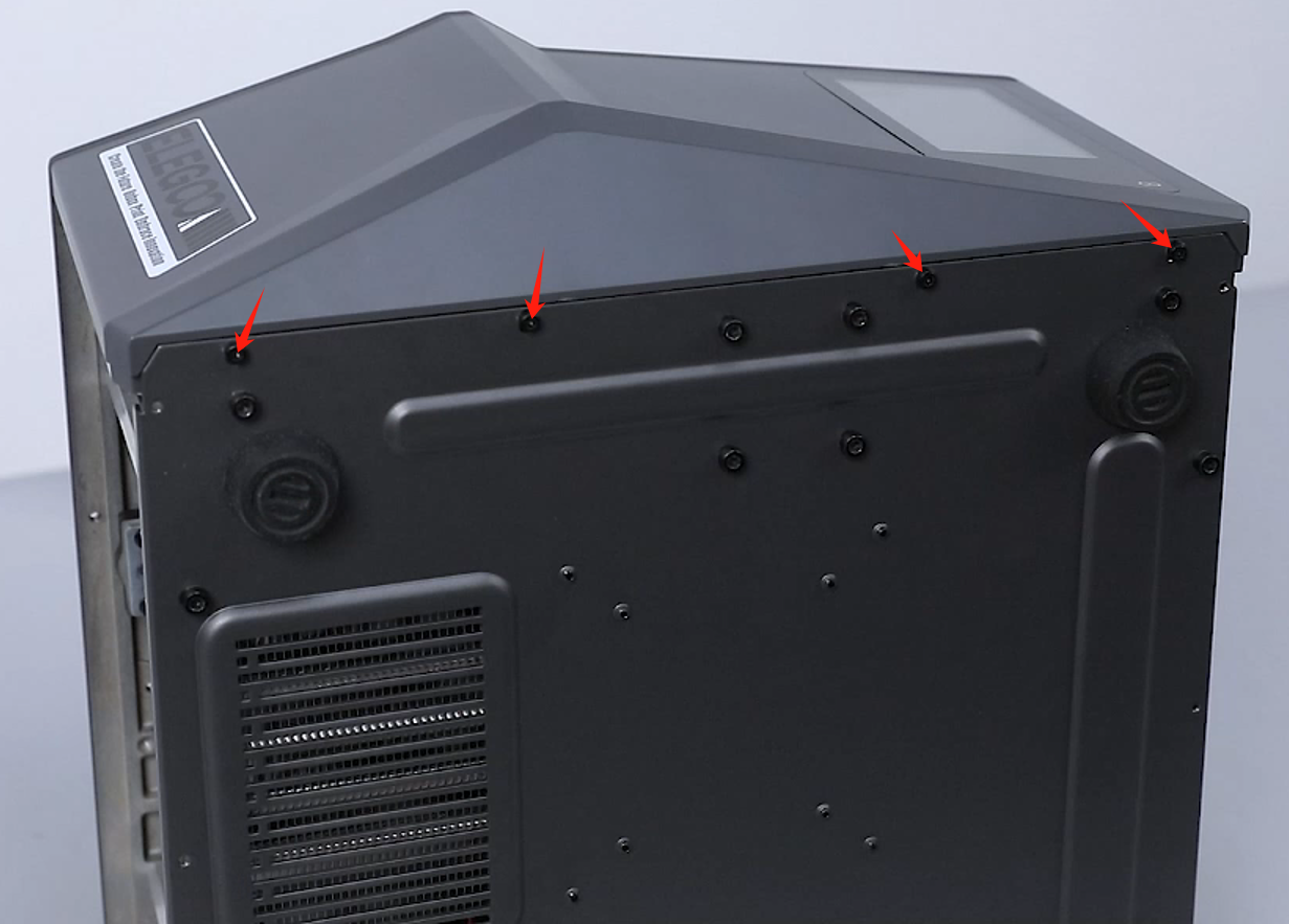
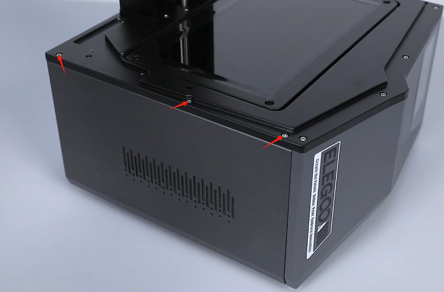
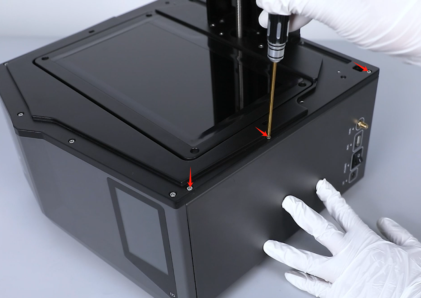
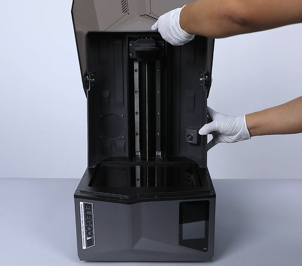
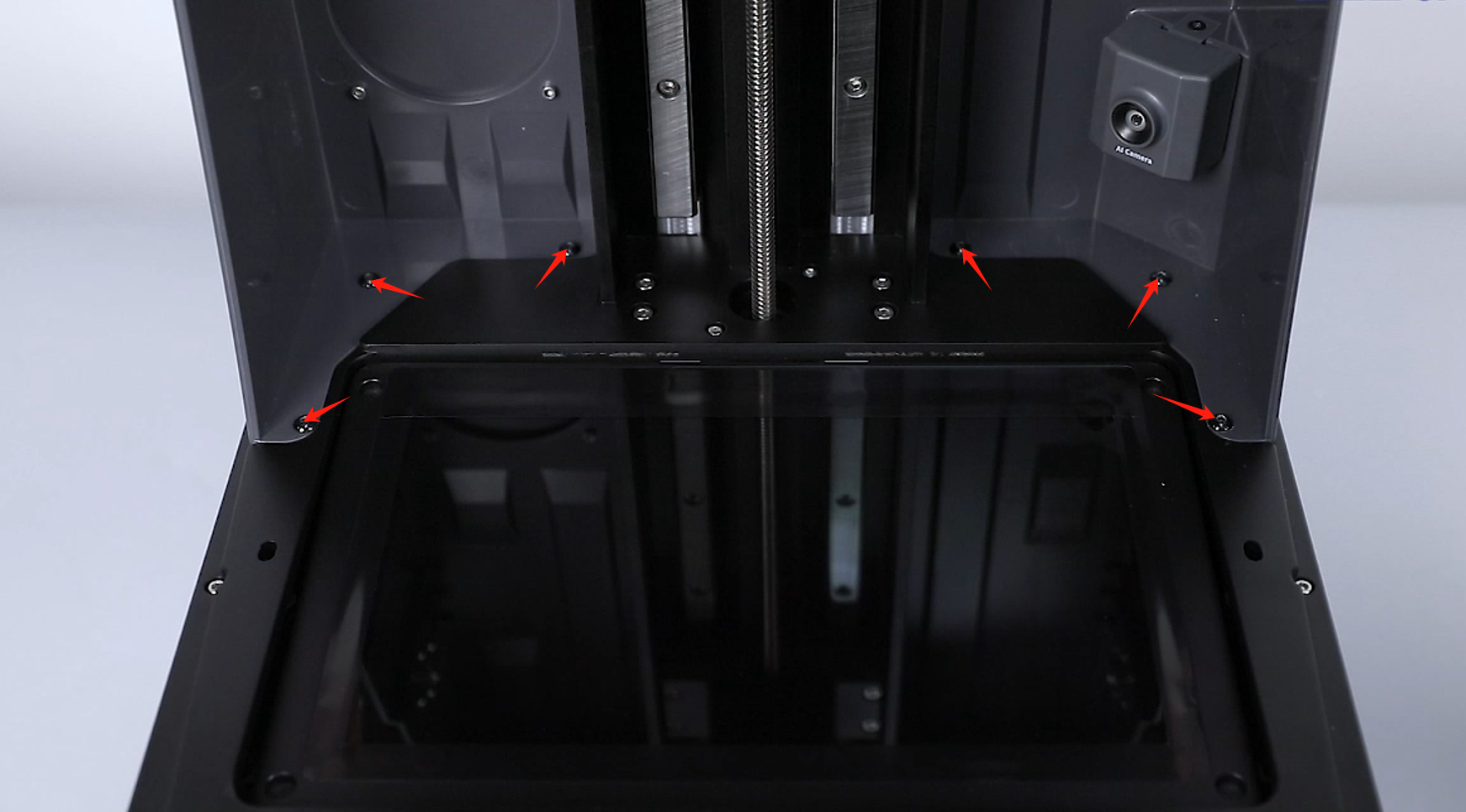
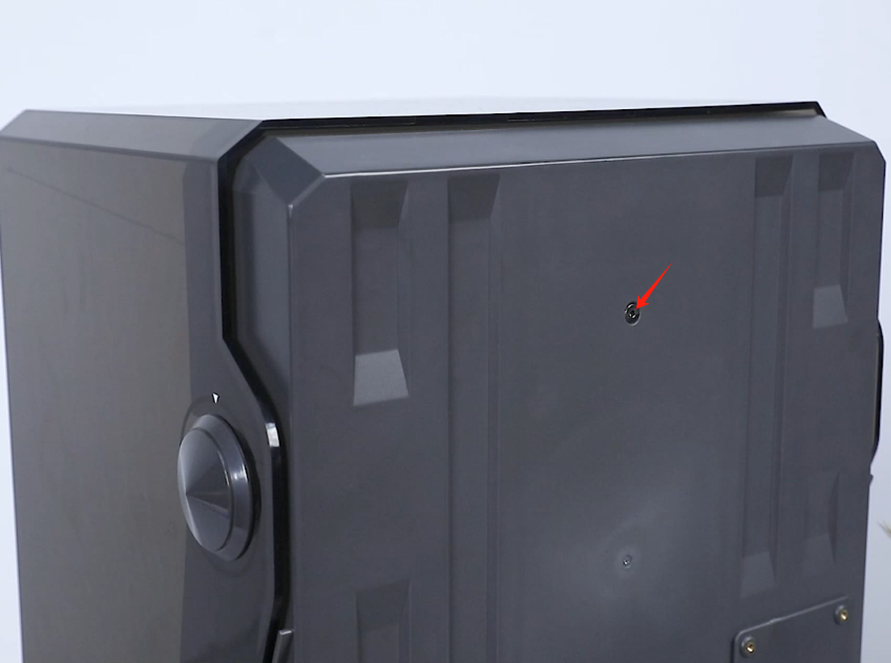
- Loosen the 6 screws fixed at the lower part of the top cover and the screw at the back side of the top cover using a 2.5 mm Allen key.


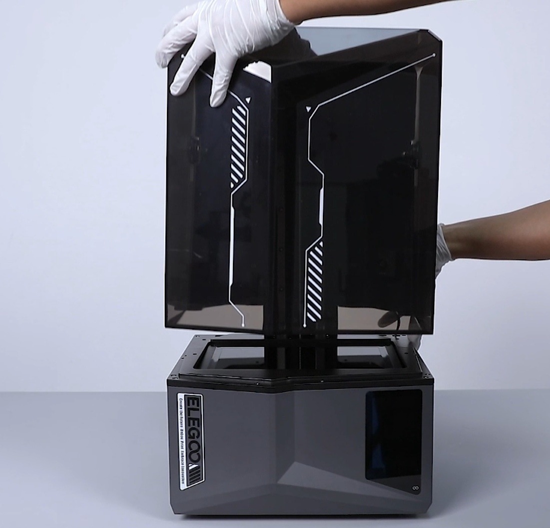
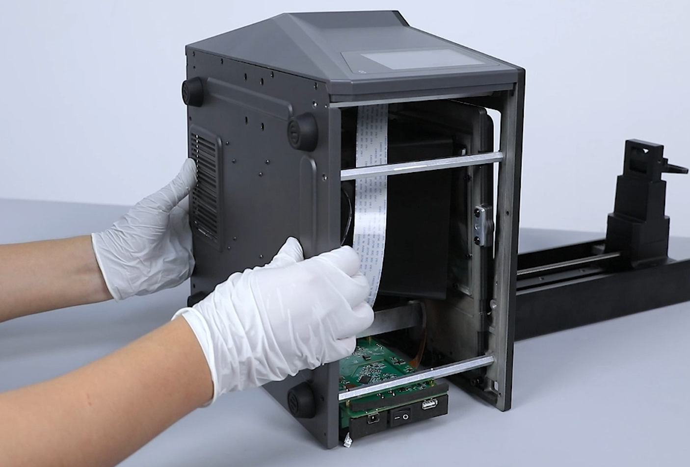
- Remove the top cover of the printer.
Note: Tidy up the ribbon cables of the camera in the reserved holes at the right side.
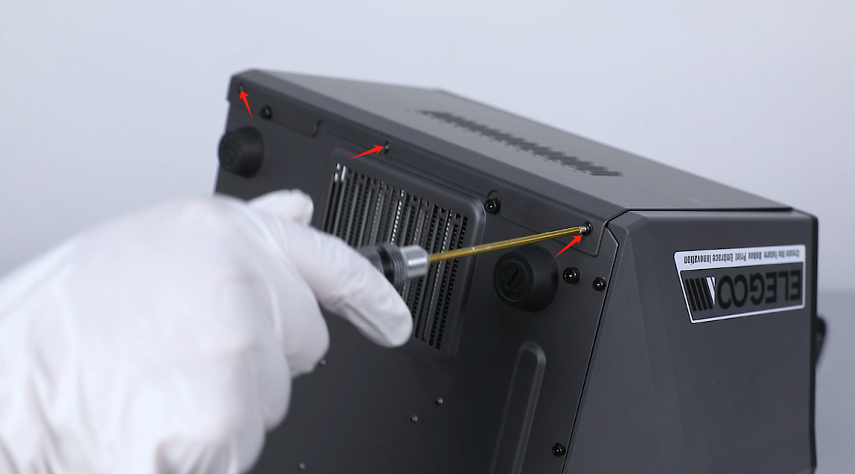
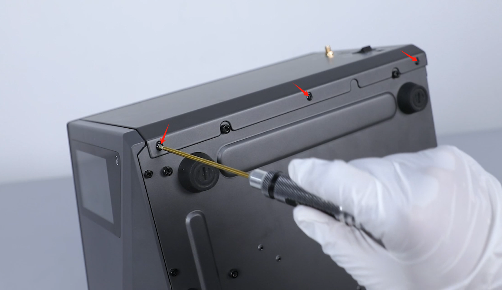
- Loosen the 3 screws fixed at the upper part of the right cover using a 2.5 mm Allen key.
- Use a 2.0 mm Allen key to loosen the 3 screws securing the lower side of the printer's right cover, then remove the right cover.

- Loosen the 3 screws fixed at the upper part of the left cover using a 2.5 mm Allen key.
- Use a 2.0 mm Allen key to loosen the 3 screws securing the lower side of the printer's left cover, then remove the left cover.
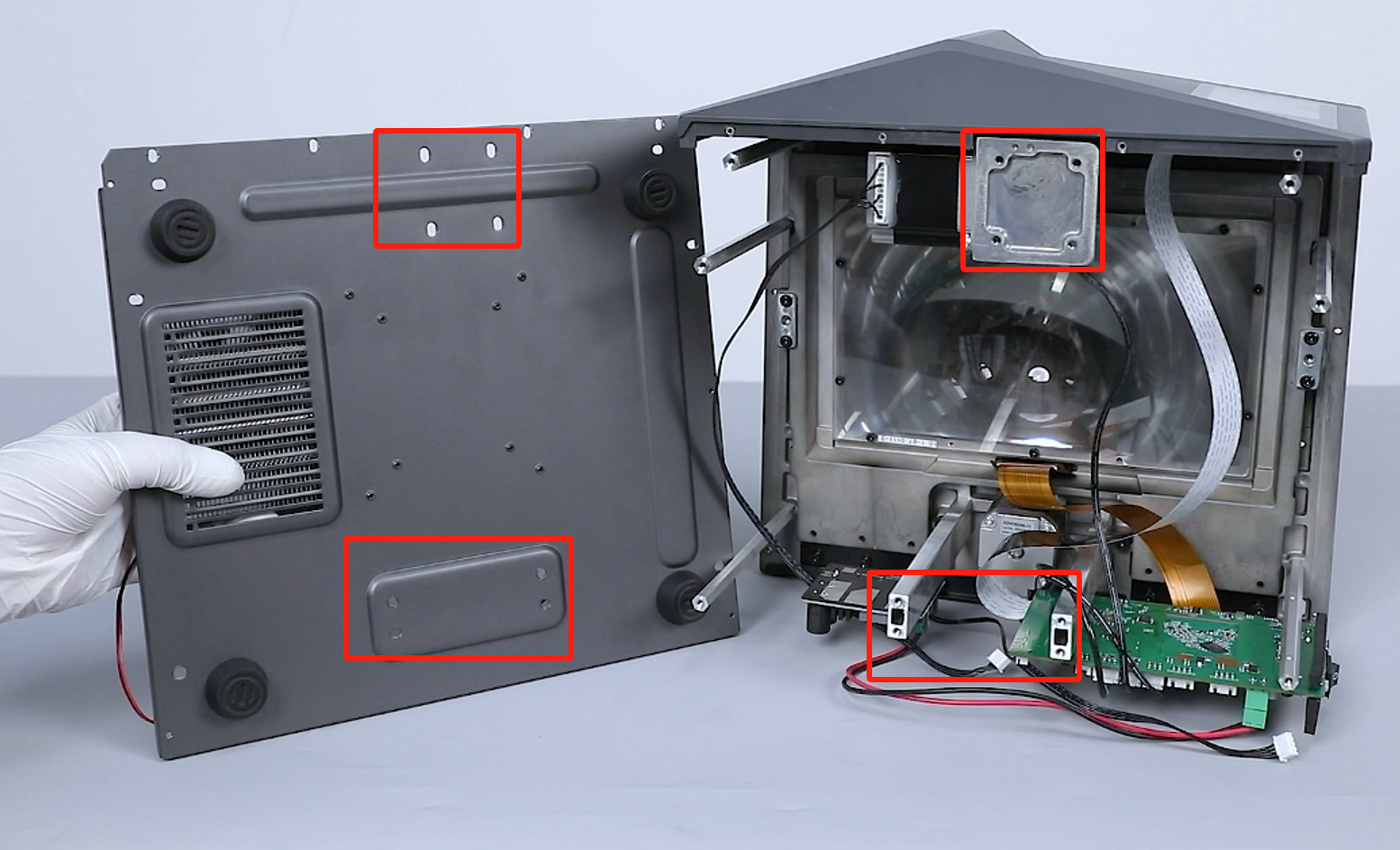
- Loosen the 4 screws underneath the front cover using a 2.5 mm Allen key.

- Loosen the 14 screws securing the bottom cover of the printer using a 3.0 mm Allen key and remove the bottom cover assembly.
Note: Hold the back cover to prevent it from falling while loosening the last 2 screws.
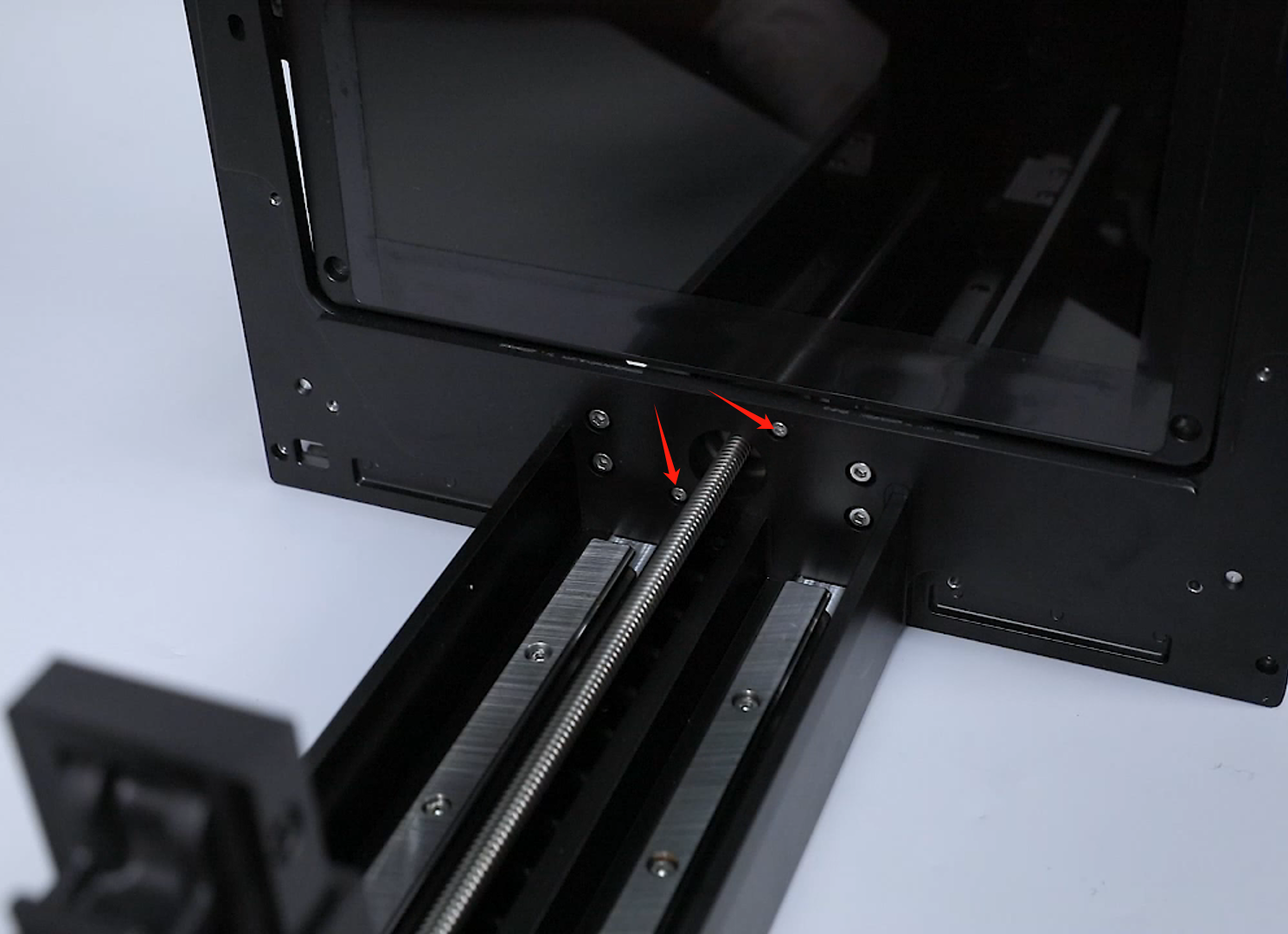
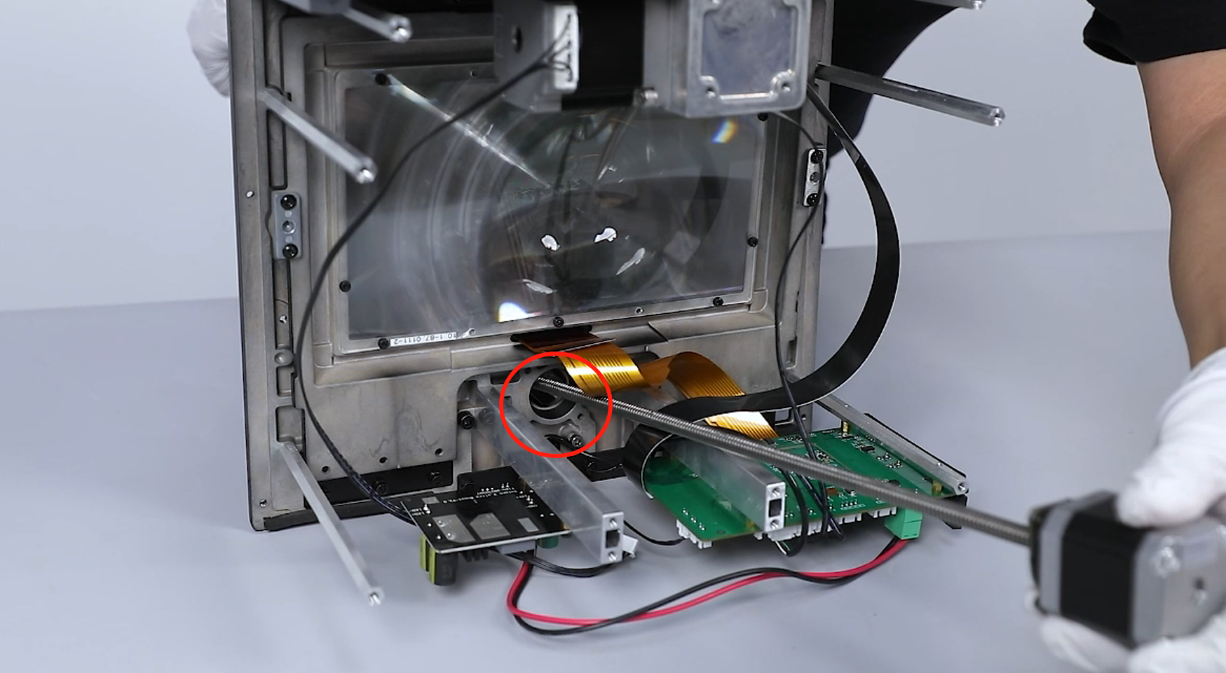
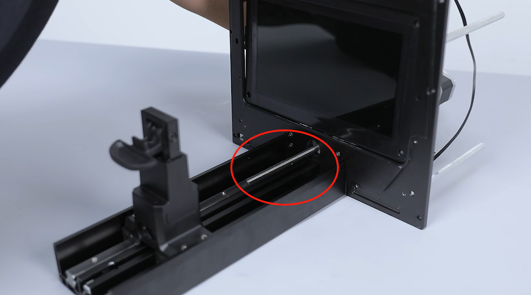
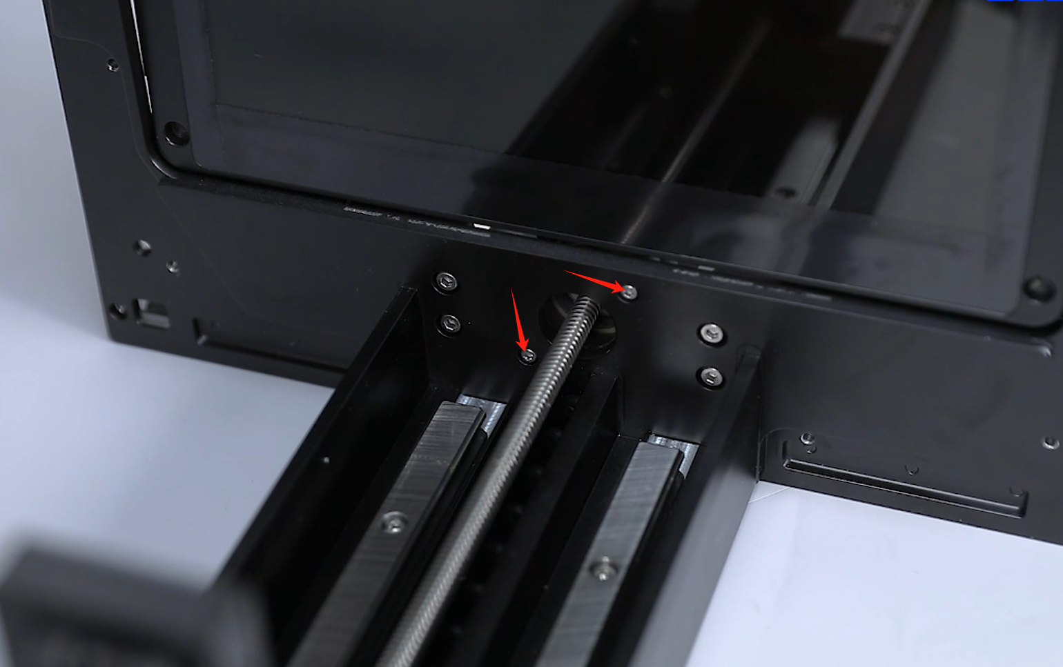
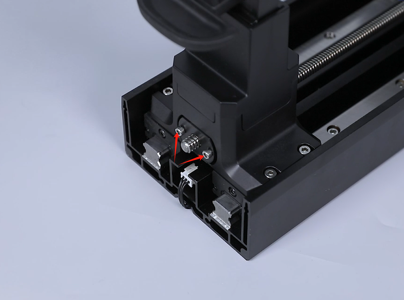
- Loosen the 2 screws securing the nut using a 2.5 mm Allen key.
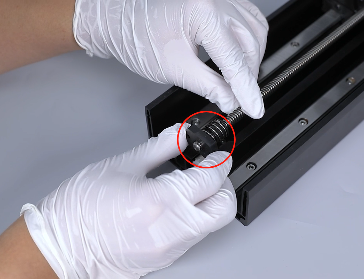
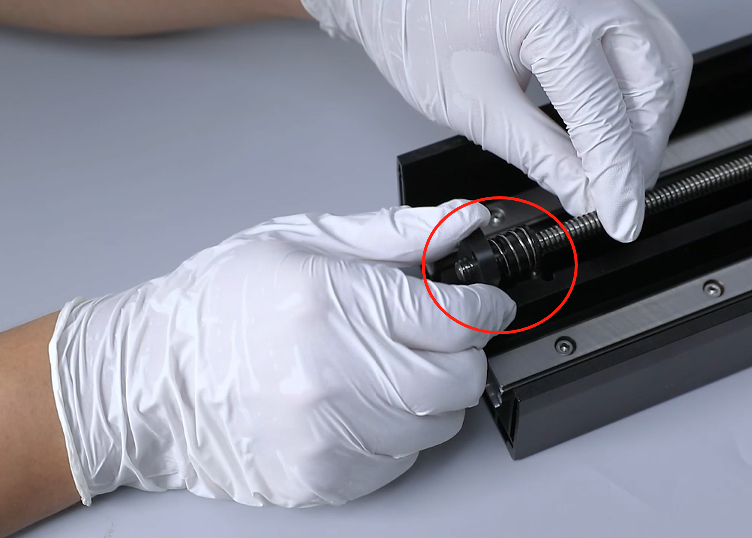
- Hold the lead screw with one hand and turn the nut with the other hand to remove it from the top of the lead screw.
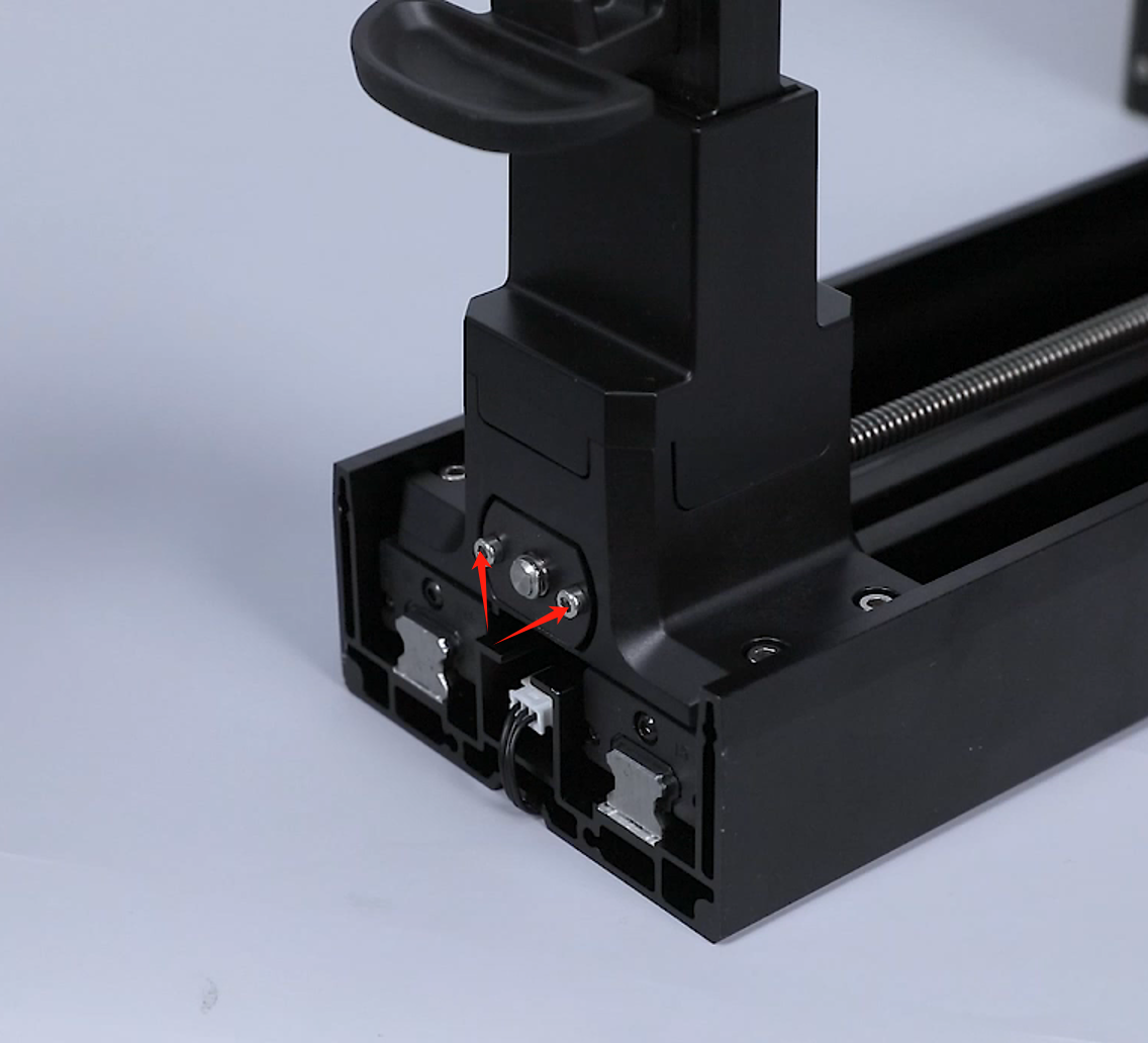
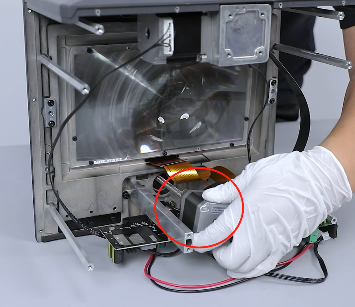
- Loosen the 2 screws securing the motor using a 2.5 mm Allen key.
Note: Hold the motor to prevent it from falling while loosening the last screw.
- Remove the motor assembly from the back of the printer.
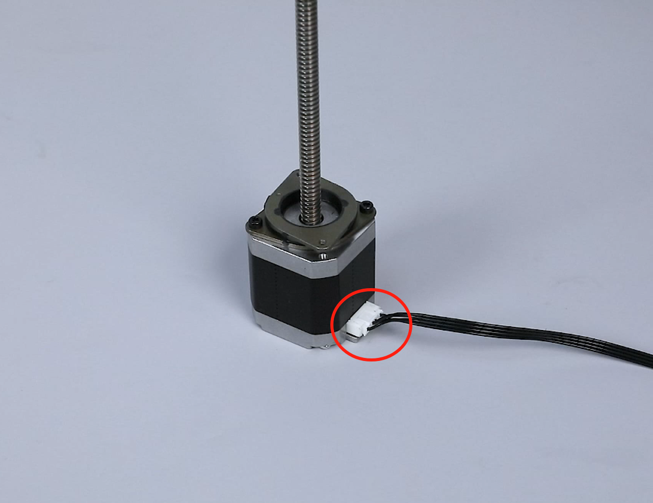
- Unplug the ribbon cables of the motor.
- Loosen the 2 screws securing the shock absorbing pads using a 2.5 mm Allen key.
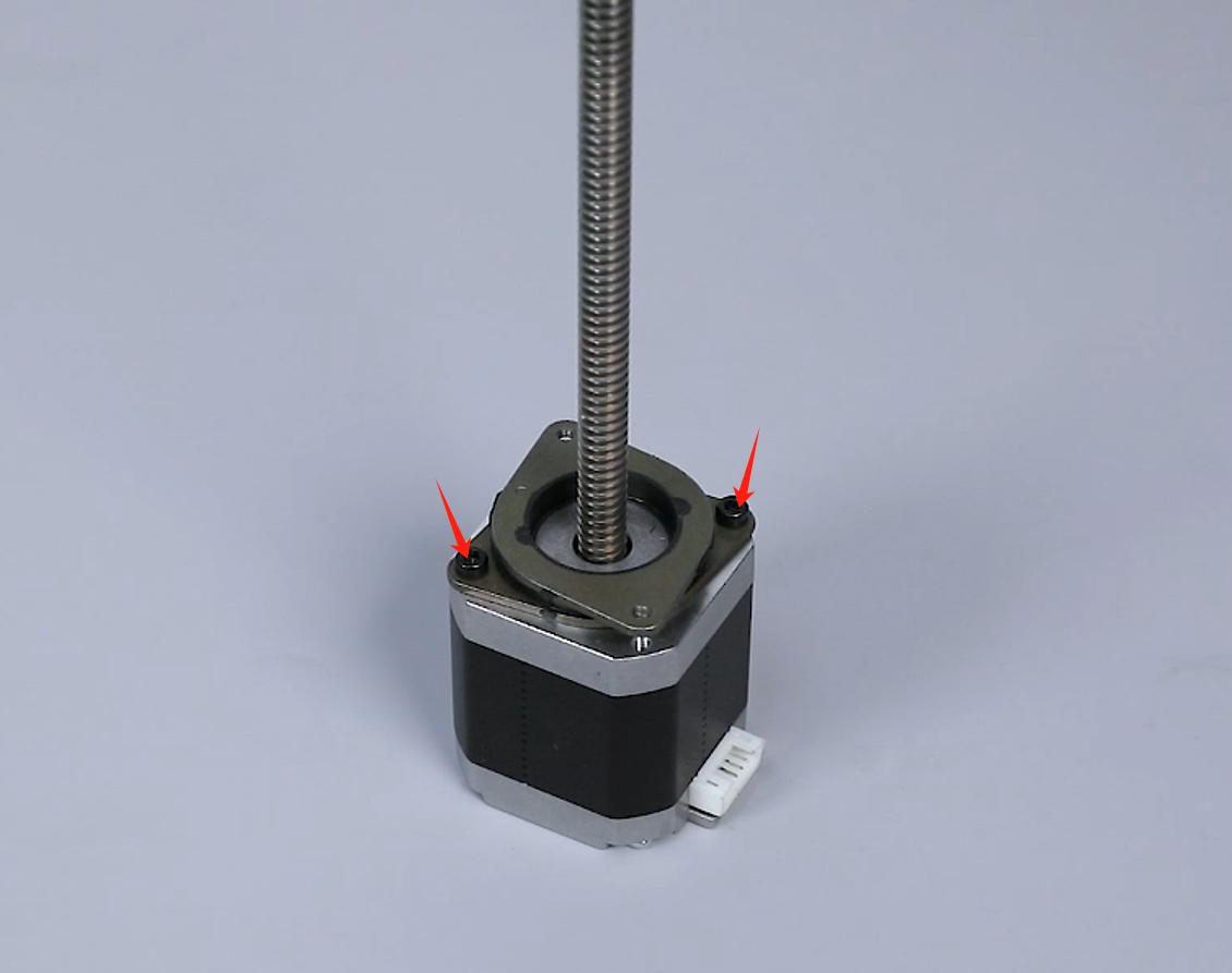
- Prepare the new motor. Align the shock absorbing pads with the screw holes and put it in the installation position. Tighten the 2 screws that secure the motor using a 2.5 mm Allen key.

- Insert the ribbon cables of the motor.

- Put the motor assembly in the installation position by aligning it the the screw holes.
- Tighten the 2 screws securing the motor by third-fourths depth using a 2.5 mm Allen key several times.
- Remove the nut. Hold the lead screw with one hand and turn the nut with the other hand to remove it from the top of the lead screw.
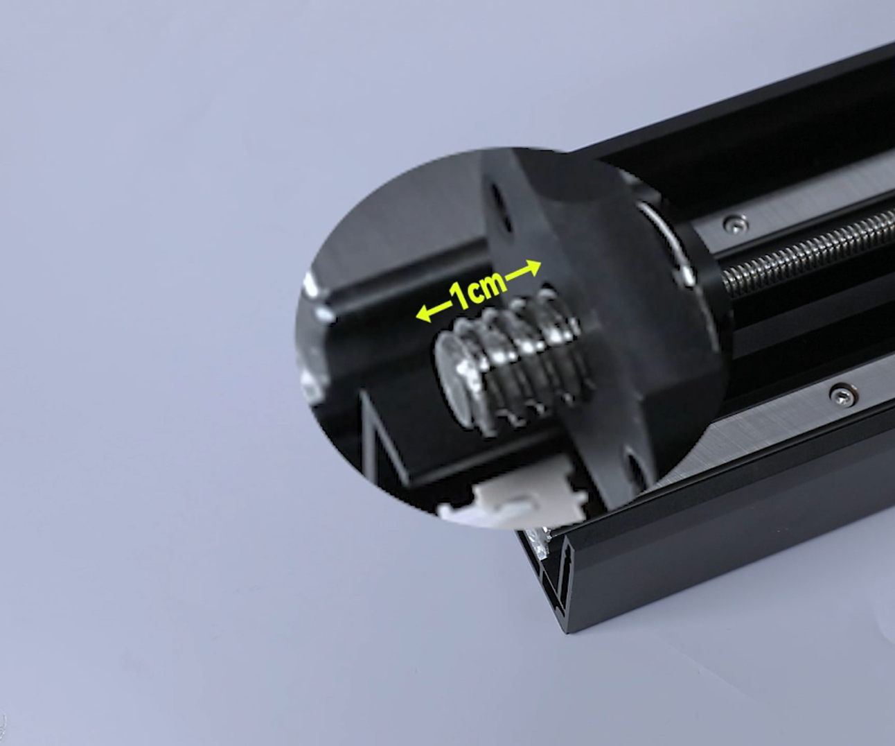
Note: Screw the nut to about 1 cm from the top of the lead screw.
- Tighten the 2 screws securing the nut by third-fourths depth using a 3 mm Allen key.
Note: The 2 screws should be tighten completely subsequently.
- Prepare the bottom cover assembly. Distinguish the direction of the bottom cover installation direction according to the position of the screw holes on the bottom cover. Align the bottom cover assembly with the screw holes and put it installation position.
Note: Tidy up the ribbon cables to avoid being crushed during installation.
- Use a 3.0 mm Allen key to loosen the 14 screws securing the bottom cover.

- Loosen the 4 screws underneath the front cover using a 2.5 mm Allen key.
- Prepare the left cover. Put the left cover in the installation position by aligning it with the screw holes. Tighten the 3 screws securing the upper part of the front cover using a 2.5 mm Allen key.
- Tighten the 3 screws fixed at the lower part of the left cover using a 2.0 mm Allen key.

- Prepare the right cover. Organize the Wi-Fi cable. Align the cover with the button holes and screw holes and put it in the installation position. Tighten the 3 screws securing the upper part of the front cover using a 2.5 mm Allen key.
- Tighten the 3 screws fixed at the lower part of the right cover using a 2.0 mm Allen key.
- Prepare the top cover of the printer. Put the top cover in the installation position by aligning it the the screw holes.
Note: Tidy up the ribbon cables of the camera in the reserved holes at the right side.
- Tighten the 6 screws fixed at the lower part of the top cover and the screw at the back side of the top cover using a 2.5 mm Allen key.
- Insert the camera cable into the CAMERA port on the motherboard. Insert the Wi-Fi cable on the port on the motherboard.
- Insert the ribbon cables into the ports on the motherboard according to the lable information.
- Insert the ribbon cables of the UV light into the J2 port on the constant current board.
- Secure the UV light ribbon cables using cable ties.
- Prepare the back cover of the printer. Use a 2.0 mm Allen wrench to tighten the 7 screws securing the back cover of the printer.

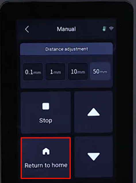
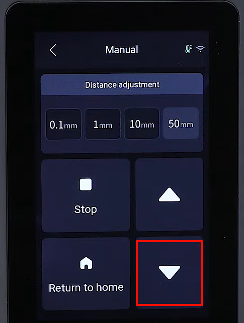
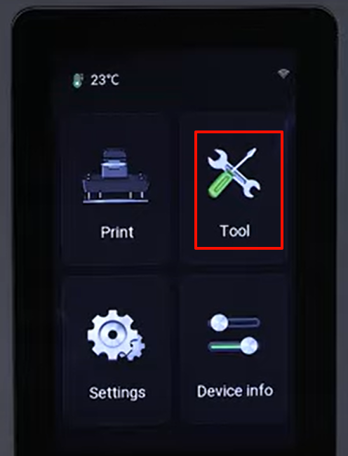
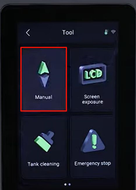
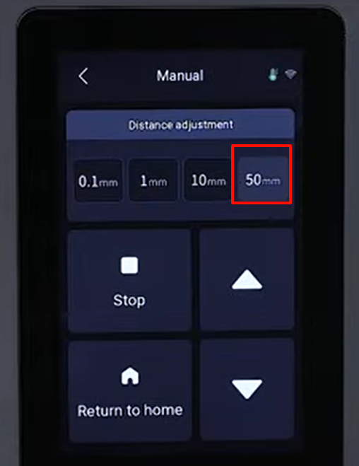
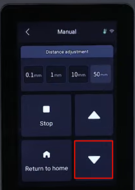
- Power on the printer. Tap "Tools - Manual - 50 mm" and lower down the Z-axis.
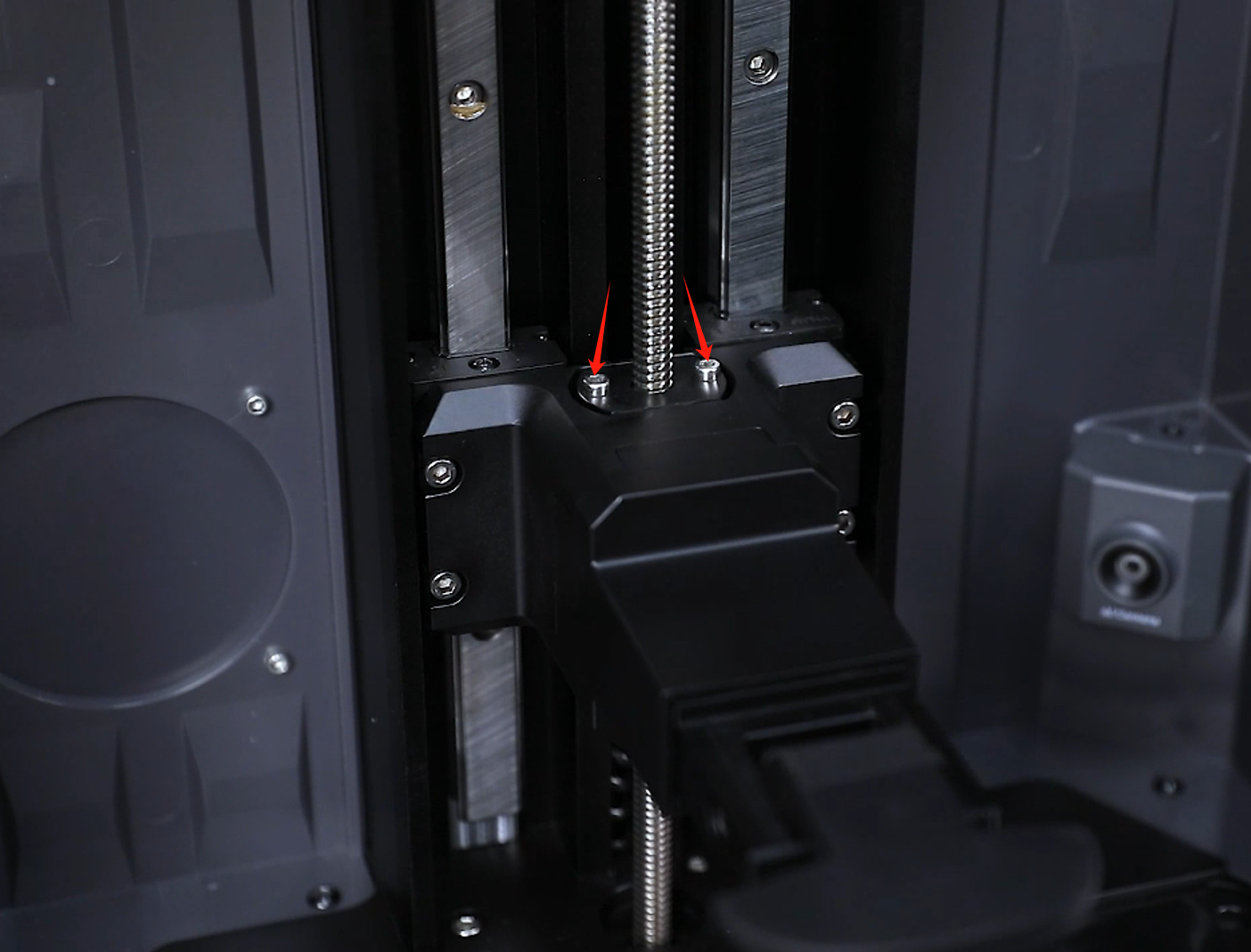
- After the Z-axis lowered to the bottom position, use a 2.5 mm Allen key to securely tighten the 2 screws holding the nut multiple times.
- Touch "Homing" on the touchscreen and the printer starts homing process. Lower down the Z-axis and the printer is ready for use after the axis lowers down normally.