¶ Tools and Materials
- A 2.0 mm Allen wrench
- A 2.5 mm Allen wrench
- A pair of diagonal pliers
- Labels or label ties

¶ Tutorial Video
¶ Instruction
¶ Remove the Old Thermistor of the Resin Tank
- Power off the printer and unplug the power cord.
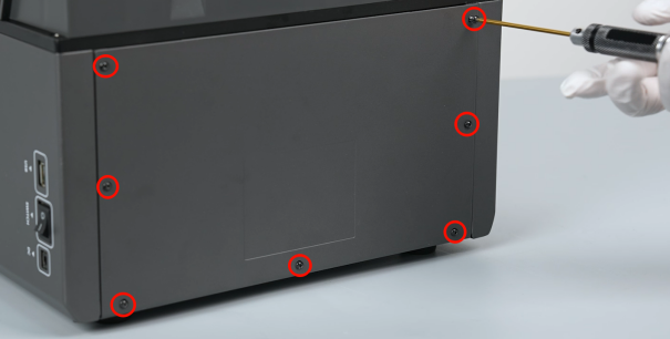
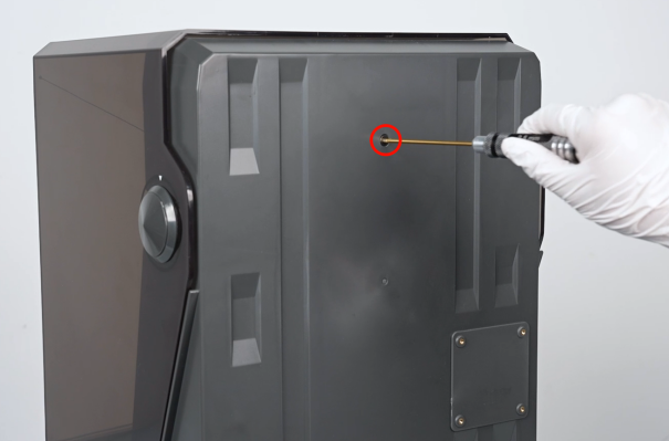
- Use a 2.0 mm Allen wrench to loosen the 7 screws securing the back cover of the printer, then remove the back cover.
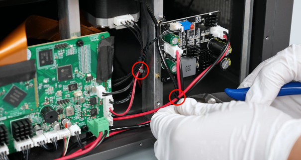
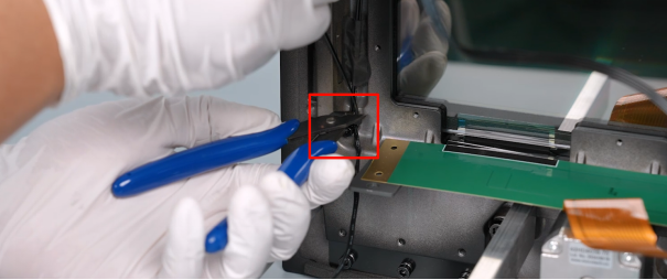
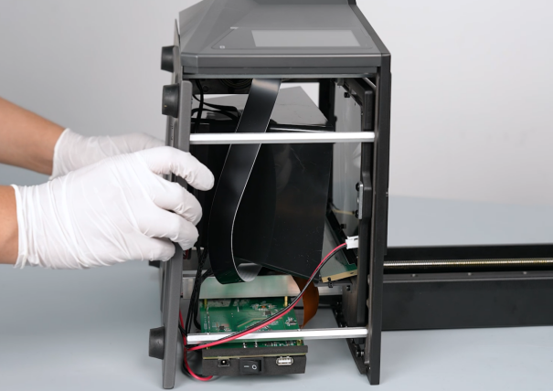
- Use a pair of diagonal pliers to cut off the label ties securing the ribbon cables. Mark the same size ribbon cables using the labels or label ties to correspond to the names of the ports on the motherboard.
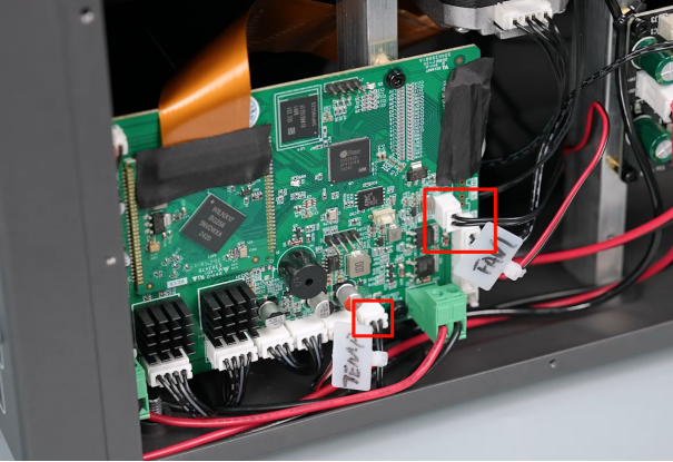
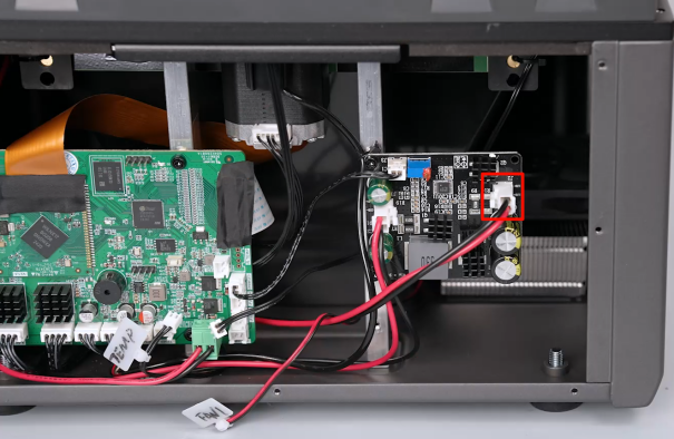
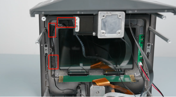
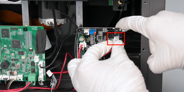
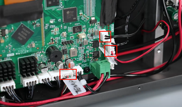
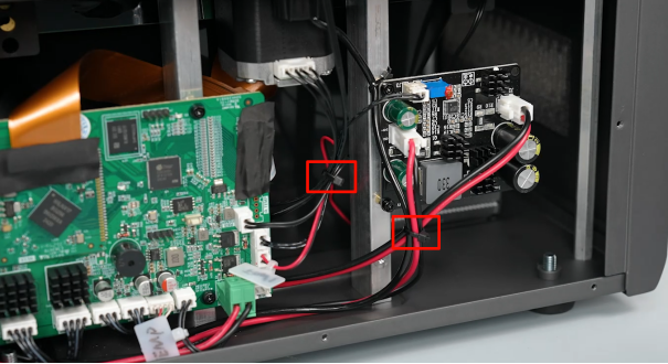
- Unplug the ribbon cables of the TEMP port (thermistor of the UV light), FAN1 port (cooling fan) and IR TEMP port (thermistor of the resin tank) on the motherboard. Unplug the ribbon cables of the J2 port (UV light) from the constant current board.
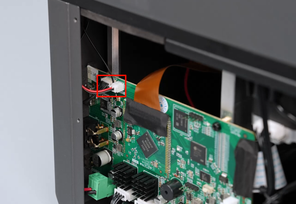
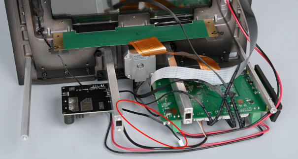
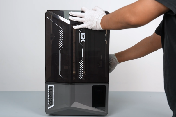
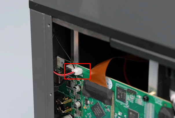
- Unplug the ribbon cables of the camera, illuminating light and the Wi-Fi port on the motherboard. Lift the top cover of the printer.
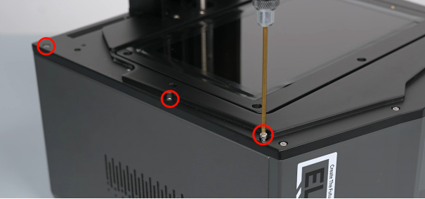
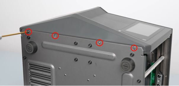
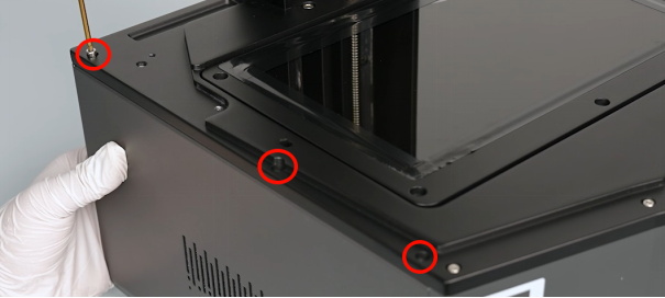
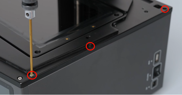
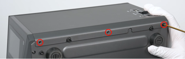
- Use a 2.5 mm Allen wrench to loosen the 6 screws underneath the top cover, then place the top cover back on.

- Use a 2.5 mm Allen wrench to loosen the screw securing the back side of the printer, then remove the top cover.
Note: Organize the 3 ribbon cables in the reserved holes at the right side.
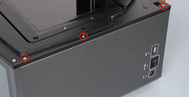
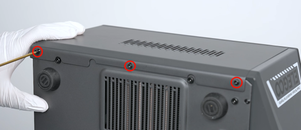
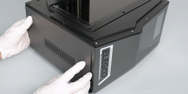
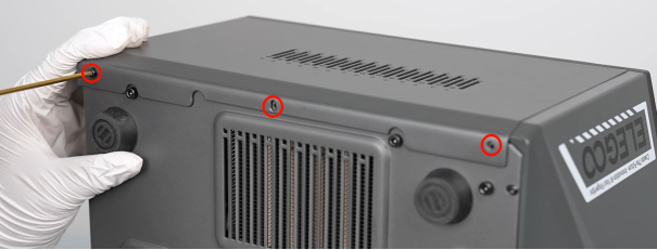
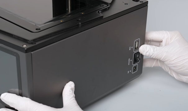
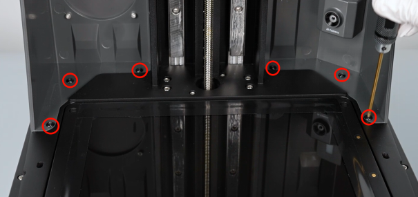
- Use a 2.5 mm Allen wrench to loosen the 3 screws securing the upper side and lower side of the printer's right cover, then remove the right cover.
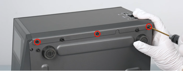
- Use a 2.5 mm Allen wrench to loosen the 3 screws securing the upper and lower sides of the printer's left cover, then remove the left cover.
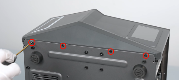
- Use a 2.0 mm Allen wrench to loosen the 4 screws underneath the front cover.
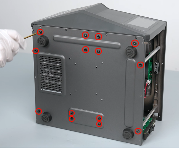
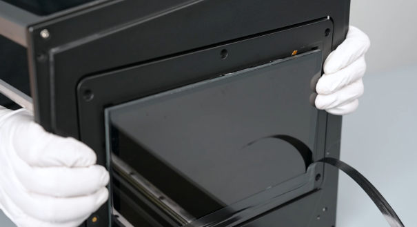
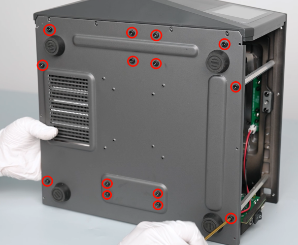
- Use a 3.0 mm Allen wrench to loosen the 14 screws securing the back cover of the printer, then remove the back cover assembly.
Note: Hold the back cover to prevent it from falling while loosening the last 2 screws.
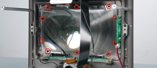
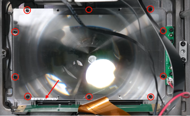
- Use a 2.5 mm Allen wrench to unscrew the 10 screws securing Fresnel lens, then remove the fans. It is recommended to place the Fresnel lens on clean A4 paper to prevent contamination.
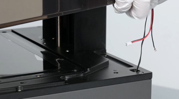
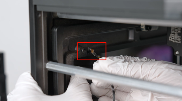
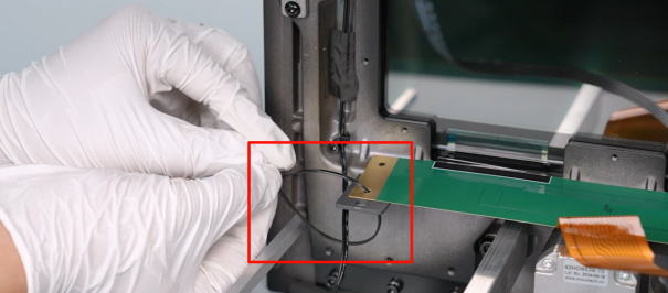
- Use a pair of diagonal pliers to cut off the cable ties securing the thermistor of the resin tank.
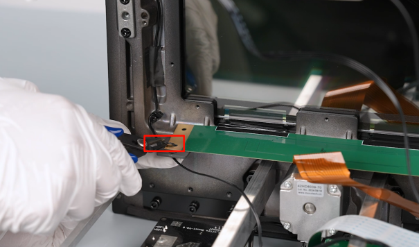
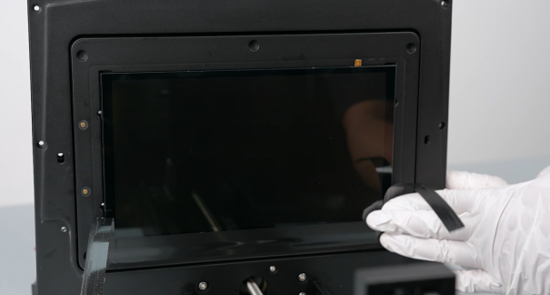
- Tidy up the ribbon cables of the thermistor of the resin tank, then remove the black tape securing the ribbon cables.
Note: Reserve the black tape for subsequent use.
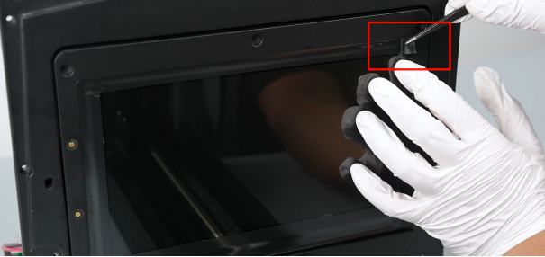
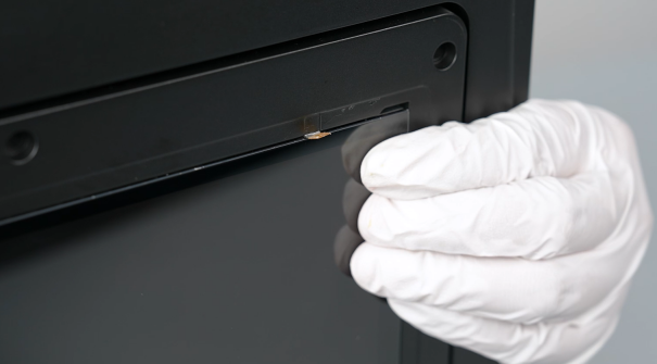
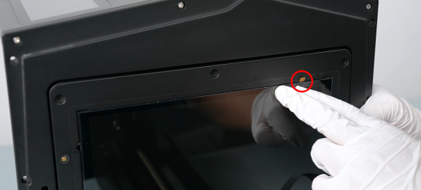
- Use a pair of tweezers to gently lift the corner of the black tape holding the LCD screen in place. Tear the 3 strips of black tape both at the front and two sides of the LCD screen.
Note: Reserve the black tape for subsequent use.
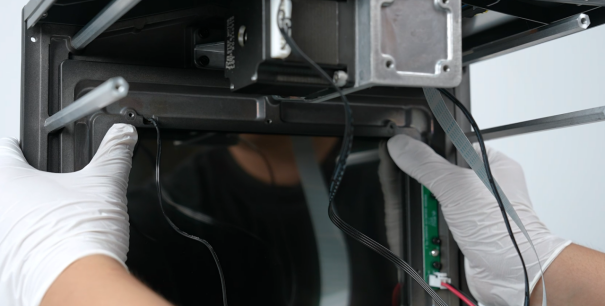
- Press the two corners of the LCD screen with both hands underneath the printer until the edges of the screen are raised.
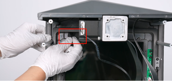
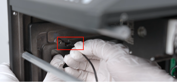
- Pull the old thermistor of the resin tank out underneath the printer.
¶ Install the New Thermistor of the Resin Tank
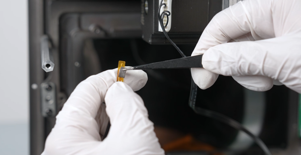
- Prepare the new thermistor of the resin tank. Apply double-sided tape in front of the thermistor.
- Push the LCD screen to open a gap. Put the thermistor of the resin tank in the installation position.
- Press around the LCD screen to adhere the screen to the installation position.
- Press to adhere the front of the thermistor.
- Adhere the black tape securing the LCD screen back to its original position.
- Tidy up the ribbon cables of the thermistor of the resin tank. Use black tape and cable ties to secure the ribbon cables of the thermistor of the resin tank.
- Tidy up ribbon cables of the thermistor of the resin tank from the ports to the motherboard.
- Put the Fresnel lens in the installation position by aligning it the the screw holes. Use a 2.5 mm Allen wrench to tighten the 10 screws securing Fresnel lens.
Note: The Fresnel lens has its fixed installation direction. Remember to record the direction.
- Remove the back cover assembly. Distinguish the direction of the bottom cover installation direction according to the position of the screw holes on the bottom cover. Put the bottom cover in the installation position by aligning it the the screw holes.
Note: Tidy up the ribbon cables to avoid being crushed during installation.
- Use a 3.0 mm Allen wrench to loosen the 14 screws securing the bottom cover. (Rotate the screws by three-quarters torque, then tighten the screws completely.)
- Use a 2.0 mm Allen wrench to tighten the 4 screws underneath the front cover.
- Prepare the left-side cover, then put it in the installation position by aligning it with the screw holes.
- Use a 2.5 mm Allen wrench to tighten the 3 screws securing the upper side and the lower side of the left-side cover of the printer.
- Prepare the right-side cover, then put it in the installation position by aligning it the the button holes and screw holes.
- Use a 2.5 mm Allen wrench to loosen the 3 screws underneath the top cover, then close the top cover.
- Remove the top cover of the printer. Put the top cover in the installation position by aligning it the the screw holes.
Note: Tidy up the 3 ribbon cables in the reserved holes at the right side.
- Use a 2.5 mm Allen wrench to tighten the 6 screws underneath the top cover.
- Use a 2.5 mm Allen wrench to tighten the 1 screws at the back of the top cover.

- Insert the ribbon cables of the UV light into the J2 port on the constant current board.
- Insert the ribbon cables into the ports on the motherboard according to the size of the port and the lable information. Use cable ties to secure the ribbon cables.
- Remove the back cover of the printer. Use a 2.0 mm Allen wrench to tighten the 7 screws securing the back cover of the printer.

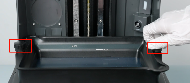
- Put the resin tank in the installation position by aligning it the the screw holes. Tighten the nuts at both sides of the resin tank.
- Power on the printer. The printer is ready for use after self-inspection.