¶ Tools and Materials
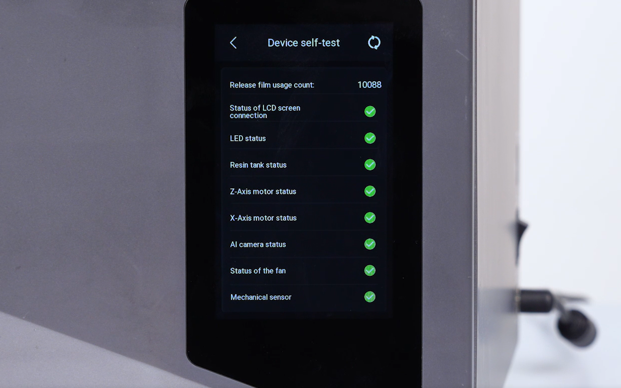
- A 2.0 mm Allen key
- A 2.5 mm Allen key
- A pair of pliers
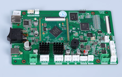
- A new motherboard
¶ Tutorial Video
¶ Instruction
¶ Power Off the Printer and Remove the Resin Tank
-
Turn the power switch OFF (symbol
"〇"). Unplug the power adapter cable. -
Lift the UV enclosure.
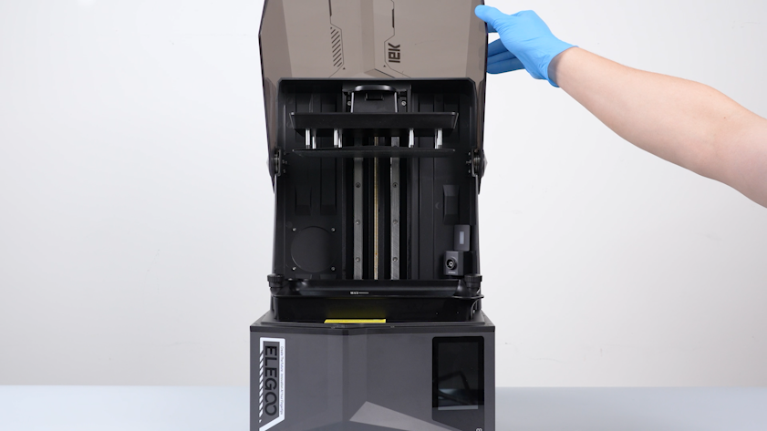
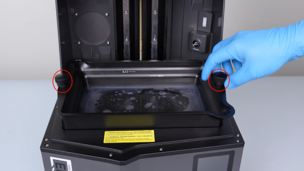
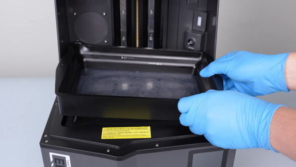
- Remove the two knob screws and remove the resin tank.
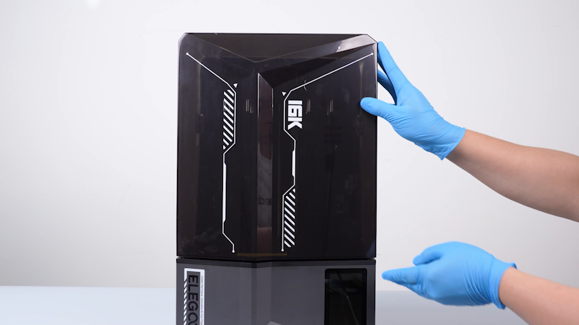
- Close the UV enclosure.
¶ Remove the Back Cover and Disconnect the Rear Cables
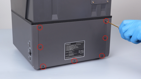
- Release and remove the seven screws securing the back cover with a 2.0 mm Allen key. Remove the back cover.
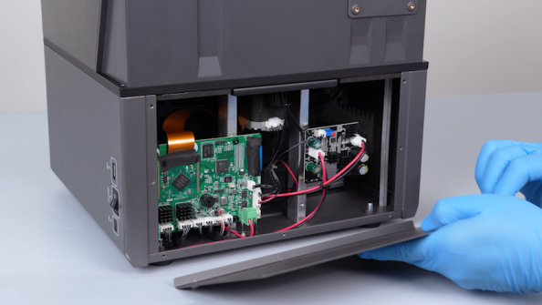
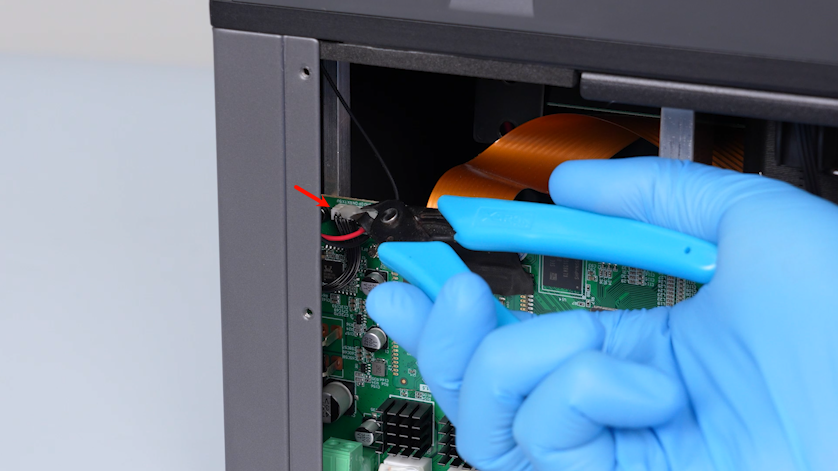
- Remove the hot-melt adhesive securing the cables in the top-left corner of the motherboard with a pair of pliers.
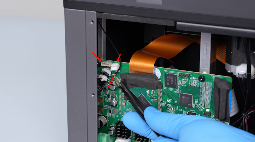
- Unplug the cables and the Wi-Fi antenna with a pair of tweezers.
¶ Remove the Back Cover Holder and UV Enclosure
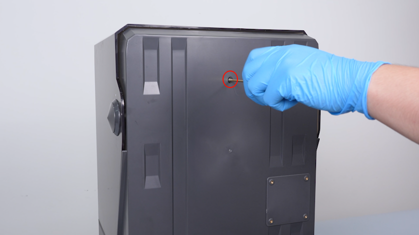
- Release and remove the screws securing the back cover holder with a 2.0 mm Allen key.
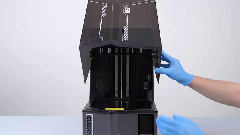
- Lift the UV enclosure.
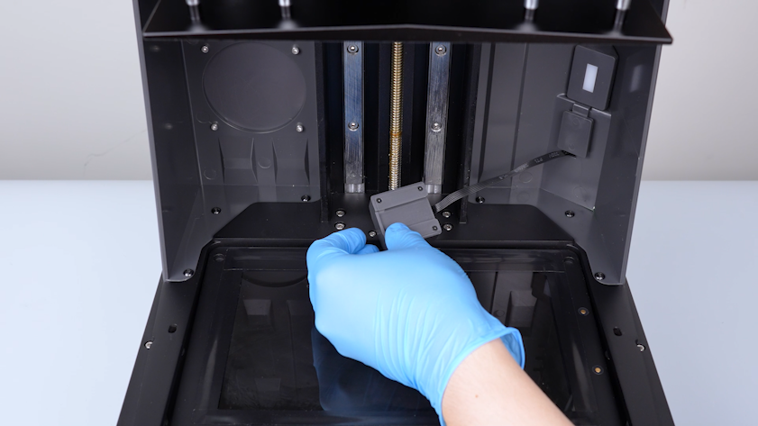
- Remove the camera and put it on the LCD screen temporarily.
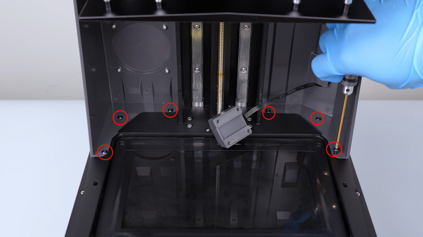
- Release and remove the six screws securing the back cover holder with a 2.5 mm Allen key.
Note: Hold the back cover holder when releasing the last screw.
- Put the camera back in its position.
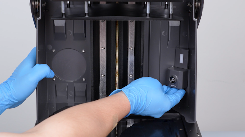
- Remove the UV enclosure and keep it at hand.
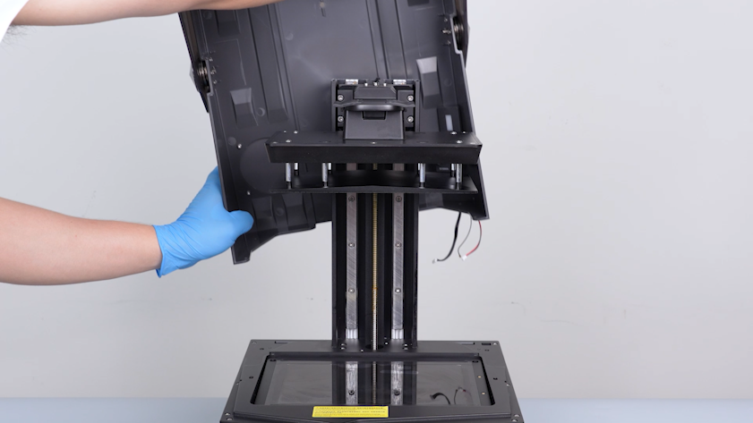
¶ Remove the Right-Side Cover
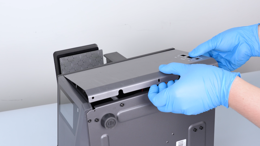
- Release and remove the three screws on the upper part of the right-side cover with a 2.5 mm Allen key.
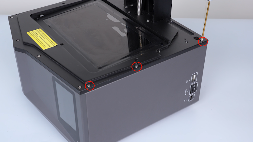
- Release and remove the three screws on the lower part of the right-side cover with a 2.5 mm Allen key.
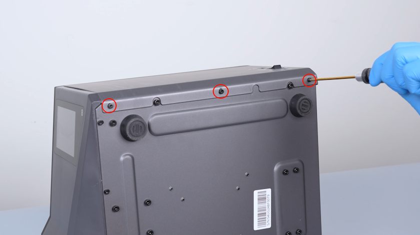
- Remove the right-side cover.
¶ Disconnect the Motherboard Cables
- Peel off the tape securing the touch screen ribbon cable. Lift the clip and unplug the touch screen ribbon cable.
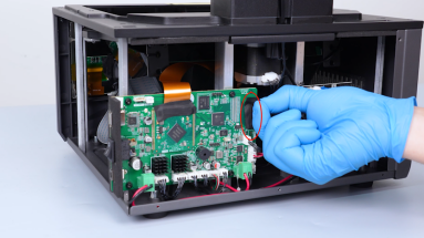
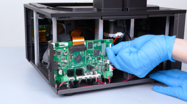
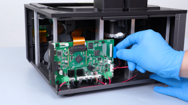
- Peel off the tape securing the LCD screen ribbon cable. Lift the clip and remove the LCD screen ribbon cable.
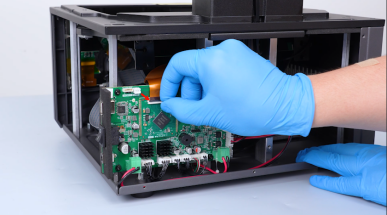
- Secure the cables with cable ties and mark the cables.
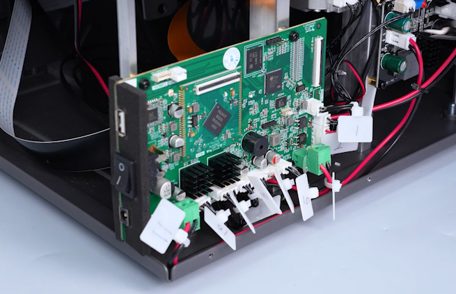
- Remove the hot-melt adhesive with a pair of pliers and remove the cables.
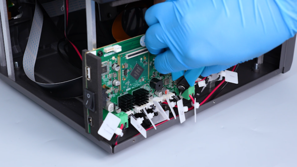
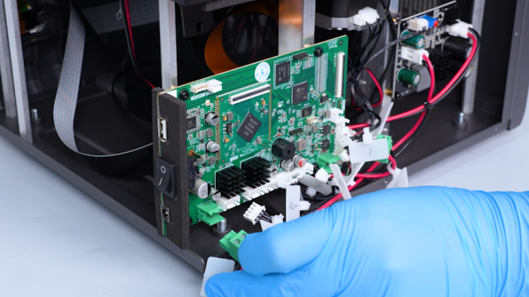
¶ Remove the Old Motherboard
- Release and remove the four screws securing the motherboard with a 2.5 mm Allen key.
Note: Hold the motherboard when releasing the last screw.
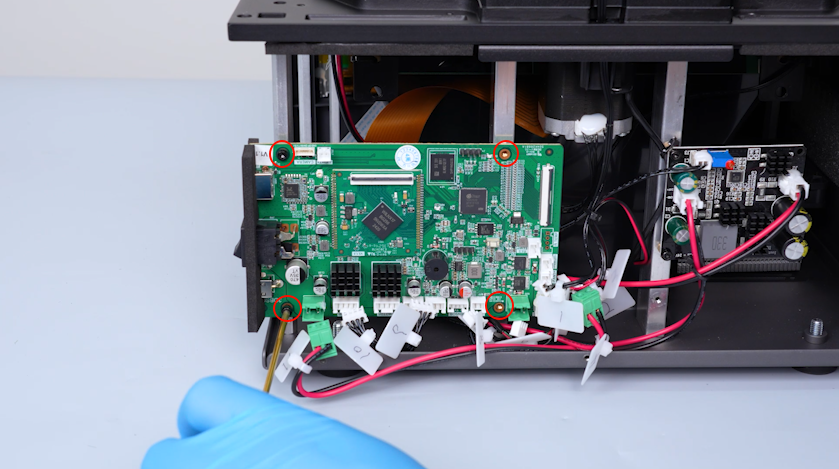
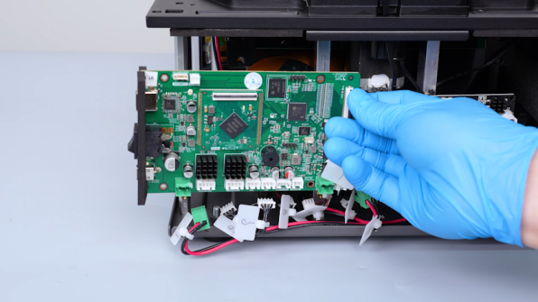
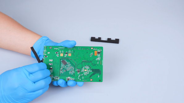
- Remove the old motherboard. Remove the shading plates from the sides of the motherboard.
¶ Attach the Shading Plates to the New Motherboard
-
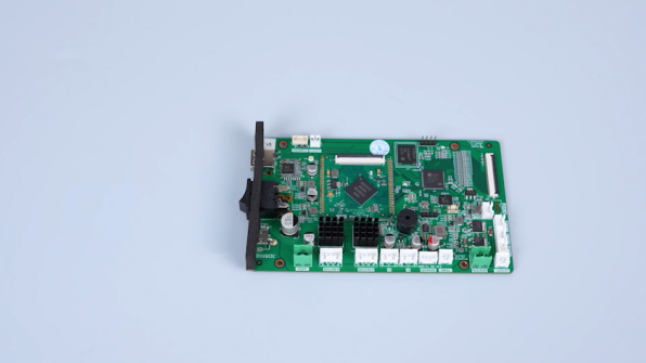
Get the new motherboard and the shading plates attached with double-sided tape.
-
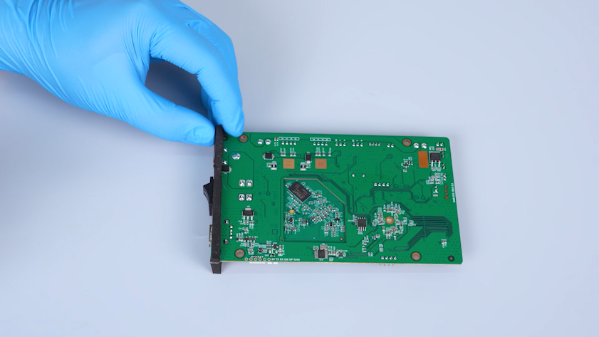
Peel off the protective paper from the double-sided tape. Attach the shading plate to its position on the left side of the motherboard.
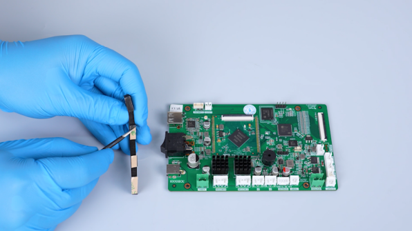
- Attach the other shading plate to the opposite side in the same way.
¶ Install the New Motherboard and Reconnect the Cables
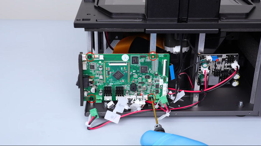
- Put the motherboard in the installation position. Tighten the four screws securing the motherboard.
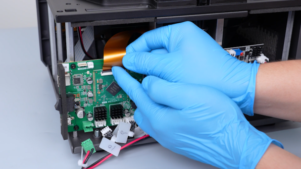
- Lift the clip. Plug in the LCD screen ribbon cable. Press the clip and secure the LCD screen ribbon cable with tape.
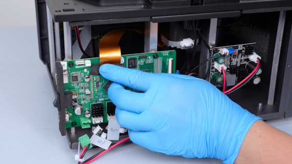
- Lift the clip. Plug in the touch screen ribbon cable. Press the clip and secure the touch screen ribbon cable with tape.
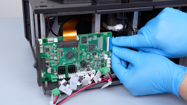
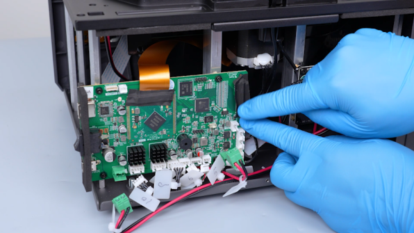
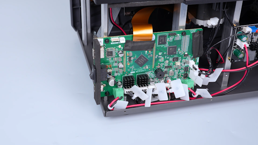
- Plug in the cables.
¶ Reinstall the Right-Side Cover and UV Enclosure
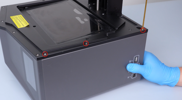
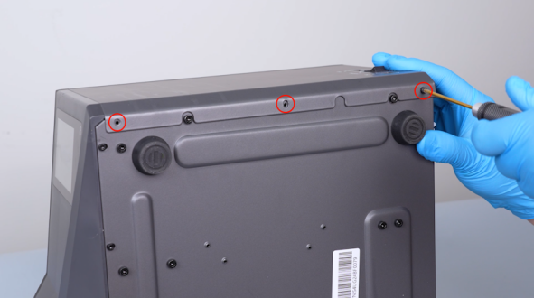
- Put the right-side cover in the installation position. Tighten the six screws on the upper and lower parts of the cover.
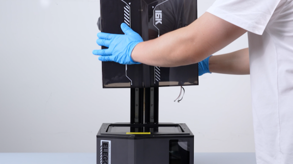
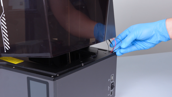
- Put the UV enclosure in the installation position. Pass the cables through the right-side hole.
- Close the UV enclosure.
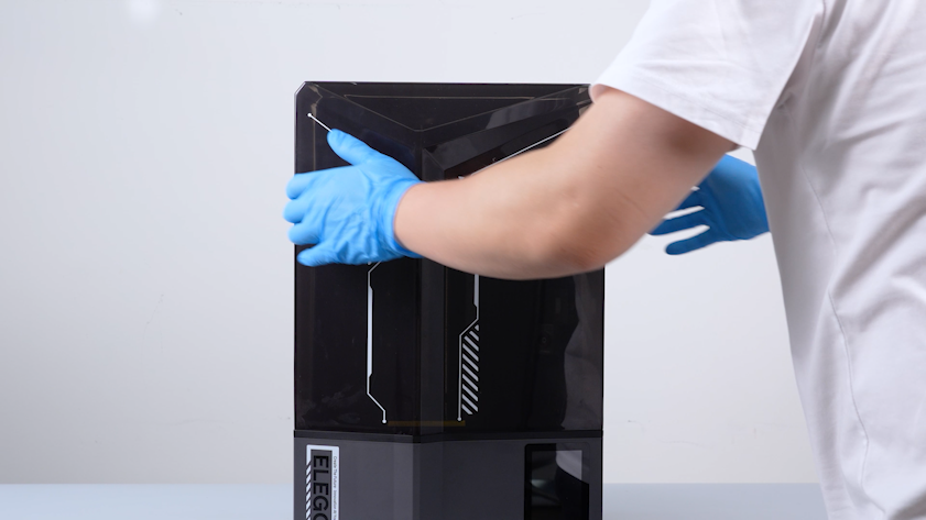
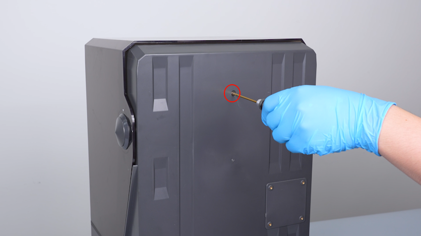
- Tighten the screw securing the back cover holder.
¶ Reconnect the Rear Cables and Reinstall the Back Cover
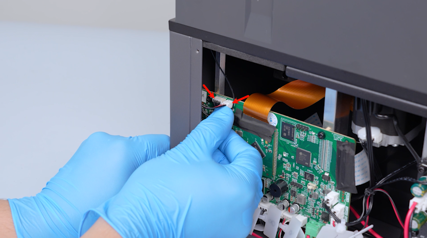
- Clamp the Wi-Fi antenna with a pair of tweezers. Plug in the Wi-Fi antenna.
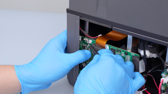
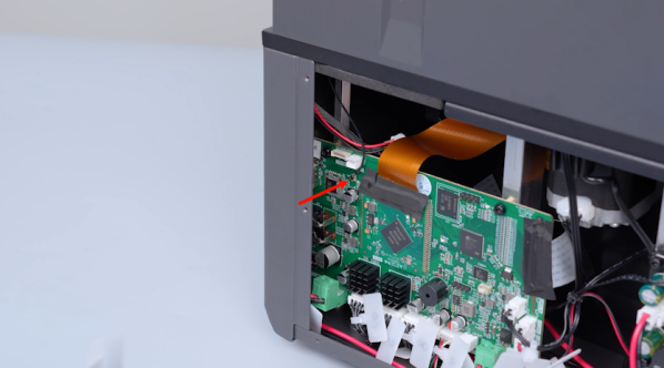
- Plug in the camera cable and the LED cable.
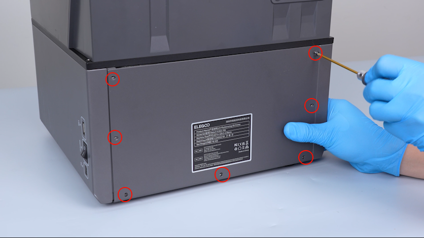
- Put the back cover in the installation position. Tighten the seven screws.
¶ Secure the Back Cover Holder
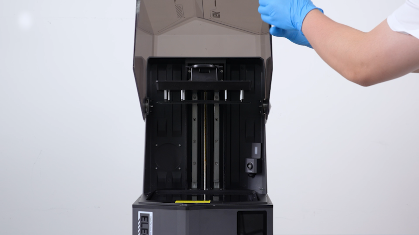
- Lift the UV enclosure.
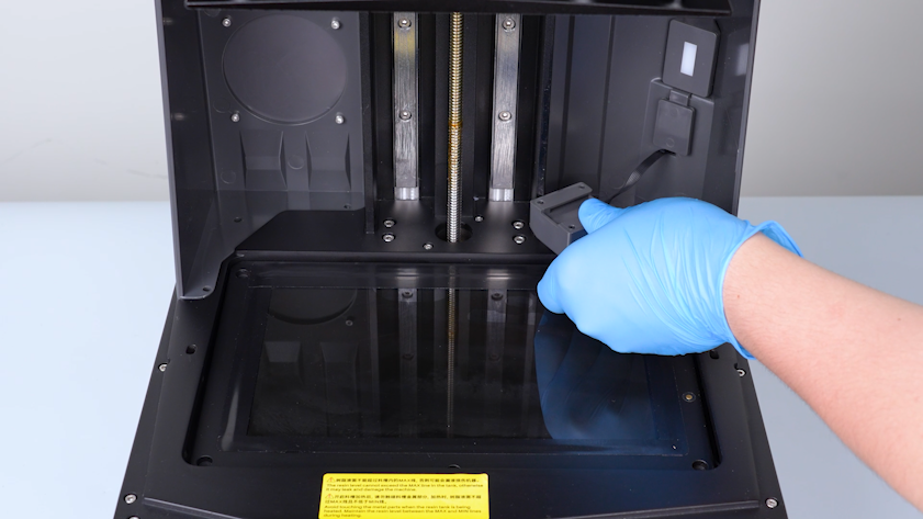
- Remove the camera and put it on the LCD screen temporarily.
- Tighten the screw securing the back cover holder in the middle.
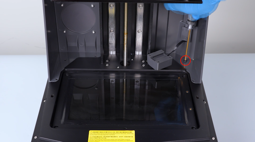
- Tighten the other five screws.
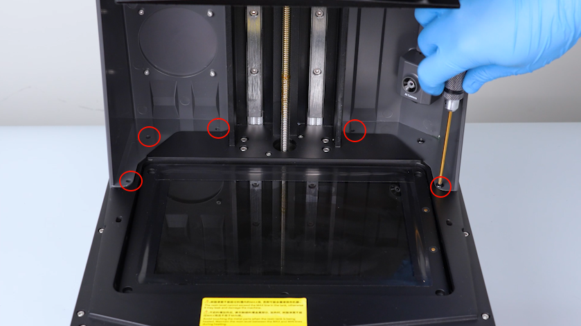
¶ Reinstall the Resin Tank
- Get the resin tank and put it in the installation position.
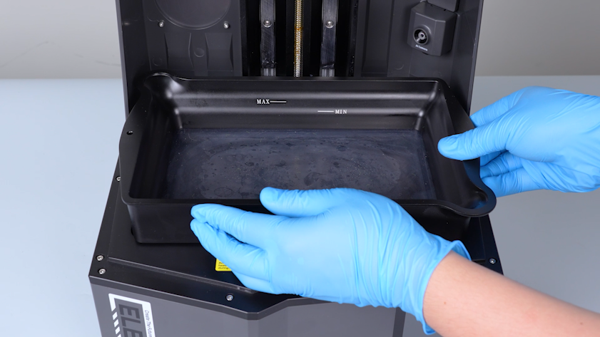
- Tighten the two knob screws.
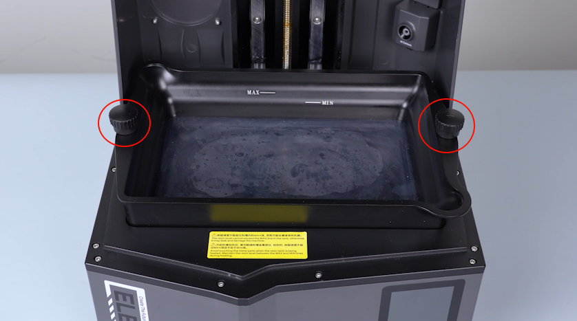
- Close the UV enclosure.
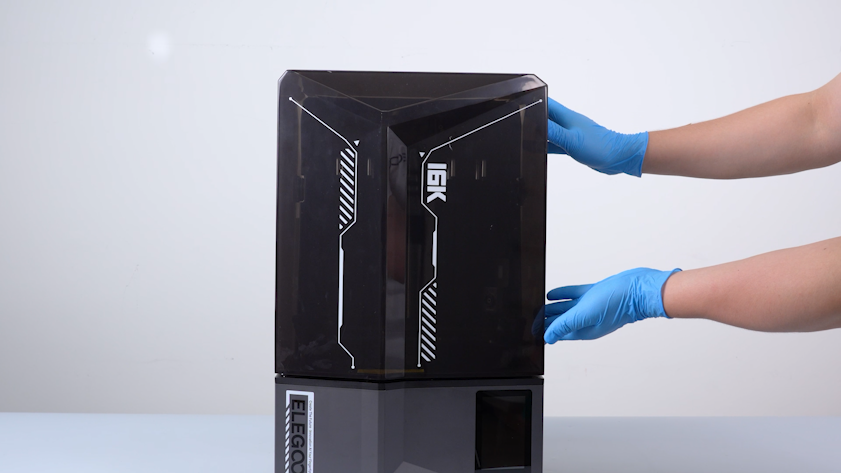
¶ Power On the Printer and Run the Self-Check
-
Plug in the power adapter cable. Turn the power switch ON (symbol
"|"). -
The printer is ready for use after the self-check.