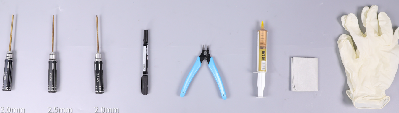
¶ Tools and Materials
- 3.0mm Allen key x 1
- 2.5mm Allen key x 1
- Marker pen
- A pair of diagonal pliers
- Thermal Paste
- Dust-free cloth
- Gloves
¶ Tutorial Video
¶ Instruction
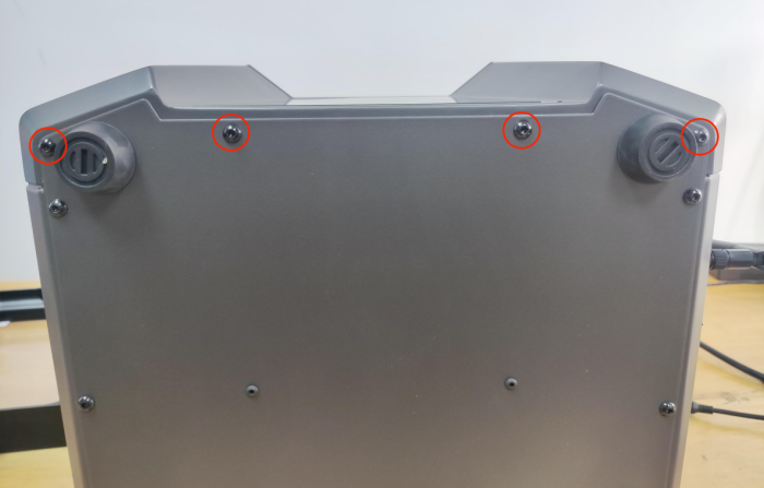
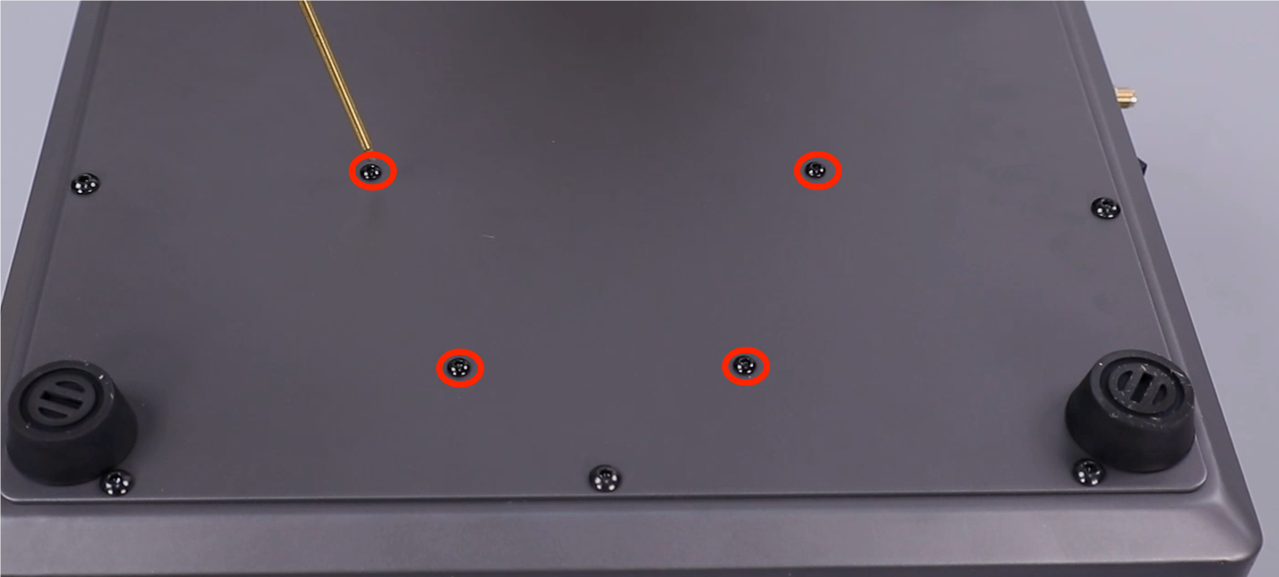
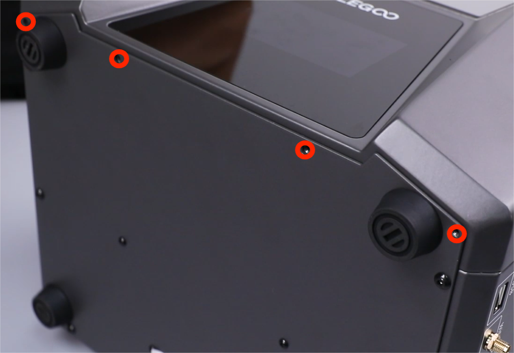
- Using a 2.5 mm Allen key, loosen the four screws securing the bottom cover.
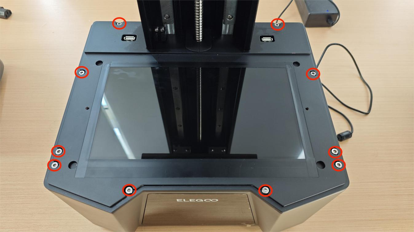
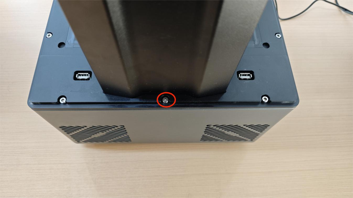
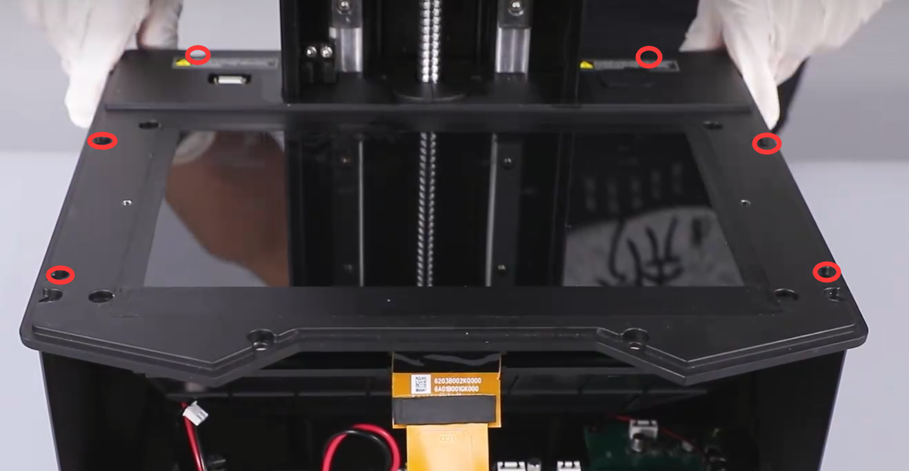
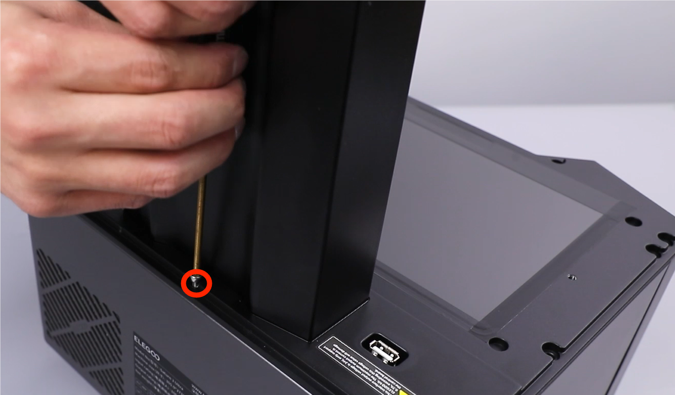
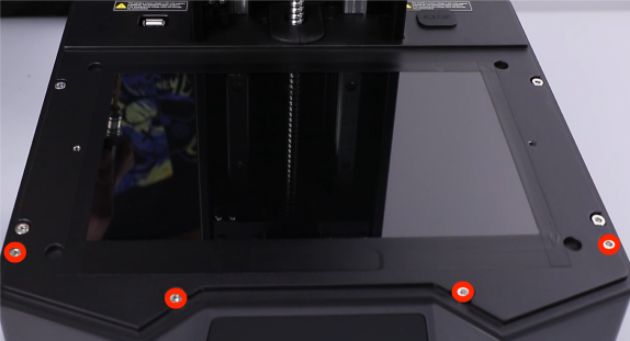
- Using a 3.0mm Allen key, loosen the eleven screws on the surface of the middle housing. One screw is fixed on the back side of the Z axis. After removing the middle housing, lay the middle housing flat.
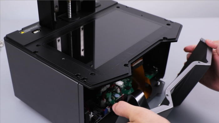
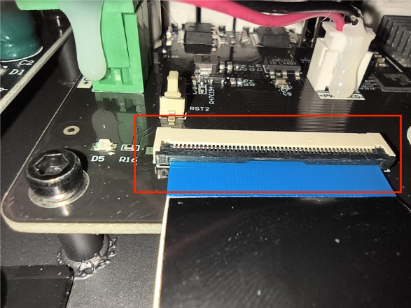
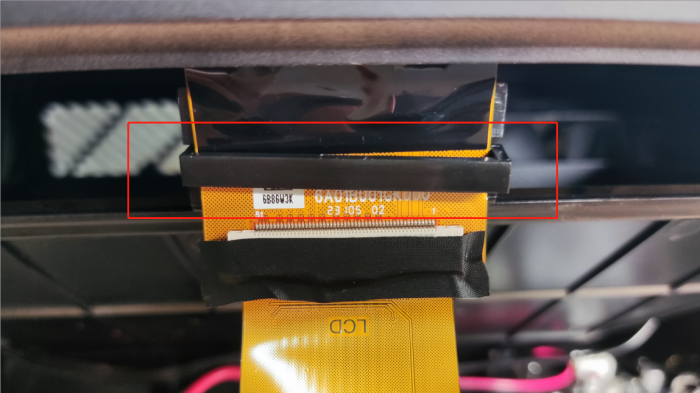
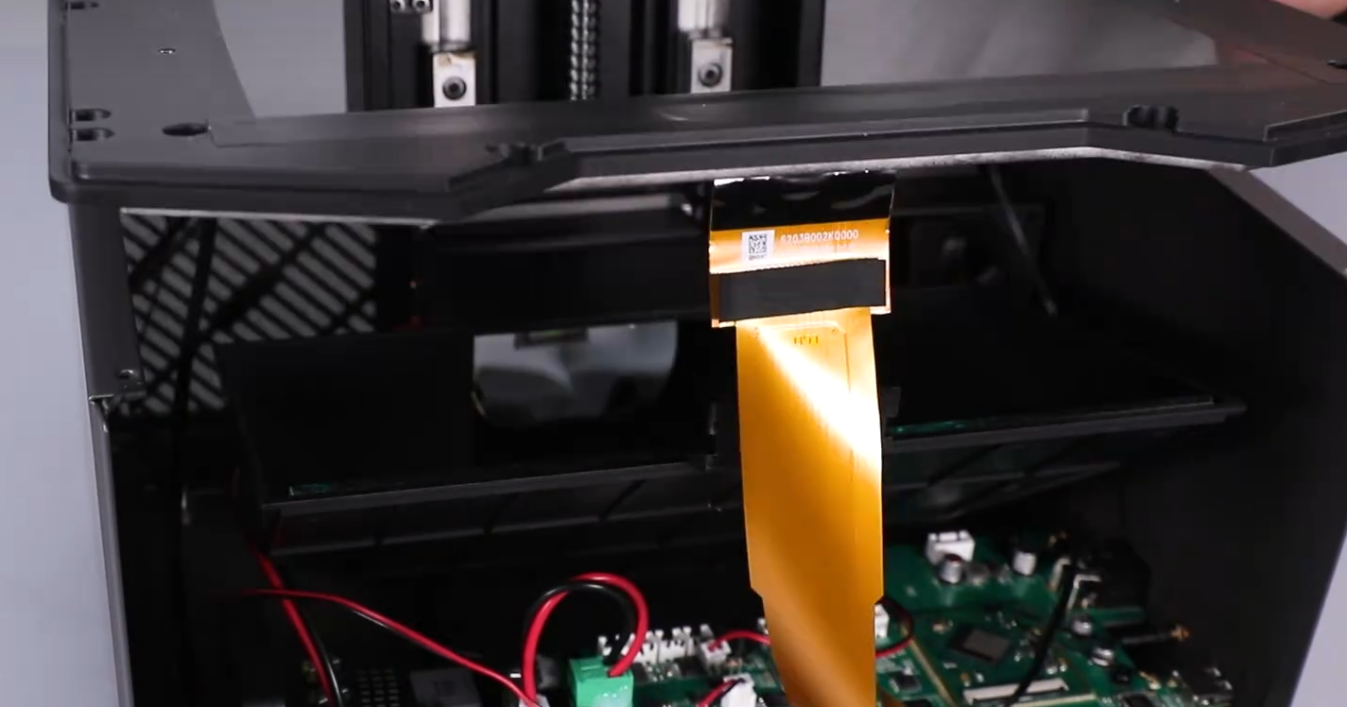
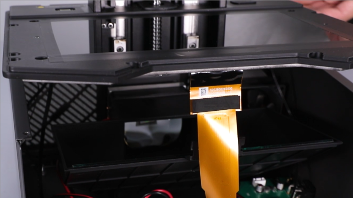
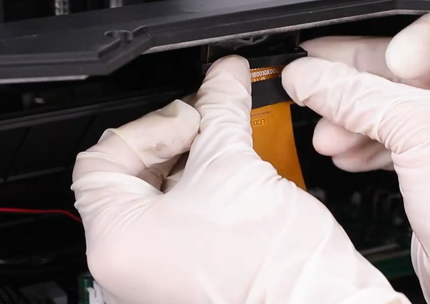
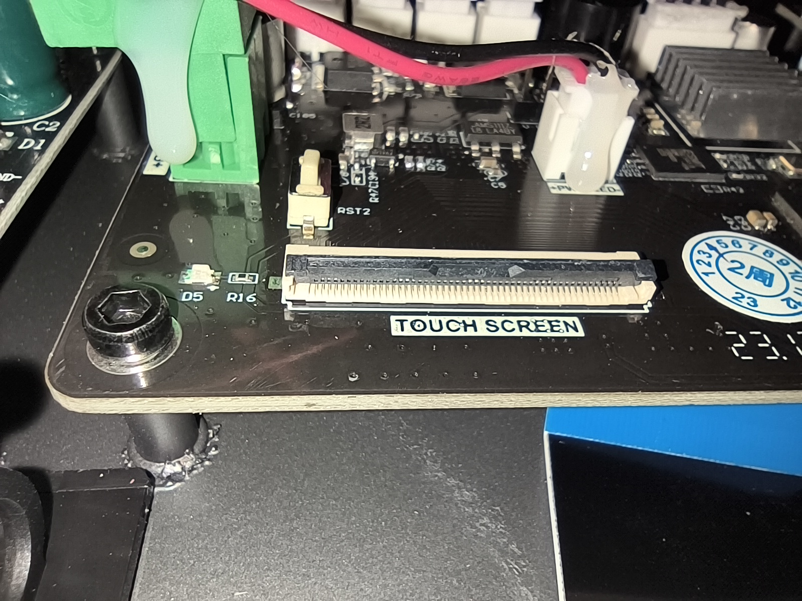
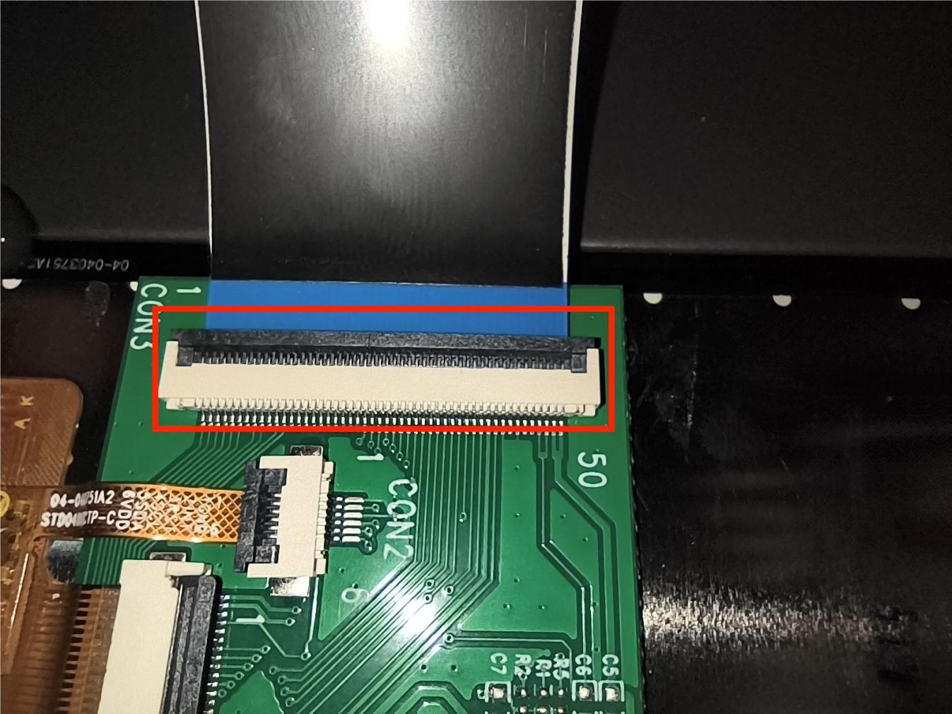
- Peel off the tape securing the ribbon cables of the LCD screen and the touchscreen. Lift the covers securing the bases of the LCD screen and the touchscreen. Remove the ribbon cables of the LCD screen and the touchscreen.
Ribbon cable of the LCD screen
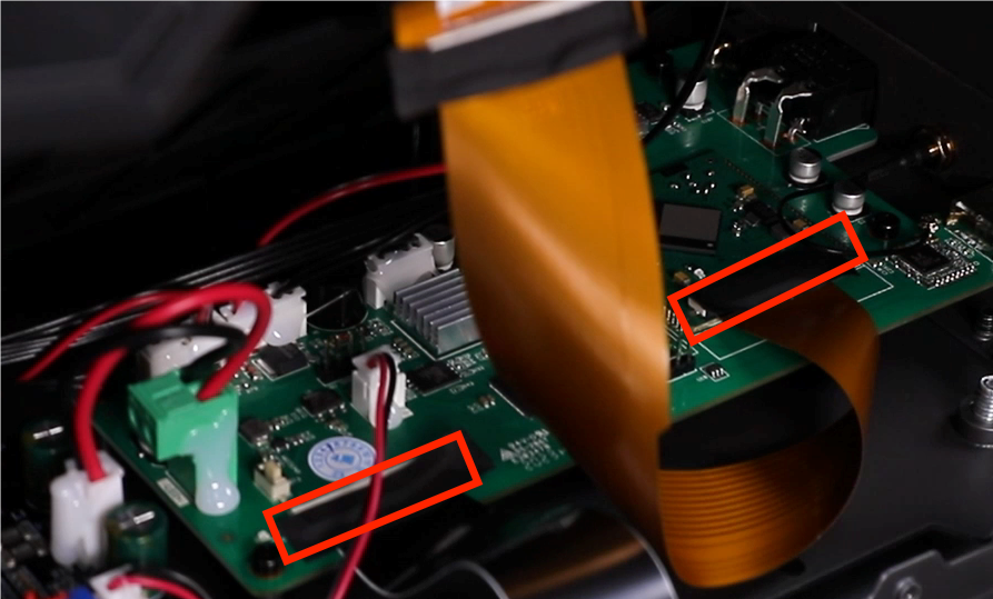


Ribbon cable of the touchscreen

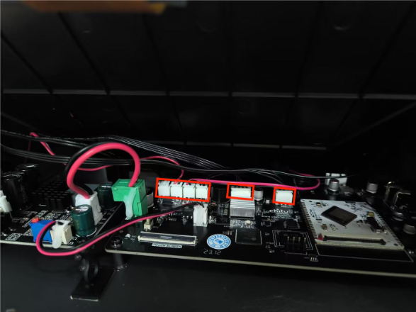
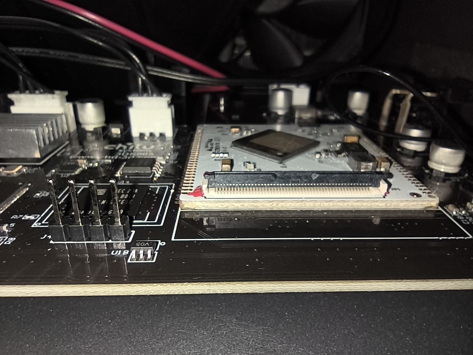
- Mark the connector of the connection cable of the motherboard (photos can be taken for reference) to facilitate subsequent installation and prevent plugging into the wrong ports. Remove sequentially the limit switch cable, the two USB connection wires, the connection cable of the cooling fan and the motor cable.
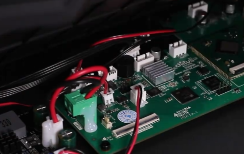
- Remove the cable clip from the right side.
- Remove the middle housing.
(Note: Remove the middle housing carefully to prevent the connection wires from breaking.)
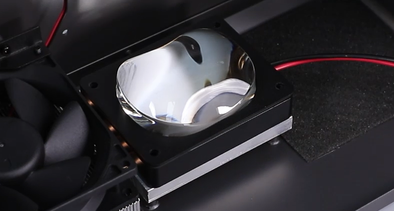
- Using a 2.0mm Allen key, loosen the four screws securing the lens shade on the bottom cover. Remove the lens shade.

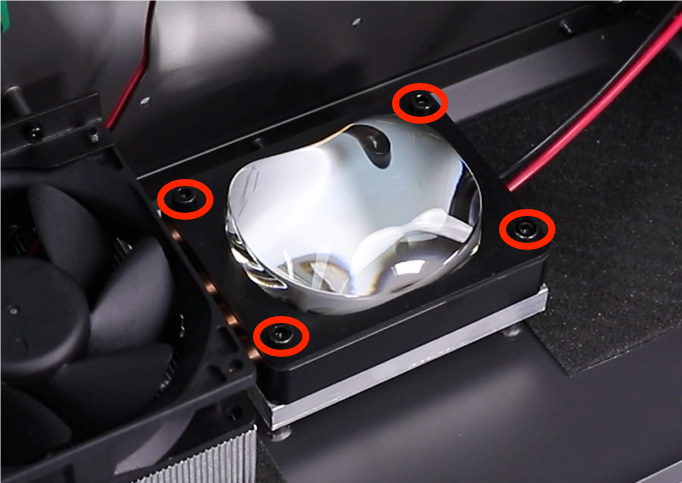
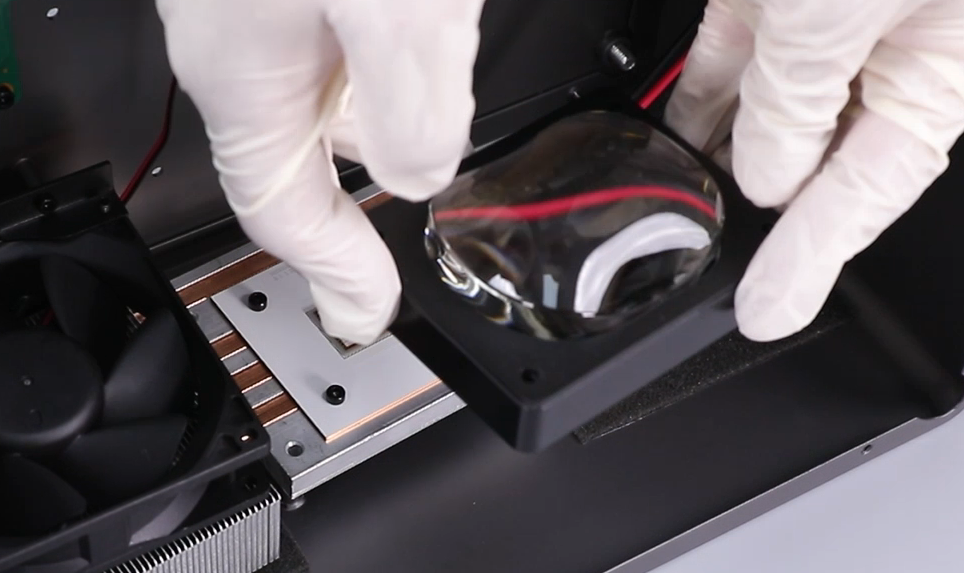
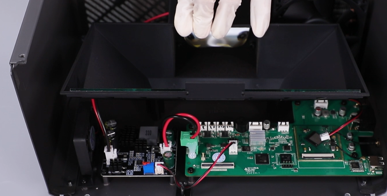
- Using a 2.5 mm Allen key, loosen the four screws securing the lens. Remove the lens with a pair of gloves.
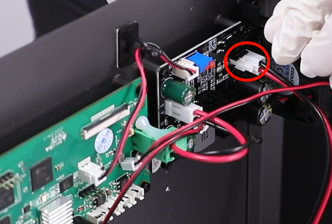
- Unplug the connection wire of the UV light board. Remove the UV light assembly.
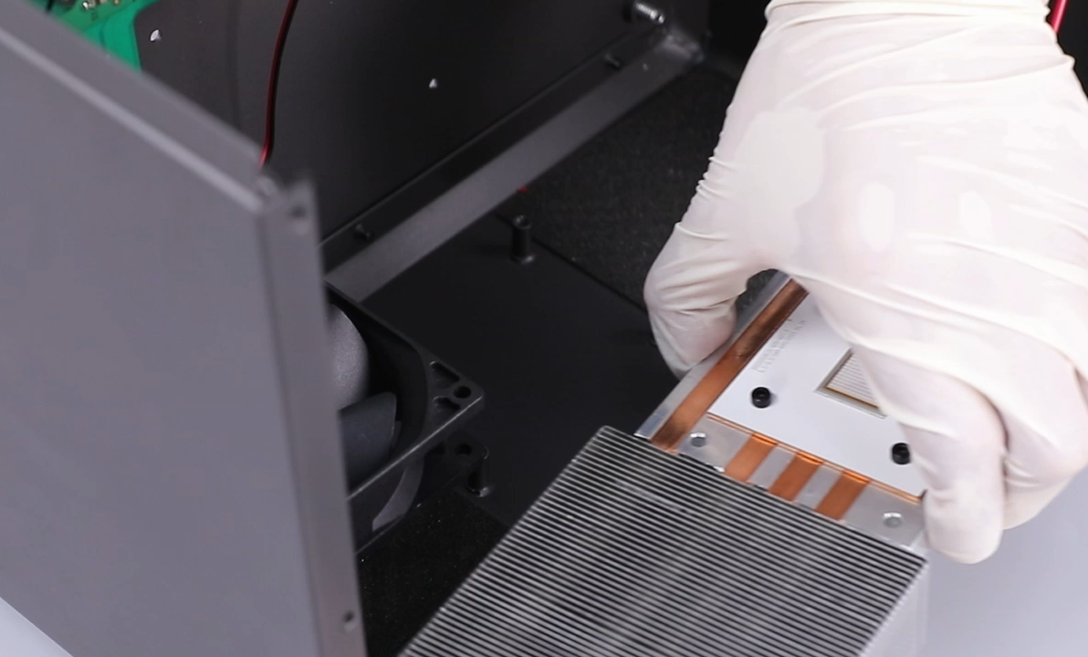
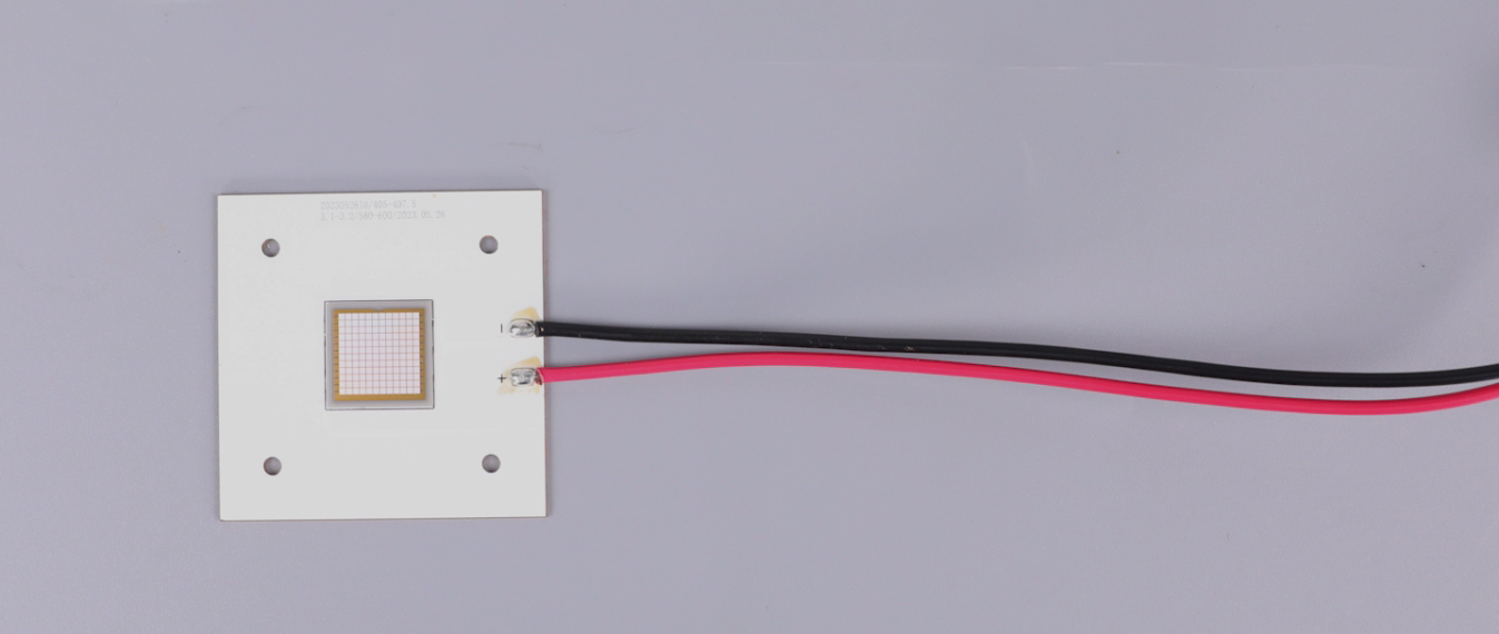
- Using a 2.5 mm Allen key, loosen the four screws securing the UV light and remove the old UV light.
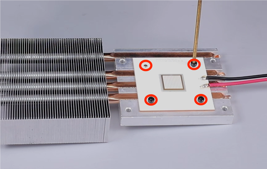
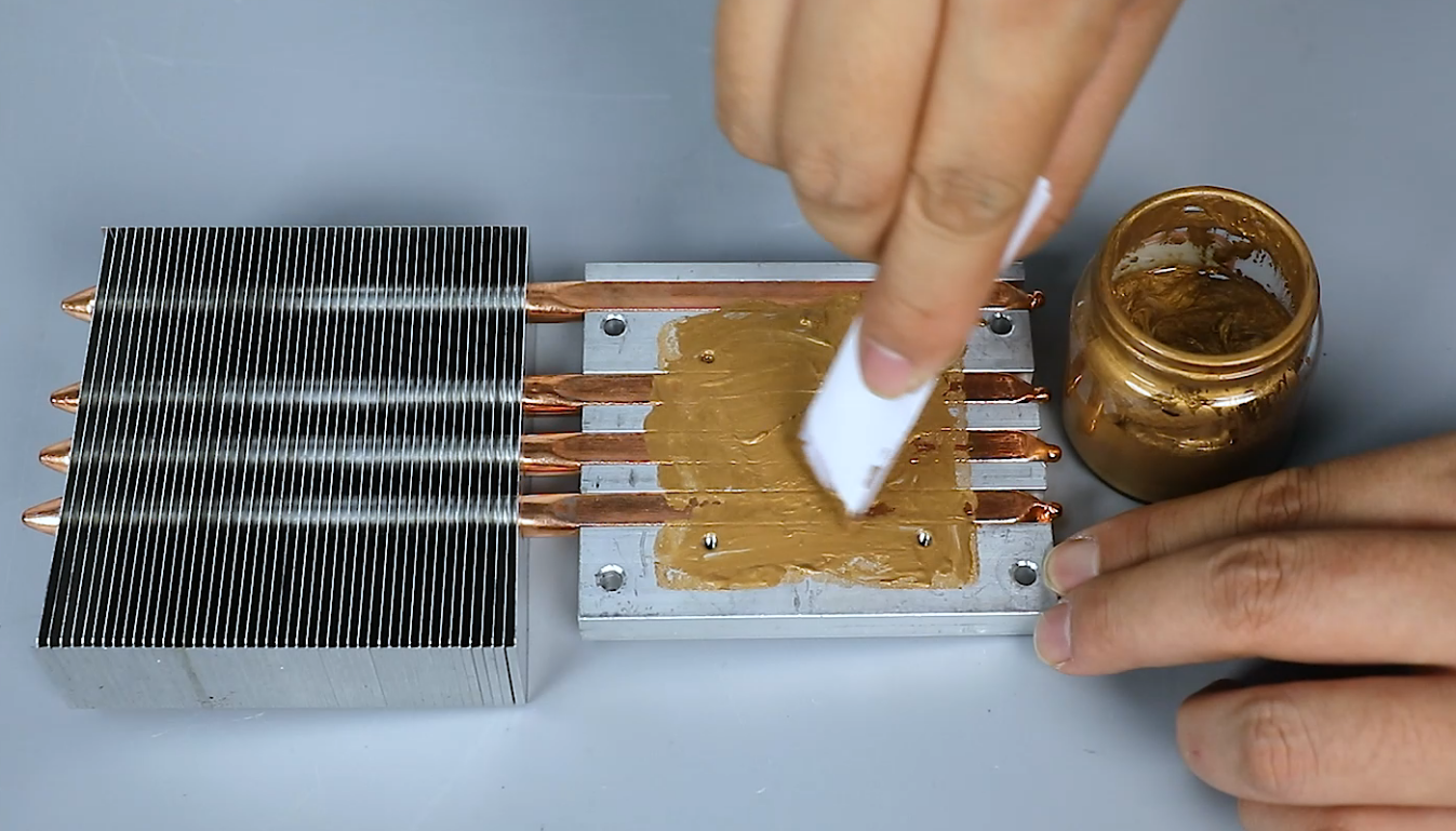
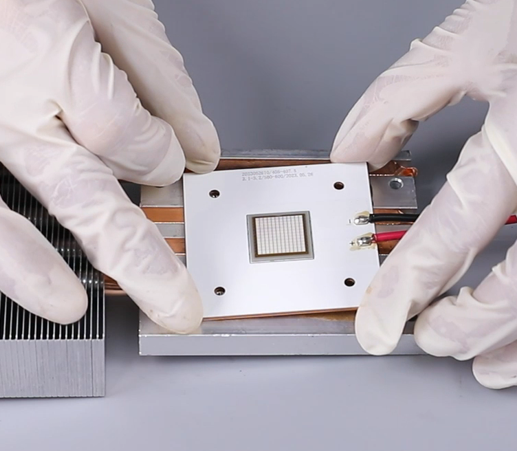
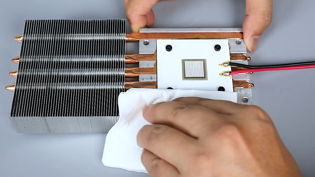
- Prepare the new UV light board. Apply the thermal grease to over the heatsink.
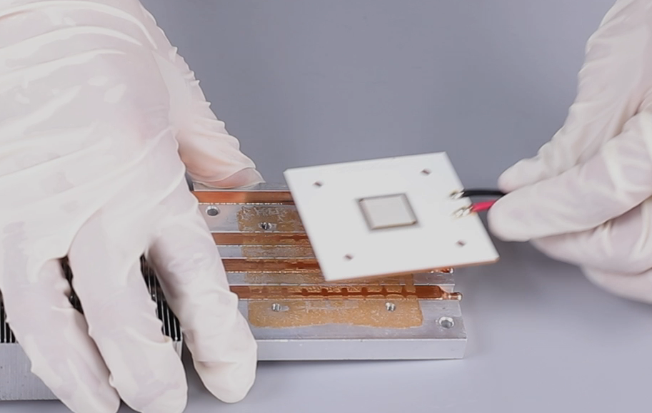
- Align the UV light board with the screw holes and install it in the installation position. Using a 2.5 mm Allen key, tighten the four screws securing the UV light board.
(Wipe away any excess thermal grease around the UV light with a tissue and avoid contaminating the light.)

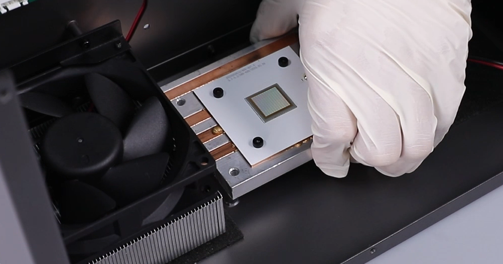
- Align the UV light assembly with the screw holes and install it in the installation position. Using a 2.5 mm Allen key, tighten the four screws securing the UV light assembly.

- Align the UV light board with the screw holes and install it in the installation position. Using a 2.0 mm Allen key, tighten the four screws securing the UV light board.
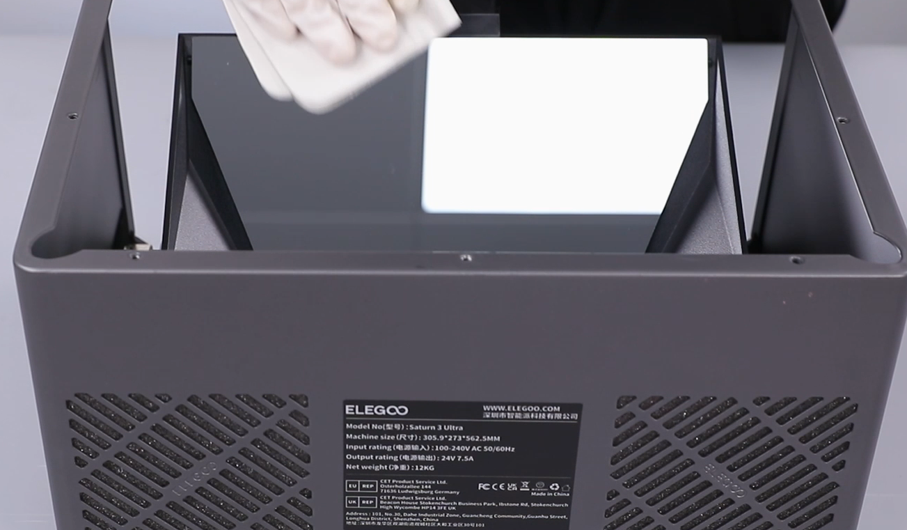
- Wipe the reflective mirror surface with a lint-free cloth to prevent fingerprints and dirt.
- Install the printer's middle housing. Do not press any cable. Using a 2.5mm Allen key, tighten the seven screws on the back side of the middle housing. Reinstall the lead screw motor and screw it.
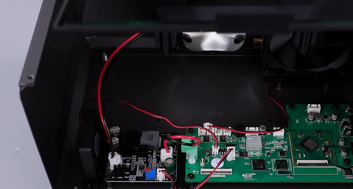
- According to the label information, insert the two cooling fan cables, two connection wires of the air purifier, limit switch connection wire and the lead screw connection wire.

- Install the cable clip.
- Install the LCD screen ribbon cable and touchscreen ribbon cable into their original positions in sequence, fasten the cable mounting brackets, and secure them with tape.
Ribbon cable of the LCD screen
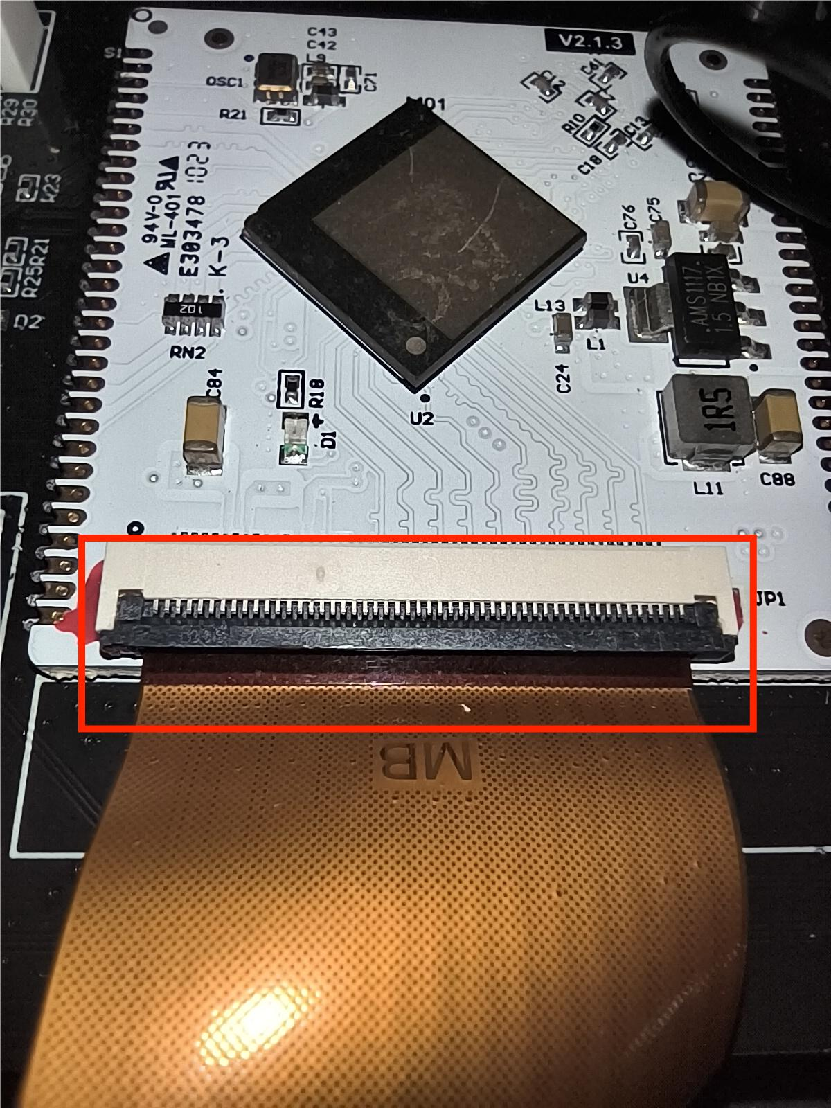
Ribbon cable of the touchscreen

- Align thefront board with the screw holes and install it in the installation position. Using a 3.0 mm Allen key, tighten the four screws securing the middle housing.
- Using a 2.5 m Allen key, tighten the four screws.
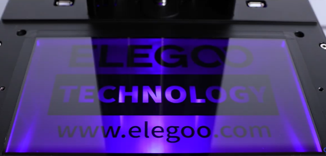
- Power on the printer and make sure that the UV llight works normally.
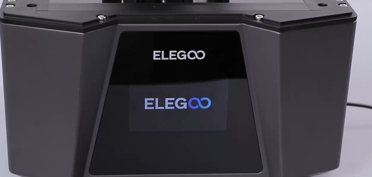
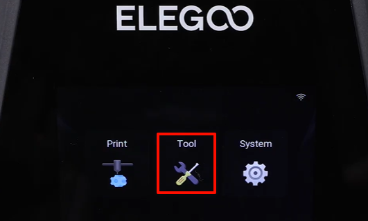
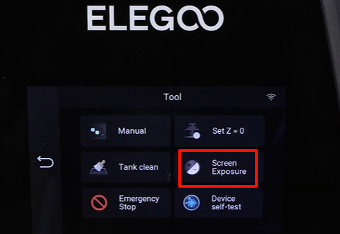
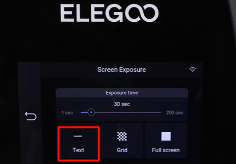
- Power on the printer. On the touchscreen, select Tool - Screen Exposure - ELEGOO. The printer is ready for use if the screen exposure works normally.