¶ Tools and Materials
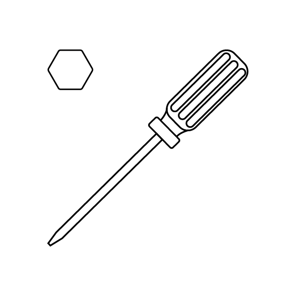
- 2.0 mm Allen key x 1
- 2.5 mm Allen key x 1
- A4 paper
¶ Tutorial Video
¶ Precautions
This method is employed to determine whether the machine can operate normally when the power switch PCB board is out of connection.
Note: Do not use the printer continuously with this method to avoid malfunction.
¶ Instruction
-
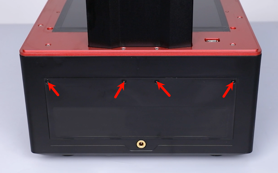
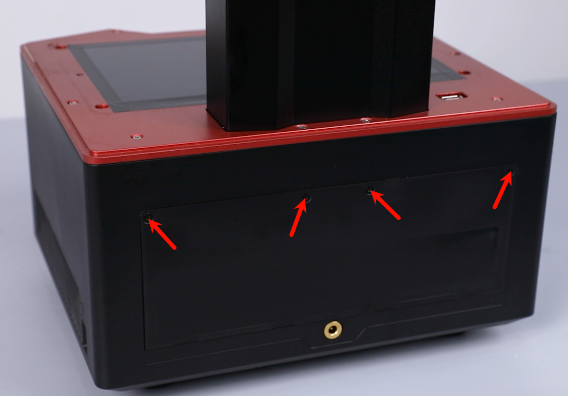
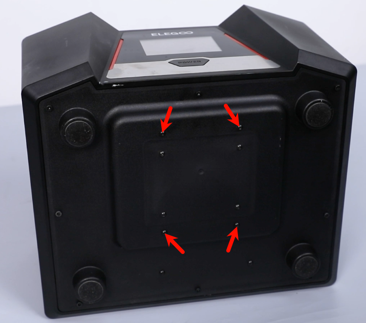
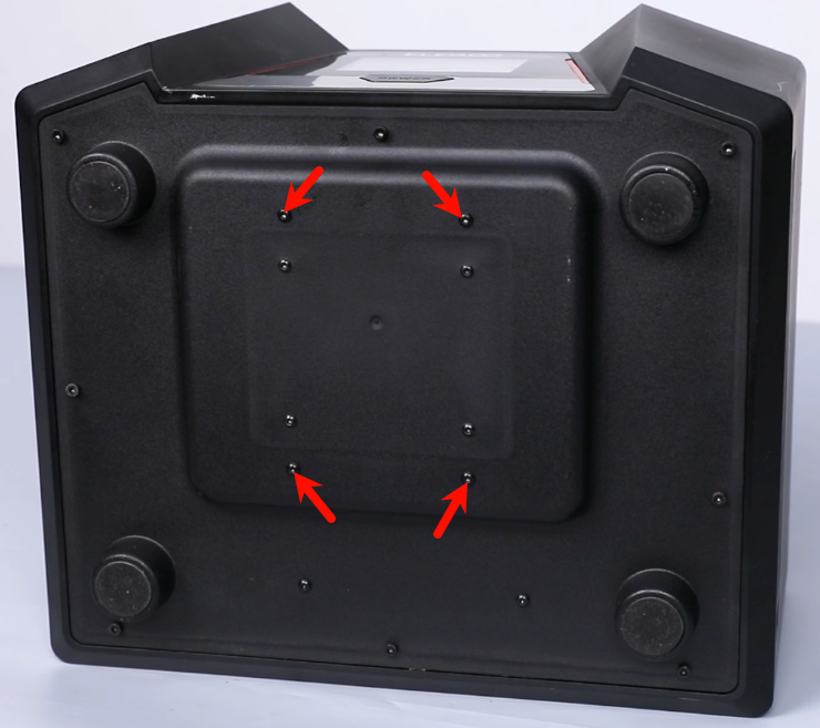
Loosen the 4 screws securing the back cover of the printer with a 2.0 mm Allen key. Remove the back cover.
-
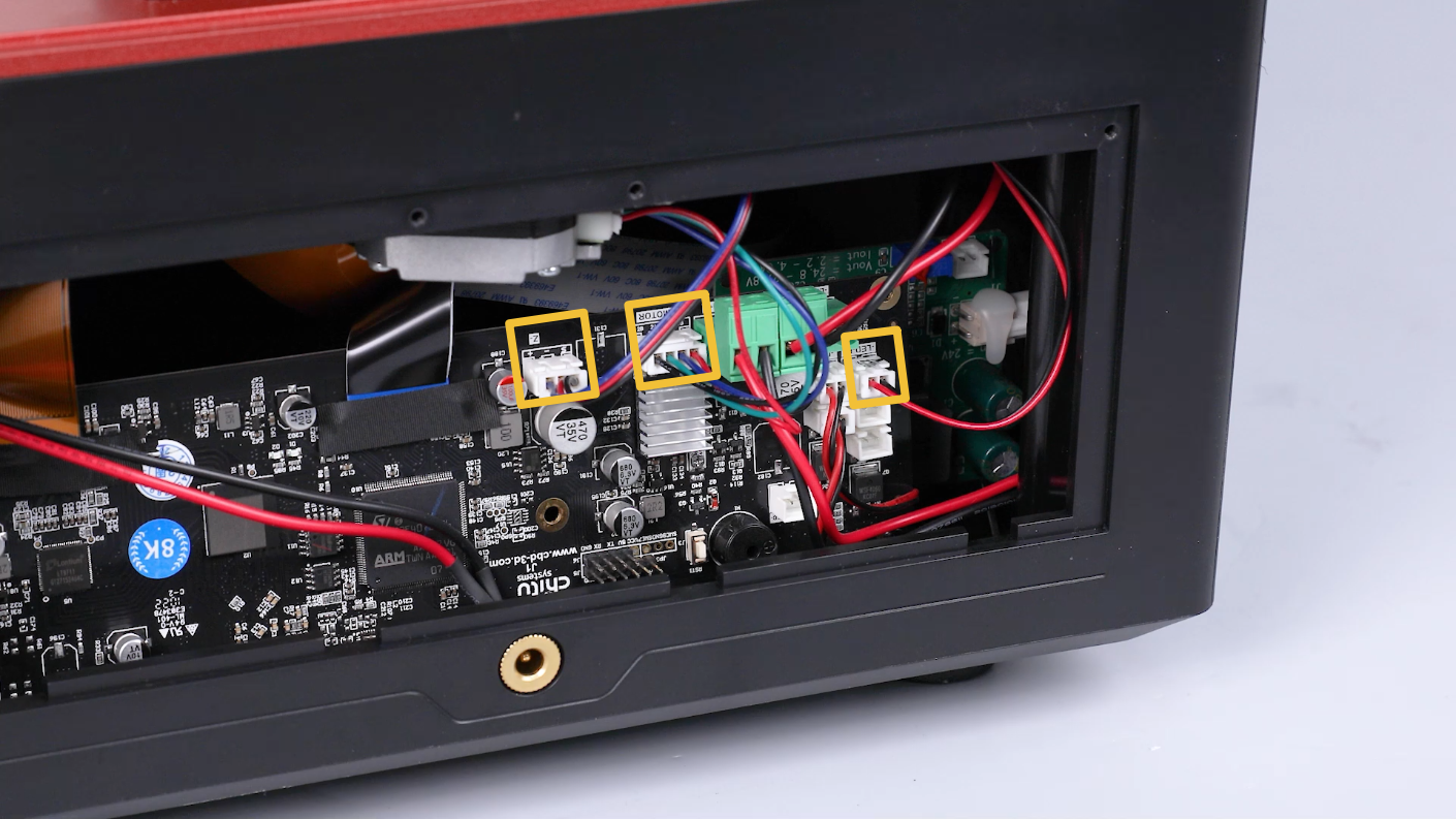
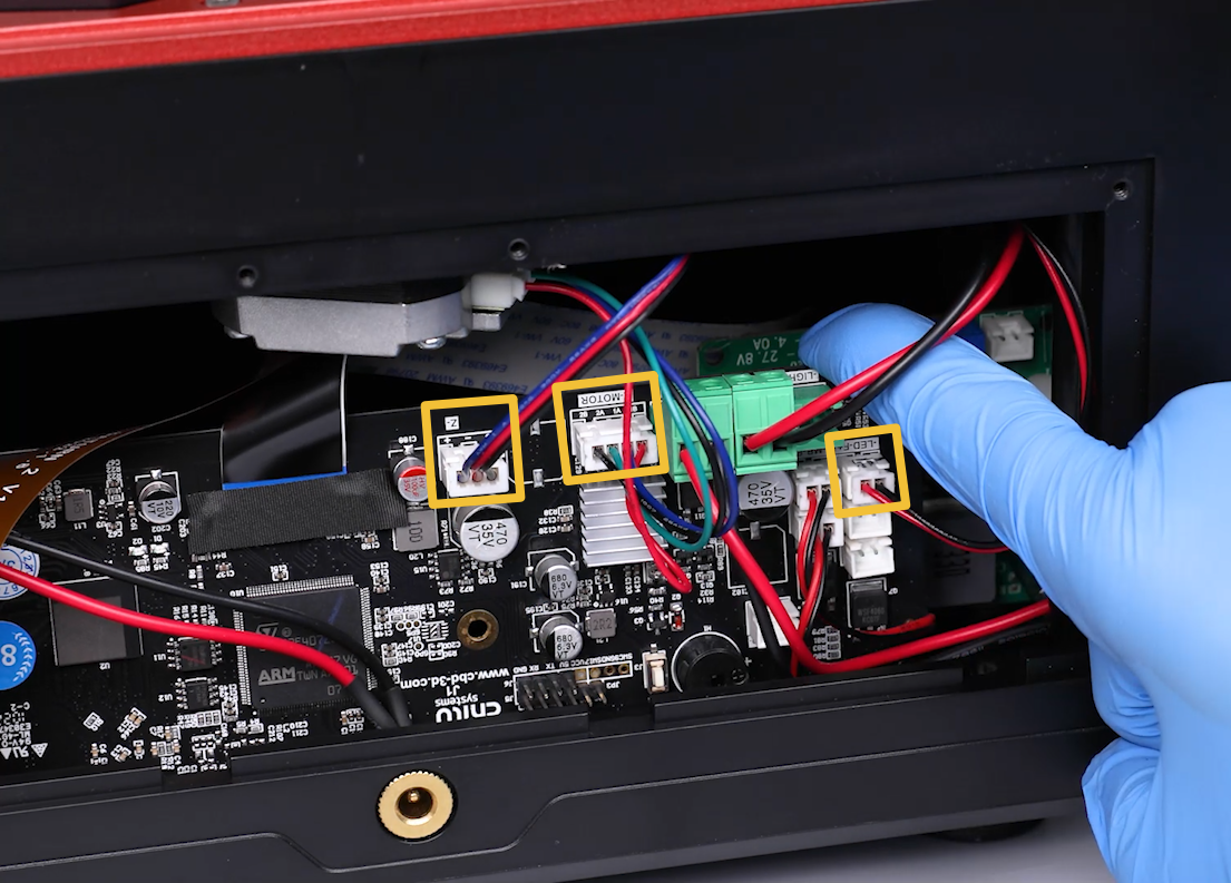
Unplug the cables of the air purifier, motor and limit switch on the motherboard.
-
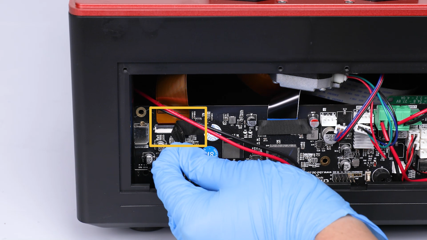
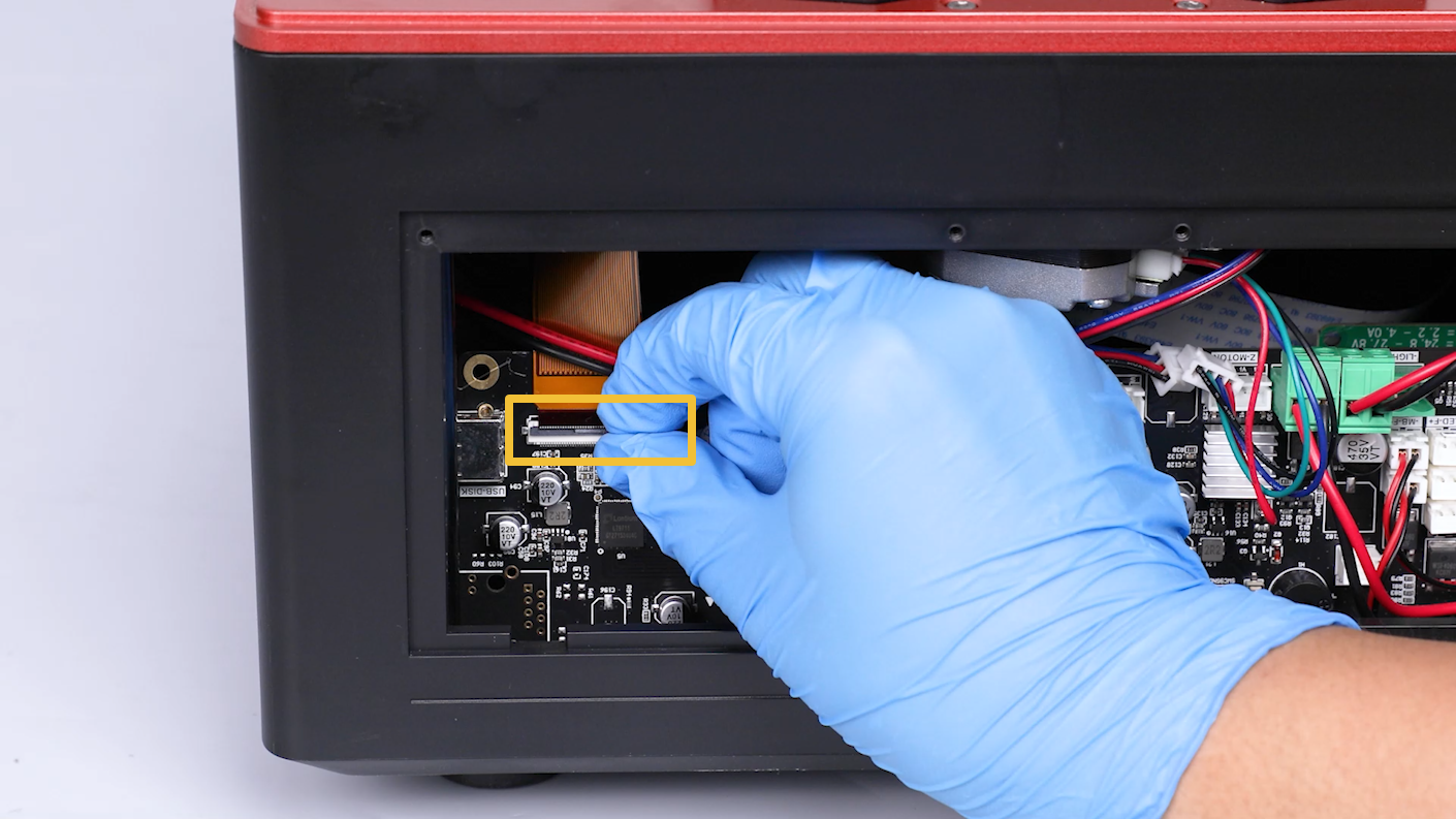
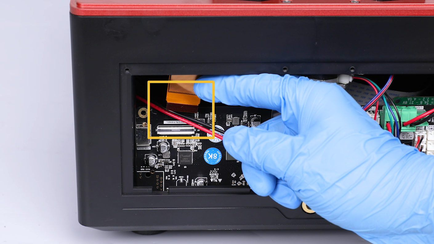
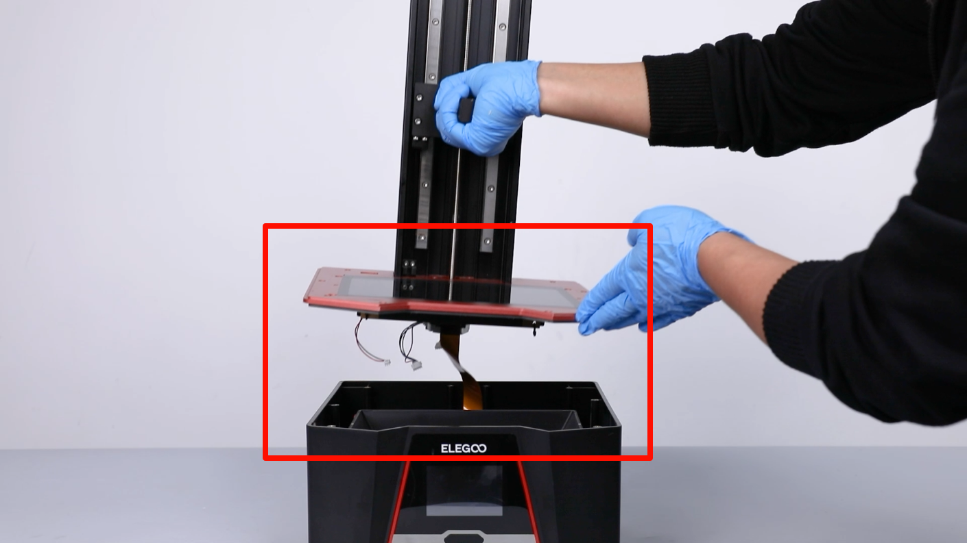
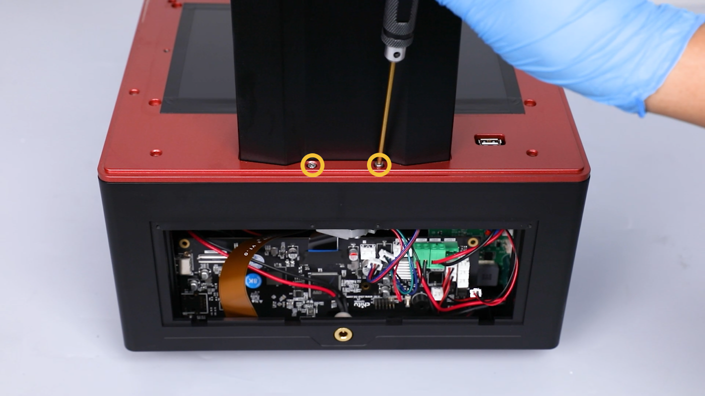
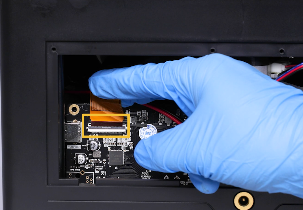
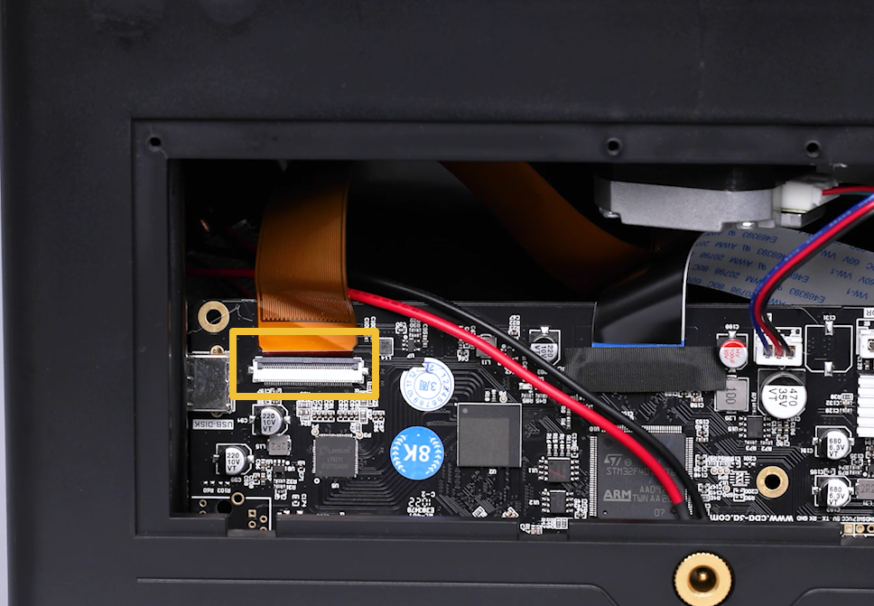
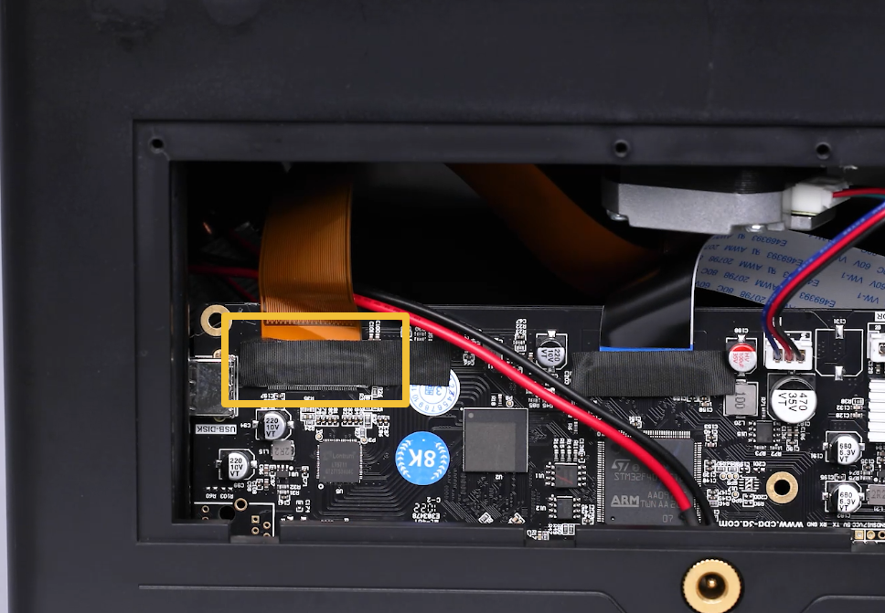
Tear off the black tape attached to the LCD screen port on the motherboard. Lift the clip of the port. Remove the cable of the LCD screen port.
Note: Reserve the tape for future use.
-
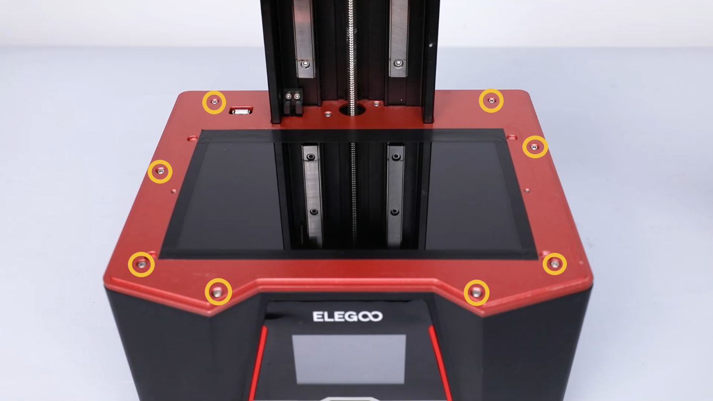
Loosen the ten screws securing the middle housing with a 2.5mm Allen key.

-
Lift to remove the middle housing.
Note: Organize the inner cables to avoid any damage.
-
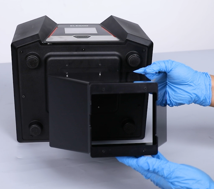
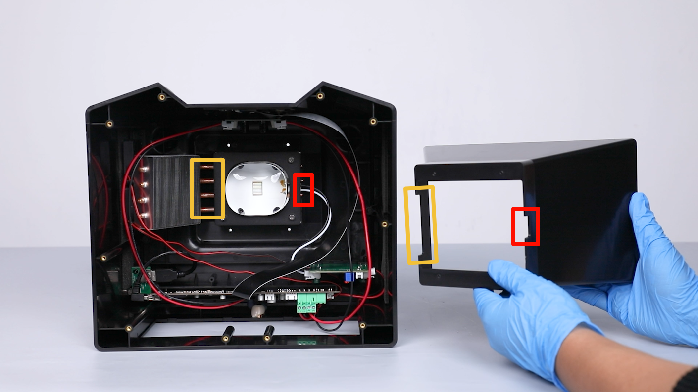
Loosen the 4 screws securing the lens shade at the bottom cover of the printer with a 2.0 mm Allen key. Remove the lens shade.
Note: Hold the lens shade to prevent it from falling while loosening the screws.
-
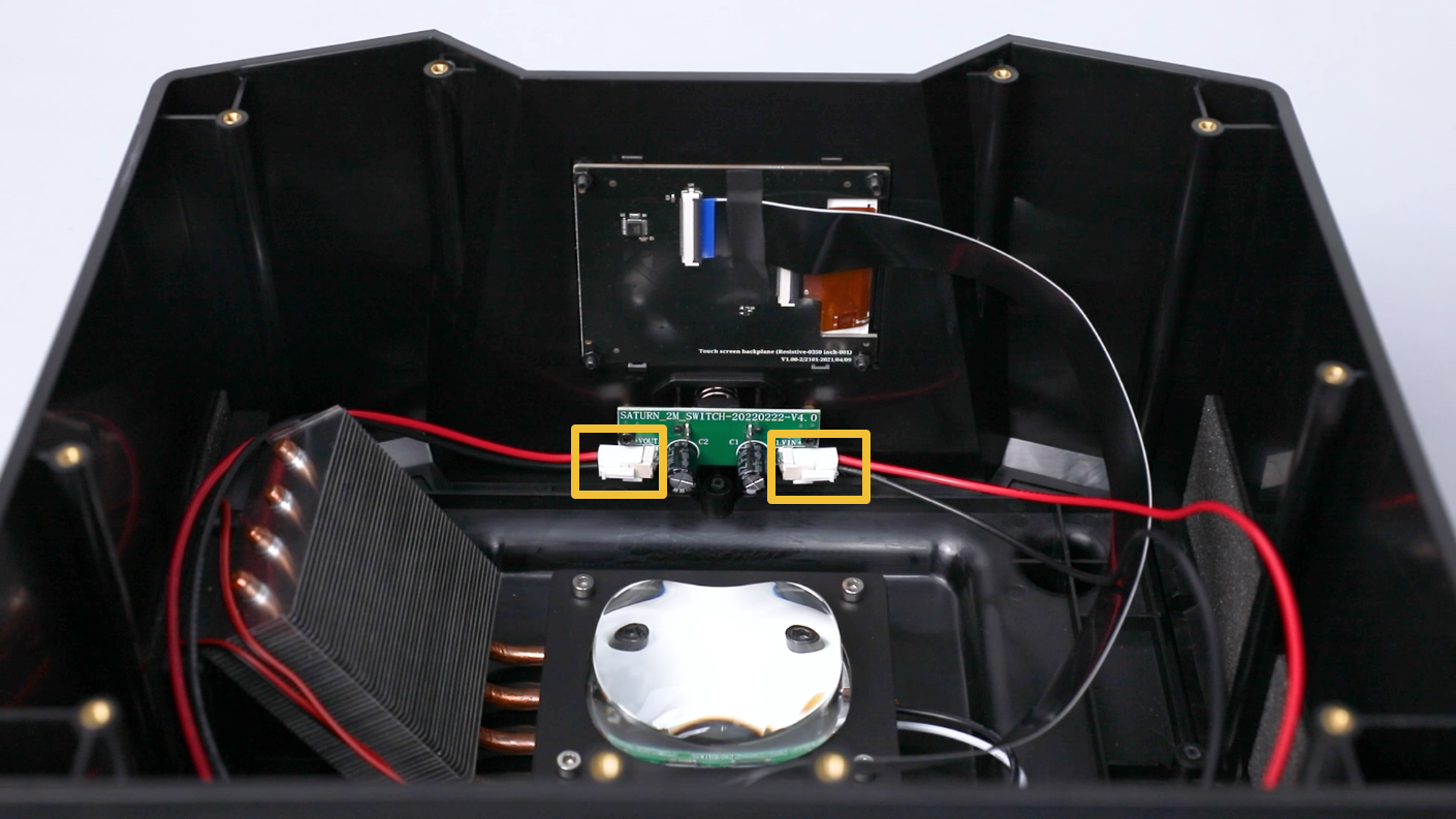
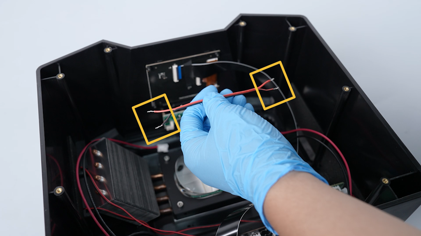
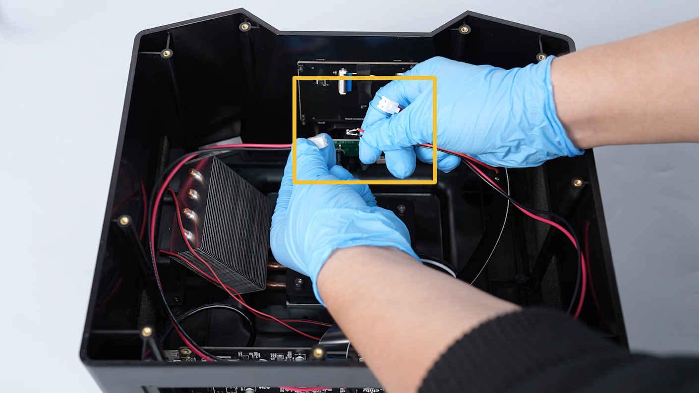
Disconnect the two connection cables on the PCB of power switch.
-
Prepare two connection cables and strip the insulation from both ends.
-
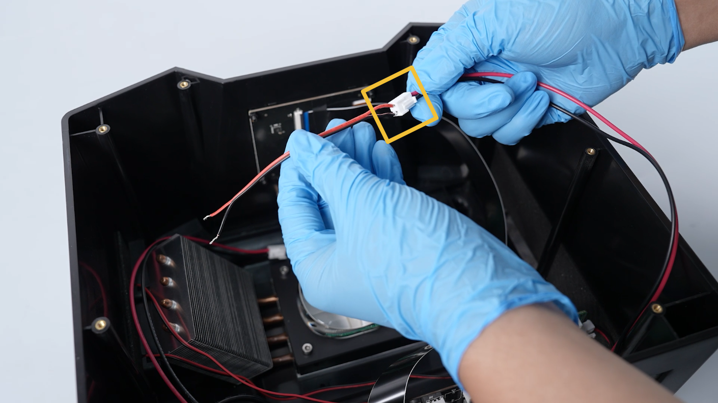
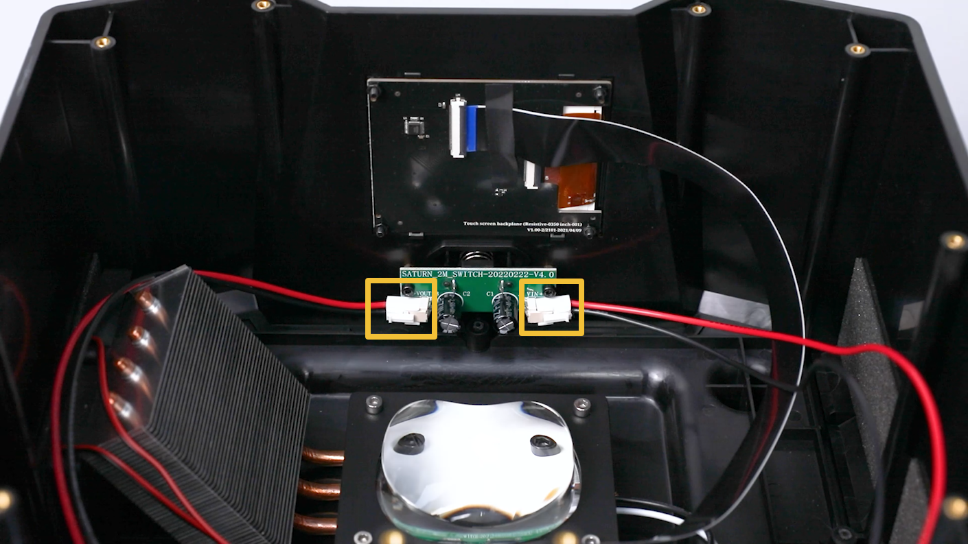
Insert the two pieces of connection cable into corresponding ports on the PCB.
Note: The red cable connects to the red cable core, and the black cable connects to the black cable core.
-
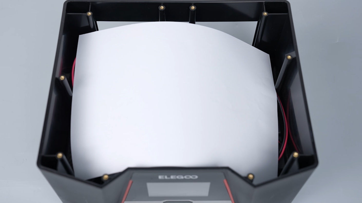
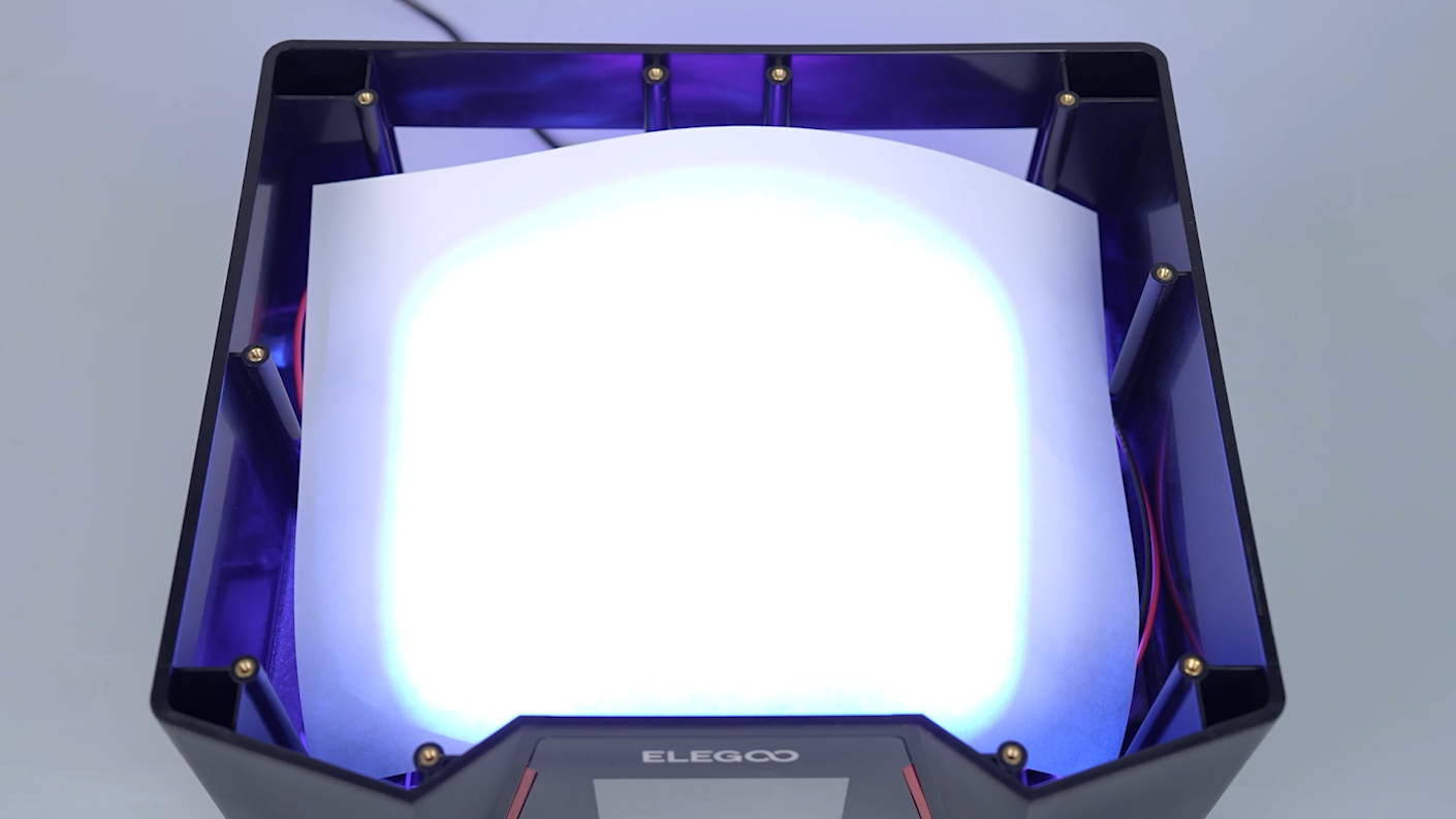
Prepare a piece of A4 paper and put it on the surface of the UV lamp to avoid blinding when the UV lamp is on.
-
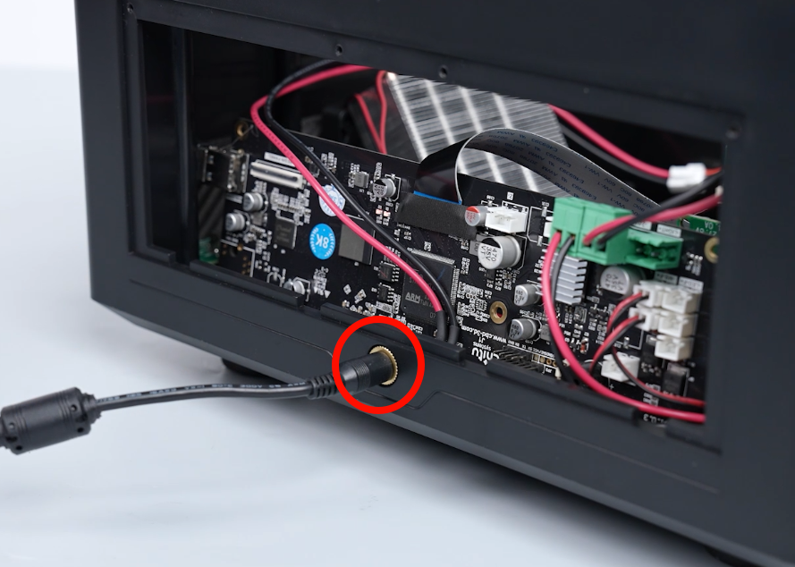
Plug in the printer's power cord and the touch screen turns on.
Note: If the touchscreen is unable to turn on, the connection cable might be loose. Unplug the power supply cable and reconnect the connection cable.

-
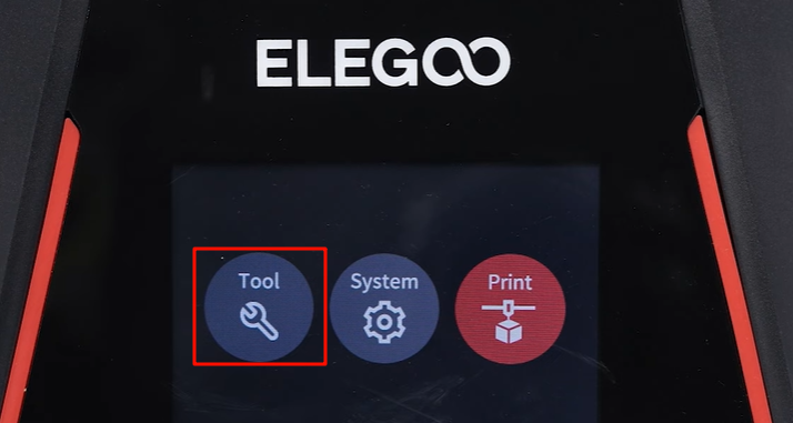
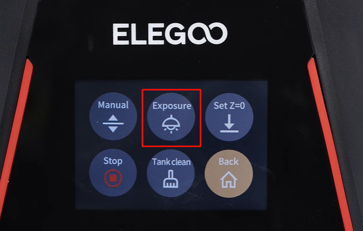
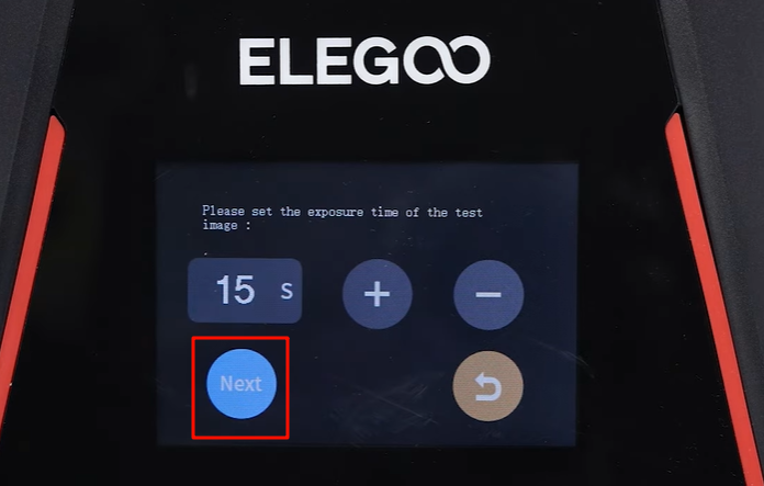
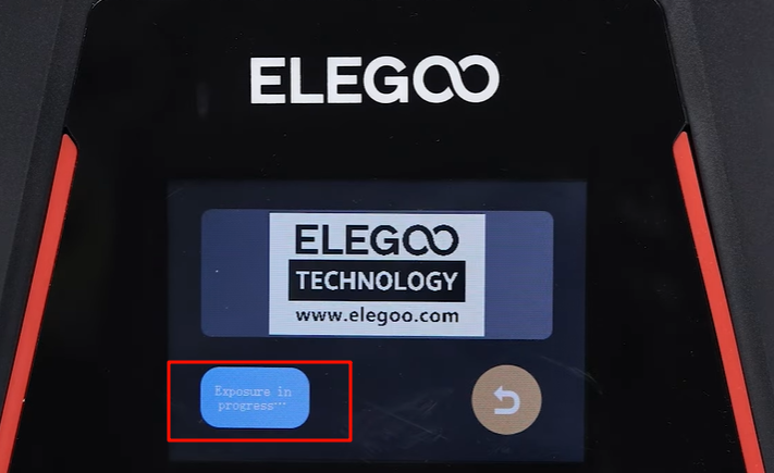
On the touch screen, click Tool - Exposure - Next.
-
Check if the UV light is on and if the printer restarts when the UV light is activated. If the UV light turns on normally.
Note: Reach out to official technical support for any follow-up feedback regarding the testing.
-
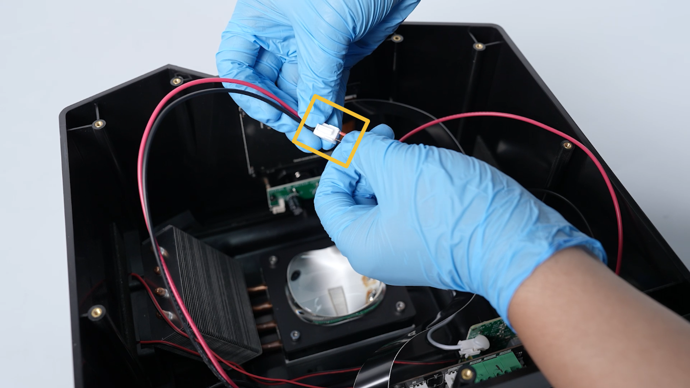
Unplug the power supply cable. Remove the connection cable between the two cables.
-
Insert the two cables into the PCB of the power switch.
-
Put the lens shade in the installation position by aligning it with the two slots. Tighten the 2 screws with a 2.0 mm Allen key.
-
Align the middle housing with the screw holes and put it in the installation position. Tighten ten screws with a 2.5mm Allen key.
Note: Organize the inner cables to avoid any damage.

-
Reconnect the cable of the air purifier to the LED-F port on the motherboard. Reconnect the motor cable to the Z-MOTOR port on the motherboard. Reconnect the limit switch cable to the Z- port on the motherboard.
-
Insert the LCD screen cable into the port on the motherboard. Adhere the black tape to the LCD cable port.
Note: The LCD screen cable has a fixed installation position.
-
Put the back cover in the installation position by aligning it with the screw holes. Tighten the 4 screws securing the back cover with a 2.0 mm Allen key.