¶ Get Battery Voltage
This sample program demonstrates how to use the ESP32's ADC (Analog-to-Digital Converter) to read battery voltage and display the real-time battery voltage value and charge percentage on a TFT LCD screen.
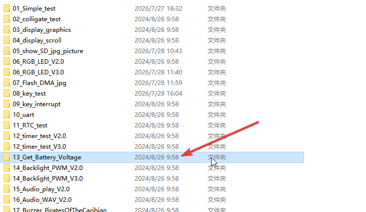
¶ Code Explanation
The sample code demonstrated here is based on the ESP32-WROOM-32E microcontroller. It utilizes the ESP32's internal ADC module to read analog voltage signals and displays the battery status on the LCD screen through the TFT_eSPI library.
¶ Hardware Connection
The pin connections between the ESP32-WROOM-32E, TFT LCD screen, and battery are as follows:
| Function | ESP32 Pin | Description |
|---|---|---|
| CS | 15 | Chip Select |
| DC/RS | 2 | Data/Command Selection |
| RESET | EN | Reset pin (shared with chip enable) |
| SDI/MOSI | 13 | Serial Data Input (Master Out Slave In) |
| SCK | 14 | Serial Clock |
| SDO/MISO | 12 | Serial Data Output (Master In Slave Out) |
| BL | 21 | Backlight Control |
| BAT_VOLT_ADC | 34 | Battery Voltage ADC Input |
| VCC | 5V | Power Supply |
| GND | GND | Ground |
¶ Basic Configuration
The following is the basic configuration part of the code:
- Library Introduction: Includes
Arduino.h(Arduino core library),TFT_eSPI.h(TFT display driver library), andesp_adc_cal.h(ESP32 ADC calibration library). - Pin Definition: Defines
PIN_BAT_VOLTas GPIO 34, used for reading the analog signal of battery voltage. - Object Instantiation: Creates
TFT_eSPI tftobject as the entry point for all subsequent screen operations. - Variable Definition:
targetTimeis used for periodic battery voltage updates, andbvstores the battery charge percentage.
¶ Detailed Explanation of setup() Function
The setup() function completes the initialization of the serial port and TFT screen, and draws the battery icon. It runs only once when the ESP32 is powered on or reset.
void setup()
{
    Serial.begin(115200);
    tft.begin();
    tft.setRotation(0);
    tft.setTextSize(3);
    tft.fillScreen(TFT_BLACK);
    tft.setTextColor(TFT_GREEN, TFT_BLACK);
    tft.drawRoundRect(tft.width()/2-51, tft.height()/2, 102, 22, 3, TFT_WHITE);
    tft.fillRect(tft.width()/2+51, tft.height()/2+6, 5, 10, TFT_WHITE);
}
¶ Serial Port Initialization
Serial.begin(115200);
- Sets the serial baud rate to 115200 for debugging information output. Compared to the default 9600 baud rate, 115200 enables faster data transmission.
¶ TFT Screen Initialization
tft.begin();
tft.setRotation(0);
tft.setTextSize(3);
tft.fillScreen(TFT_BLACK);
tft.setTextColor(TFT_GREEN, TFT_BLACK);
tft.begin(): Initializes the TFT screen, configuring SPI communication and display parameters.tft.setRotation(0): Sets the screen rotation direction to 0 degrees (default orientation).tft.setTextSize(3): Sets the text size to 3x.tft.fillScreen(TFT_BLACK): Fills the entire screen with black as the background.tft.setTextColor(TFT_GREEN, TFT_BLACK): Sets the text color to green with a black background.
¶ Drawing the Battery Icon
tft.drawRoundRect(tft.width()/2-51, tft.height()/2, 102, 22, 3, TFT_WHITE);
tft.fillRect(tft.width()/2+51, tft.height()/2+6, 5, 10, TFT_WHITE);
tft.drawRoundRect(): Draws the battery body outline (rounded rectangle) with a width of 102 pixels, height of 22 pixels, corner radius of 3 pixels, and white border.tft.fillRect(): Draws the battery positive terminal contact (small rectangle) with a width of 5 pixels, height of 10 pixels, and white fill. These two shapes together form the battery icon.
¶ Detailed Explanation of loop() Function
The loop() function is the main loop of the Arduino program, which runs repeatedly after the setup() function is executed. It periodically reads the battery voltage and updates the screen display.
void loop()
{
    if (millis() > targetTime)
    {
        esp_adc_cal_characteristics_t adc_chars;
        esp_adc_cal_value_t val_type = esp_adc_cal_characterize(ADC_UNIT_1, ADC_ATTEN_DB_11, ADC_WIDTH_BIT_12, 1100, &adc_chars);
        uint32_t raw = analogRead(PIN_BAT_VOLT);
        uint32_t v1 = esp_adc_cal_raw_to_voltage(raw, &adc_chars) * 2;

        tft.setCursor(tft.width()/2-50, tft.height()/4);
        tft.print(v1);
        tft.print("mV");

        if(v1<=2500)
        {
          bv = 0;
        }
        else if((v1>2500)&&(v1<=4200))
        {
          bv = (v1 - 2500)/17;
        }
        else
        {
          bv = 100;
        }
        tft.fillRoundRect(tft.width()/2-50, tft.height()/2+1,100, 20, 3, TFT_BLACK);
        tft.fillRoundRect(tft.width()/2-50, tft.height()/2+1, bv, 20, 3, TFT_GREEN);
        targetTime = millis() + 1000;
    }
    delay(20);
}
¶ Periodic Update Mechanism
if (millis() > targetTime)
Uses the millis() function to get the current runtime. When the time exceeds targetTime, voltage reading and display update are executed. targetTime is set to millis() + 1000 after each update, meaning updates occur every 1 second. The non-blocking timing approach is more flexible than delay().
¶ ADC Calibration
esp_adc_cal_characteristics_t adc_chars;
esp_adc_cal_value_t val_type = esp_adc_cal_characterize(ADC_UNIT_1, ADC_ATTEN_DB_11, ADC_WIDTH_BIT_12, 1100, &adc_chars);
esp_adc_cal_characteristics_t: Defines the ADC calibration characteristics structure for storing calibration parameters.esp_adc_cal_characterize(): Configures ADC calibration parameters, including:ADC_UNIT_1: Uses ADC1 channelADC_ATTEN_DB_11: Sets attenuation to 11dB, with a maximum measurable voltage of approximately 3.3VADC_WIDTH_BIT_12: ADC resolution of 12 bits (0-4095)1100: Reference voltage (mV)&adc_chars: Pointer to the structure storing calibration parameters
¶ Voltage Reading and Conversion
uint32_t raw = analogRead(PIN_BAT_VOLT);
uint32_t v1 = esp_adc_cal_raw_to_voltage(raw, &adc_chars) * 2;
analogRead(PIN_BAT_VOLT): Reads the raw ADC value (0-4095) from GPIO 34.esp_adc_cal_raw_to_voltage(): Converts the raw ADC value to an actual voltage value (mV).* 2: Since battery voltage typically passes through a voltage divider circuit (e.g., 10kΩ/10kΩ resistor divider), the ADC reads half of the actual voltage, so multiplying by 2 restores the real voltage.
¶ Voltage Display
tft.setCursor(tft.width()/2-50, tft.height()/4);
tft.print(v1);
tft.print("mV");
tft.setCursor(): Positions the cursor at the upper center of the screen.tft.print(v1): Prints the battery voltage value.tft.print("mV"): Prints the voltage unit.
¶ Battery Percentage Calculation
if(v1<=2500)
{
    bv = 0;
}
else if((v1>2500)&&(v1<=4200))
{
    bv = (v1 - 2500)/17;
}
else
{
    bv = 100;
}
Calculates battery percentage based on voltage using a linear piecewise approach:
- Voltage ≤ 2500mV: Battery level is 0% (battery depleted)
- Voltage 2500mV ~ 4200mV: Battery level varies linearly between 0% and 100%, calculated as
(voltage - 2500) / 17 - Voltage > 4200mV: Battery level is 100% (battery fully charged)
This formula is based on the discharge curve of a single-cell lithium-ion battery:
- Nominal voltage: 3.7V
- Full charge voltage: 4.2V
- Cutoff voltage: 2.5V
¶ Battery Icon Update
tft.fillRoundRect(tft.width()/2-50, tft.height()/2+1, 100, 20, 3, TFT_BLACK);
tft.fillRoundRect(tft.width()/2-50, tft.height()/2+1, bv, 20, 3, TFT_GREEN);
- First line: Fills the battery icon interior area with black (clears the previous charge display).
- Second line: Fills the new charge portion with green. The
bvvalue (0-100) is used directly as the fill width, enabling dynamic updating of the charge bar.
¶ Main Loop Delay
delay(20);
Adds a 20ms delay in the main loop to avoid CPU overload while maintaining responsiveness.
¶ Summary
This sample program implements battery voltage detection and display through the following steps:
- Initialization: Configures the serial port, initializes the TFT screen, and draws the battery icon outline.
- ADC Calibration: Configures the ESP32's ADC parameters to ensure voltage measurement accuracy.
- Voltage Acquisition: Reads the analog voltage value through the ADC and converts it to actual voltage.
- Charge Calculation: Calculates the battery charge percentage based on the voltage value.
- Real-time Display: Displays the current voltage value and charge icon on the TFT screen.
- Periodic Update: Repeats the above process every 1 second to achieve real-time monitoring.
The key functions used in the program include:
Serial.begin(): Initializes serial communicationtft.begin(): Initializes the TFT screentft.setRotation(): Sets screen rotation angletft.fillScreen(): Fills the entire screen with a specified colortft.setTextColor(): Sets text colortft.drawRoundRect(): Draws a rounded rectangle (battery frame)tft.fillRect(): Draws a filled rectangle (battery contact)tft.setCursor(): Sets the text cursor positiontft.print(): Prints text/values on the screentft.fillRoundRect(): Draws a filled rounded rectangle (charge fill)esp_adc_cal_characterize(): Configures ADC calibration parametersanalogRead(): Reads the raw value from an analog pinesp_adc_cal_raw_to_voltage(): Converts raw ADC value to voltagemillis(): Gets system runtime in milliseconds
¶ Modification Instructions
If you need to modify the code to adapt to different hardware or display effects, you can refer to the following aspects for adjustment:
-
Modify ADC Input Pin:
- Change the pin number in
#define PIN_BAT_VOLT 34to use another ADC pin
- Change the pin number in
-
Modify Voltage Divider Ratio:
- Adjust the
* 2multiplier. If using different divider resistors (e.g., 1MΩ/200kΩ), the divider ratio needs to be modified - Example: For a 1:5 divider ratio, change to
* 5
- Adjust the
-
Modify Battery Calculation Formula:
- Adjust voltage ranges based on different battery types (e.g., 2-cell series batteries)
- Modify the voltage thresholds 2500mV and 4200mV, and the divisor 17
-
Modify Update Period:
- Change the 1000 value in
targetTime = millis() + 1000to adjust the voltage refresh frequency (in milliseconds)
- Change the 1000 value in
-
Modify Display Color:
- Change
TFT_GREENto another color (e.g.,TFT_YELLOW,TFT_RED) to change the charge fill color
- Change
-
Modify Battery Icon Size:
- Adjust the coordinate and size parameters in
drawRoundRect()andfillRect()
- Adjust the coordinate and size parameters in
-
Add Low Battery Warning:
- Add logic in
loop()to change color or add a warning message when the charge level falls below a certain threshold
- Add logic in
-
Modify ADC Attenuation:
- For measuring higher voltages, change
ADC_ATTEN_DB_11toADC_ATTEN_DB_12(supports up to 3.6V)
- For measuring higher voltages, change