¶ overview
This tutorial only covers basic operations of the device. The provided libraries are merely sufficient to run the sample programs. You need to explore on your own if you wish to achieve other visual effects and functions.
¶ Arduino Download
Please refer to the link below for software download and installation guidance:
https://wiki.elegoo.com/oshw-getting-started-&-kits/ide-download
If the serial port cannot be detected normally, troubleshoot according to the link below:
https://wiki.elegoo.com/oshw-getting-started-&-kits/ch340
All materials are available via the link below. Click the blue button to download them. Please check the documents for detailed operation steps. This tutorial series only covers essential environment installation and code explanation. If you need more comprehensive content, you may combine the provided materials for independent development and configuration.
If you find that the files in the package do not match the tutorial or some files are missing during later‑stage learning, click the download button inside the PDF tutorial to get the independent code package for this tutorial. You may also contact customer service to report the problem for an update.
Since some sample codes are highly similar, no‑further explanation will be provided. This is not missing‑content of the tutorial. You may test them on your own if needed.
¶ Library Installation
Please refer to the link below for detailed steps of library installation:
https://wiki.elegoo.com/oshw-getting-started-&-kits/library-Installation
After downloading and extracting the files, locate the provided library files following the path shown in the figure below.
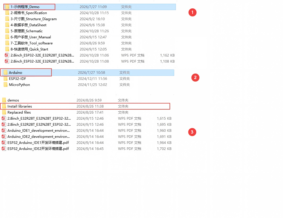
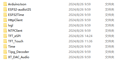
Open the install libraries folder to view all library files ready for installation. If you have installed similar libraries before, you can safely overwrite them. If you no longer need certain libraries later, or you want to use official versions instead, delete the existing files before downloading anew.
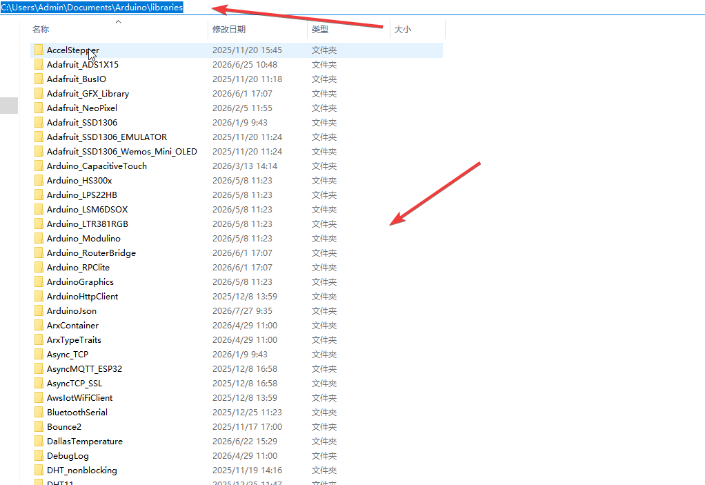
There are two methods to add library files. The first one is simple and efficient: copy all library files directly into the library folder of the Arduino IDE. The default path is shown below:
C:\Users\Admin\Documents\Arduino\libraries. Please refer to the figure below for details:
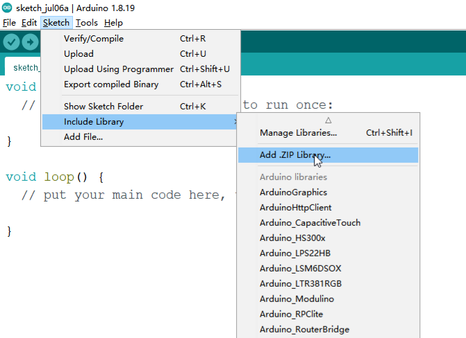
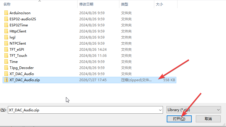
If you cannot locate the corresponding project file path, you may use the second method: compress the library files into a ZIP package and manually install the library via the IDE's file operation function. For specific operation steps, please refer to the link below:
https://wiki.elegoo.com/oshw-getting-started-&-kits/library-Installation
¶ Test
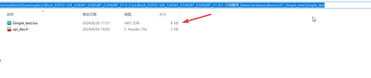
Go back to the upper directory and open the demo folder, where numerous sample programs are stored. Open the 01_Simple_test folder, then double-click the 01_Simple_test.ino file to launch it.
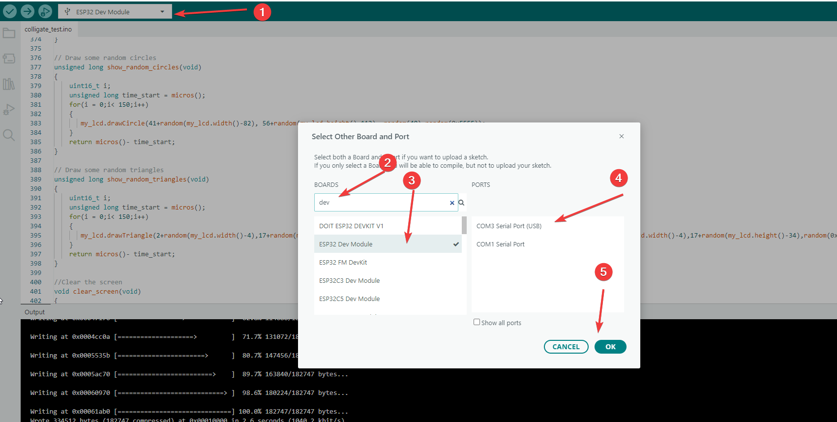
After opening the 01_Simple_test.ino file, connect the ESP32 main controller following the steps shown in the figure below.
¶ Code Explanation
This demo code is based on the ESP32-WROOM-32E development board.
¶ Dependent File Explanation
The code includes #include "spi_dev.h", which provides the following hardware-related macros and function declarations:
SPI_PORT: SPI port numberSPI_FREQUENCY: SPI communication frequencySPI_MODE: SPI mode configurationSPI_SCLK,SPI_MISO,SPI_MOSI: SPI pin definitionsLCD_CS,LCD_DC,LCD_RST,LCD_BL: LCD control pin definitionsLCD_CS_LOW,LCD_CS_HIGH: CS pin operation macrosLCD_DC_LOW,LCD_DC_HIGH: DC pin operation macrosSET_SPI_WRITE_MODE,SET_SPI_READ_MODE: SPI read/write mode switch macrosspi_write_8bit(),spi_write_16bit(): SPI data write functionsspi_write_buf,spi_write_len,spi_cmd,SPI_USR: DMA-related register pointers and flags
¶ Pin Definitions
| Pin Function | ESP32 Pin Number |
|---|---|
| CS | 15 |
| DC/RS | 2 |
| RESET | ESP32-EN |
| SDI/MOSI | 13 |
| SCK | 14 |
| SDO/MISO | 12 |
| BL | 21 |
| VCC | 5V |
| GND | GND |
¶ Color Definitions
#define RED 0xF800
#define GREEN 0x07E0
#define BLUE 0x001F
#define WHITE 0xFFFF
#define BLACK 0x0
#define GRAY  0X8430
The code defines six commonly used colors in RGB565 format:
- RED: Pure red (
0xF800) - GREEN: Pure green (
0x07E0) - BLUE: Pure blue (
0x001F) - WHITE: Pure white (
0xFFFF) - BLACK: Pure black (
0x0000) - GRAY: Gray (
0x8430)
¶ Screen Dimensions
#define LCD_WIDTH 240
#define LCD_HEIGHT 320
Defines the screen resolution as 240x320 pixels.
¶ SPI Command Definitions
#define WR_RAM_CMD 0x2C
#define RD_RAM_CMD 0x2E
#define SET_X_CMD  0x2A
#define SET_Y_CMD  0x2B
#define MADCTL_CMD 0x36
Defines basic SPI commands required for ST7796 communication:
WR_RAM_CMD: Write RAM commandRD_RAM_CMD: Read RAM commandSET_X_CMD: Set X coordinate commandSET_Y_CMD: Set Y coordinate commandMADCTL_CMD: Memory access control command
¶ SPI Communication Functions
¶ SPI_Start_Write() - Start SPI Write Operation
void SPI_Start_Write(void)
{
    if(lock_flag)
    {
       lock_flag = false;
       spi.beginTransaction(SPISettings(SPI_FREQUENCY, MSBFIRST, SPI_MODE));
       LCD_CS_LOW;
       SET_SPI_WRITE_MODE;
    }
}
This function initializes an SPI transaction, pulls the CS pin low to enable the LCD, and sets SPI to write mode. Uses lock_flag to prevent duplicate initialization.
¶ SPI_End_Write() - End SPI Write Operation
void SPI_End_Write(void)
{
    if(!lock_flag)
    {
      lock_flag = true;
      LCD_CS_HIGH;
      SET_SPI_READ_MODE;
      spi.endTransaction();
    }
}
This function pulls the CS pin high to disable the LCD, restores SPI to read mode, and ends the SPI transaction.
¶ LCD_Write_Reg() - Write Register Address
void LCD_Write_Reg(uint8_t val)
{
    SPI_Start_Write();
    LCD_DC_LOW;
    spi_write_8bit(val);
    SPI_End_Write();
}
Sets the DC pin low to indicate a register address write, then sends the 8-bit register address via SPI.
¶ LCD_Write_Data_8Bit() - Write 8-bit Data
void LCD_Write_Data_8Bit(uint8_t val)
{
    SPI_Start_Write();
    LCD_DC_HIGH;
    spi_write_8bit(val);
    SPI_End_Write();
}
Sets the DC pin high to indicate data write, then sends 8-bit data via SPI.
¶ LCD_Write_Data_16Bit() - Write 16-bit Data
void LCD_Write_Data_16Bit(uint16_t val)
{
    SPI_Start_Write();
    LCD_DC_HIGH;
    spi_write_16bit(val);
    SPI_End_Write();
}
Sets the DC pin high, sends 16-bit data via SPI (used for color value transmission).
¶ LCD_Set_Windows() - Set Display Window
void LCD_Set_Windows(uint16_t sx, uint16_t sy, uint16_t ex, uint16_t ey)
{
    LCD_Write_Reg(SET_X_CMD);
    LCD_Write_Data_16Bit(sx);
    LCD_Write_Data_16Bit(ex);
    LCD_Write_Reg(SET_Y_CMD);
    LCD_Write_Data_16Bit(sy);
    LCD_Write_Data_16Bit(ey);
    LCD_Write_Reg(WR_RAM_CMD);
}
This function sets the LCD display area:
- Send
SET_X_CMDto set X-axis start and end coordinates - Send
SET_Y_CMDto set Y-axis start and end coordinates - Send
WR_RAM_CMDto prepare for pixel data writing
¶ SPI_Init() - SPI Initialization
void SPI_Init(void)
{
    spi.begin(SPI_SCLK, SPI_MISO, SPI_MOSI, -1);
}
Initializes the SPI bus, specifying SCLK, MISO, and MOSI pins.
¶ Lcd_Init() - LCD Initialization
void Lcd_Init(void)
{
  LCD_Write_Reg(0xCF);
  LCD_Write_Data_8Bit(0x00);
  LCD_Write_Data_8Bit(0xC9);
  LCD_Write_Data_8Bit(0X30);
  // ... more register configurations

  LCD_Write_Reg(0x11); // Exit Sleep
  delay(120);
  LCD_Write_Reg(0x29); // Display on
}
The LCD initialization process follows the ST7796 datasheet, including:
- Power control configuration (
0xCF,0xED,0xE8,0xCB,0xF7,0xEA) - Voltage control configuration (
0xC0,0xC1,0xC5,0xC7) - Memory access control (
0x36) - Pixel format setting (
0x3A) - Set to RGB565 format - Frame rate control (
0xB1) - Display function control (
0xB6) - Gamma correction (
0xE0,0xE1) - Exit sleep mode (
0x11) - Turn on display (
0x29)
¶ Write_color_Block() - Batch Write Color Data
void Write_color_Block(uint16_t color, uint32_t len)
{
    volatile uint32_t* wr_buf = spi_write_buf;
    uint32_t color32 = ((color << 8 | color >> 8) << 16) | (color << 8 | color >> 8);
    // ... batch write logic
}
This function uses ESP32's DMA functionality to batch write color data, optimizing fill speed. It converts 16-bit color values to 32-bit format, writing 32 pixels per data block.
¶ LCD_Clear_Screen() - Screen Clear Function
void LCD_Clear_Screen(uint16_t sx, uint16_t sy, uint16_t w, uint16_t h, uint16_t color)
{
    if((sx >= LCD_WIDTH) || (sy >= LCD_HEIGHT))
        return;
    if(((sx + w) > LCD_WIDTH) || ((sy + h) > LCD_HEIGHT))
        return;
    if(((w < 1) || (w > LCD_WIDTH)) || ((h < 1) || (h > LCD_HEIGHT)))
        return;
    LCD_Set_Windows(sx, sy, sx + w - 1, sy + h -1);
    LCD_DC_HIGH;
    SPI_Start_Write();
    Write_color_Block(color, w*h);
    SPI_End_Write();
}
This function fills a specified area with a single color:
- Boundary check: Ensure coordinates and dimensions are within valid range
- Set window: Call
LCD_Set_Windows()to set the display area - Batch write: Call
Write_color_Block()to fill color data
¶ setup() Function
void setup()
{
  pinMode(LCD_CS, OUTPUT);
  digitalWrite(LCD_CS, HIGH);
  pinMode(LCD_DC, OUTPUT);
  digitalWrite(LCD_DC, HIGH);
  pinMode(LCD_BL, OUTPUT);
  digitalWrite(LCD_BL, HIGH);
  SPI_Init();
  Lcd_Init();
}
The setup() function runs only once when the ESP32 is powered on or reset:
- Configure CS pin: Set as output, initialized to HIGH (disabled)
- Configure DC pin: Set as output, initialized to HIGH
- Configure backlight pin: Set as output, initialized to HIGH (backlight on)
- Initialize SPI: Call
SPI_Init() - Initialize LCD: Call
Lcd_Init()
¶ loop() Function
void loop()
{
   LCD_Clear_Screen(0, 0, LCD_WIDTH, LCD_HEIGHT, RED);delay(500);
   LCD_Clear_Screen(0, 0, LCD_WIDTH, LCD_HEIGHT, GREEN);delay(500);
   LCD_Clear_Screen(0, 0, LCD_WIDTH, LCD_HEIGHT, BLUE);delay(500);
   LCD_Clear_Screen(0, 0, LCD_WIDTH, LCD_HEIGHT, GRAY);delay(500);
   LCD_Clear_Screen(0, 0, LCD_WIDTH, LCD_HEIGHT, WHITE);delay(500);
   LCD_Clear_Screen(0, 0, LCD_WIDTH, LCD_HEIGHT, BLACK);delay(500);
   for(uint16_t i=0; i< 5000;i++)
   {
      LCD_Clear_Screen(random(LCD_WIDTH-1), random(LCD_HEIGHT-1), random(LCD_WIDTH), random(LCD_HEIGHT), random(0xFFFF));
   }
}
The loop() function is the main loop of the Arduino program, running repeatedly after setup() completes:
¶ Color Cycle Demonstration
Fills the entire screen with six colors in sequence, each color displayed for 500 milliseconds:
- RED → wait 500ms
- GREEN → wait 500ms
- BLUE → wait 500ms
- GRAY → wait 500ms
- WHITE → wait 500ms
- BLACK → wait 500ms
¶ Random Color Block Drawing
for(uint16_t i=0; i< 5000;i++)
{
    LCD_Clear_Screen(random(LCD_WIDTH-1), random(LCD_HEIGHT-1), random(LCD_WIDTH), random(LCD_HEIGHT), random(0xFFFF));
}
Loops 5000 times, drawing rectangles with random positions, sizes, and colors each time:
random(LCD_WIDTH-1): Random X coordinaterandom(LCD_HEIGHT-1): Random Y coordinaterandom(LCD_WIDTH): Random widthrandom(LCD_HEIGHT): Random heightrandom(0xFFFF): Random color (0x0000-0xFFFF, covering all RGB565 colors)
¶ Summary
This demo program demonstrates the basic screen clearing functionality of the ST7796 LCD screen through the following steps:
- Color and dimension definitions: Define common color values and screen resolution
- SPI communication implementation: Implement SPI read/write, register configuration, and window setting
- LCD initialization: Configure parameters according to the ST7796 datasheet
- Screen clearing function: Implement efficient screen area filling
- Demonstration loop: Display six solid colors sequentially, then draw random color blocks
Key functions used in the program:
SPI_Start_Write()/SPI_End_Write(): SPI transaction managementLCD_Write_Reg(): Write register addressLCD_Write_Data_8Bit()/LCD_Write_Data_16Bit(): Write dataLCD_Set_Windows(): Set display windowLcd_Init(): LCD initializationWrite_color_Block(): Batch write color data (DMA optimized)LCD_Clear_Screen(): Fill specified area
¶ Modification Notes
If you need to modify the display effect, you can adjust the following aspects:
-
Modify color cycle order:
- Adjust the order of color filling in the
loop()function
- Adjust the order of color filling in the
-
Modify color display duration:
- Change the delay value in
delay(500)(unit: milliseconds)
- Change the delay value in
-
Modify random block count:
- Change the loop count in
for(uint16_t i=0; i< 5000;i++)
- Change the loop count in
-
Add new colors:
- Add new RGB565 color macros in the color definition section
-
Modify screen resolution:
- Change the values of
LCD_WIDTHandLCD_HEIGHT(must match hardware screen)
- Change the values of
-
Modify SPI speed:
- Adjust the frequency parameter in
SPISettingswithinSPI_Start_Write()
- Adjust the frequency parameter in
-
Add custom patterns:
- Add new drawing logic in
loop()or create new functions
- Add new drawing logic in