¶ RGB LED Tri-Color Light Example
This sample program demonstrates how to control an RGB tri-color LED using the ESP32-WROOM-32E. It implements basic on/off control and blinking effects through digital I/O pins, and also demonstrates LED dimming functionality using the ESP32's LEDC (PWM) peripheral.
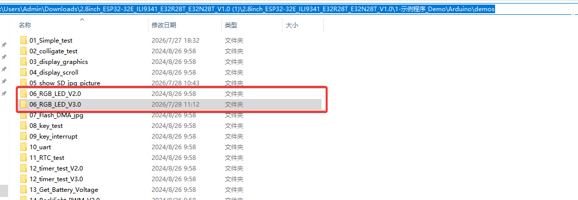
Note: Two versions (V2.0 and V3.0) are available, which correspond to different ESP32 Arduino core versions.
If your installed ESP32 Arduino core is V3.0, compiling and uploading code of V2.0 will trigger errors. Just switch to the V3.0 version code to solve this problem.
¶ Code Explanation
This sample code is based on the ESP32-WROOM-32E microcontroller. The program controls an RGB tri-color LED (common anode, lit at low level), sequentially displaying steady-on and blinking effects for red, green, and blue colors, and finally demonstrates gradual brightness dimming via PWM.
¶ Basic Configuration
The following is the basic configuration part of the code, including library inclusion, pin definitions, and global variable settings.
#include <Arduino.h>

#define RED_PIN 22
#define GREEN_PIN 16
#define BLUE_PIN 17

#define LED_ON  0
#define LED_OFF 1

int freq = 2000;
int channel = 0;
int resolution = 8;

const int led = RED_PIN;
- Library Inclusion: Includes the Arduino core library
Arduino.h, providing hardware abstraction for GPIO, PWM, and other functionalities. - Pin Definition: Defines three LED control pins corresponding to GPIO22 (red), GPIO16 (green), and GPIO17 (blue) of the ESP32-WROOM-32E.
- LED State Definition: Since the RGB LED uses common anode configuration (lit at low level),
LED_ON = 0(low level turns on) andLED_OFF = 1(high level turns off) are defined. - PWM Parameter Configuration:
freq = 2000: Sets PWM frequency to 2000Hzchannel = 0: Uses LEDC channel 0resolution = 8: Sets PWM resolution to 8 bits (0-255 brightness levels)
- PWM Pin Selection:
led = RED_PIN, selecting the red LED pin as the PWM demonstration object.
¶ Pin Wiring Description
| RGB LED Pin | ESP32-WROOM-32E Pin | Description |
|---|---|---|
| RED | GPIO22 | Red LED control |
| GREEN | GPIO16 | Green LED control |
| BLUE | GPIO17 | Blue LED control |
| VCC | 5V | Power supply positive |
| GND | GND | Power supply ground |
Note: The RGB LED in this example is a common anode type, lit at low level. If using a common cathode LED (lit at high level), swap the definitions of
LED_ONandLED_OFF.
¶ Detailed Explanation of setup() Function
The setup() function completes the initialization of GPIO pins and performs the initial LED state setting once after power-on.
void setup()
{
  pinMode(RED_PIN, OUTPUT);
  pinMode(GREEN_PIN, OUTPUT);
  pinMode(BLUE_PIN, OUTPUT);
  digitalWrite(RED_PIN, LED_OFF);
  digitalWrite(GREEN_PIN, LED_OFF);
  digitalWrite(BLUE_PIN, LED_OFF);
  delay(1000);
  digitalWrite(RED_PIN, LED_ON);
  digitalWrite(GREEN_PIN, LED_ON);
  digitalWrite(BLUE_PIN, LED_ON);
  delay(2000);
}
¶ GPIO Initialization
pinMode(RED_PIN, OUTPUT);
pinMode(GREEN_PIN, OUTPUT);
pinMode(BLUE_PIN, OUTPUT);
Configures the red, green, and blue pins as output mode to drive the LEDs.
¶ Initial LED State
digitalWrite(RED_PIN, LED_OFF);
digitalWrite(GREEN_PIN, LED_OFF);
digitalWrite(BLUE_PIN, LED_OFF);
Turns off all LEDs after power-on to ensure a safe initial state.
¶ All-On Test
delay(1000);
digitalWrite(RED_PIN, LED_ON);
digitalWrite(GREEN_PIN, LED_ON);
digitalWrite(BLUE_PIN, LED_ON);
delay(2000);
After waiting 1 second, simultaneously turns on the red, green, and blue LEDs for 2 seconds to verify hardware connections.
¶ Detailed Explanation of loop() Function
The loop() function is the main program loop, sequentially demonstrating steady-on and blinking effects for the RGB tri-color LEDs, and finally presenting gradual brightness dimming via PWM.
void loop()
{
  int i = 0;
  // Red phase
  digitalWrite(GREEN_PIN, LED_OFF);
  digitalWrite(BLUE_PIN, LED_OFF);
  digitalWrite(RED_PIN, LED_ON);
  delay(1500);
  for(i=0; i<6; i++)
  {
    digitalWrite(RED_PIN, LED_OFF);
    delay(500);
    digitalWrite(RED_PIN, LED_ON);
    delay(500);
  }
  // Green phase
  digitalWrite(RED_PIN, LED_OFF);
  digitalWrite(BLUE_PIN, LED_OFF);
  digitalWrite(GREEN_PIN, LED_ON);
  delay(1500);
  for(i=0; i<6; i++)
  {
    digitalWrite(GREEN_PIN, LED_OFF);
    delay(500);
    digitalWrite(GREEN_PIN, LED_ON);
    delay(500);
  }
  // Blue phase
  digitalWrite(RED_PIN, LED_OFF);
  digitalWrite(GREEN_PIN, LED_OFF);
  digitalWrite(BLUE_PIN, LED_ON);
  delay(1500);
  for(i=0; i<6; i++)
  {
    digitalWrite(BLUE_PIN, LED_OFF);
    delay(500);
    digitalWrite(BLUE_PIN, LED_ON);
    delay(500);
  }
  digitalWrite(RED_PIN, LED_OFF);
  digitalWrite(GREEN_PIN, LED_OFF);
  digitalWrite(BLUE_PIN, LED_OFF);
  // LEDC PWM dimming
  ledcAttachChannel(led, freq, resolution, channel);
  for (int dutyCycle = 255; dutyCycle >= 0; dutyCycle = dutyCycle - 5)
  {
    ledcWrite(led, dutyCycle);
    delay(100);
  }
  for (int dutyCycle = 0; dutyCycle <= 255; dutyCycle = dutyCycle + 5)
  {
    ledcWrite(led, dutyCycle);
    delay(100);
  }
  delay(1000);
  ledcDetach(led);
}
¶ Red LED Demonstration
digitalWrite(GREEN_PIN, LED_OFF);
digitalWrite(BLUE_PIN, LED_OFF);
digitalWrite(RED_PIN, LED_ON);
delay(1500);
for(i=0; i<6; i++)
{
  digitalWrite(RED_PIN, LED_OFF);
  delay(500);
  digitalWrite(RED_PIN, LED_ON);
  delay(500);
}
- Turns off green and blue LEDs, keeps only the red LED on for 1.5 seconds
- Red LED blinks 6 times: 500ms off and 500ms on each cycle, creating approximately 6 seconds of blinking effect
¶ Green LED Demonstration
digitalWrite(RED_PIN, LED_OFF);
digitalWrite(BLUE_PIN, LED_OFF);
digitalWrite(GREEN_PIN, LED_ON);
delay(1500);
for(i=0; i<6; i++)
{
  digitalWrite(GREEN_PIN, LED_OFF);
  delay(500);
  digitalWrite(GREEN_PIN, LED_ON);
  delay(500);
}
Same logic as the red LED demonstration, switching to green LED for steady-on and blinking effects.
¶ Blue LED Demonstration
digitalWrite(RED_PIN, LED_OFF);
digitalWrite(GREEN_PIN, LED_OFF);
digitalWrite(BLUE_PIN, LED_ON);
delay(1500);
for(i=0; i<6; i++)
{
  digitalWrite(BLUE_PIN, LED_OFF);
  delay(500);
  digitalWrite(BLUE_PIN, LED_ON);
  delay(500);
}
Same logic as the red LED demonstration, switching to blue LED for steady-on and blinking effects.
¶ PWM Gradient Dimming Demonstration
digitalWrite(RED_PIN, LED_OFF);
digitalWrite(GREEN_PIN, LED_OFF);
digitalWrite(BLUE_PIN, LED_OFF);
ledcAttachChannel(led, freq, resolution, channel);
for (int dutyCycle = 255; dutyCycle >= 0; dutyCycle = dutyCycle - 5)
{
  ledcWrite(led, dutyCycle);
  delay(100);
}
for (int dutyCycle = 0; dutyCycle <= 255; dutyCycle = dutyCycle + 5)
{
  ledcWrite(led, dutyCycle);
  delay(100);
}
delay(1000);
ledcDetach(led);
- Turn Off All LEDs: Before switching to PWM mode, first turn off all LEDs via
digitalWrite - Configure PWM Channel:
ledcAttachChannel(led, freq, resolution, channel)connects RED_PIN to LEDC channel 0, setting frequency to 2000Hz and resolution to 8 bits - Gradual Fade-Out (Bright to Dim): Gradually decreases the duty cycle from 255 (brightest) to 0 (dimmest), decrementing by 5 per step with 100ms interval, producing a fading-out effect
- Gradual Fade-In (Dim to Bright): Gradually increases the duty cycle from 0 (dimmest) to 255 (brightest), incrementing by 5 per step with 100ms interval, producing a fading-in effect
- Hold Delay: Maintains the brightest state for 1 second
- Detach PWM:
ledcDetach(led)disconnects the pin from the PWM channel, restoring it to regular GPIO control
Note: The ESP32's LEDC (LED Controller) is a dedicated peripheral designed for PWM output. Compared to the traditional
analogWrite(), it offers more powerful features including independent channel management and flexible frequency/resolution configuration.
¶ Summary
This sample program demonstrates the ESP32's control capabilities over an RGB tri-color LED through the following steps:
- Initialization: Configures GPIOs as output mode, initializes all LEDs in the off state, and performs a brief all-on test to verify hardware
- Sequential Steady-On and Blinking: Performs 1.5-second steady-on + 6-time blinking (approximately 6 seconds) demonstrations for red, green, and blue LEDs sequentially
- PWM Dimming: Uses the LEDC peripheral to implement fade-out and fade-in effects on the red LED, demonstrating 8-bit resolution PWM dimming capabilities
The key functions used in the program include:
pinMode(): Configures GPIO pin input/output modedigitalWrite(): Sets GPIO pin high/low levelledcAttachChannel(): Connects a pin to an LEDC PWM channelledcWrite(): Sets the PWM channel duty cycleledcDetach(): Disconnects a pin from the LEDC channeldelay(): Pauses execution for the specified number of milliseconds
¶ Modification Instructions
If you need to modify the code to change the display effects, you can refer to the following aspects for adjustments:
-
Modify Pin Definitions:
- Change the values of
RED_PIN,GREEN_PIN, andBLUE_PINto suit different hardware wiring
- Change the values of
-
Modify LED State Polarity:
- If using a common cathode LED, change
LED_ONto1andLED_OFFto0
- If using a common cathode LED, change
-
Modify Steady-On Duration:
- Adjust the
delay(1500)value to change the steady-on duration for each color
- Adjust the
-
Modify Blink Count and Speed:
- Change the loop count in
for(i=0; i<6; i++)to alter the number of blinks - Change the
delay(500)value inside the loop to alter the blink speed
- Change the loop count in
-
Modify PWM Parameters:
- Adjust
freq(frequency) andresolutionto change PWM output characteristics - Modify the step size (currently 5) and delay (currently 100ms) in the fade-in/fade-out loops to change gradient speed
- Adjust
-
Add Color Mixing Effects:
- Turn on multiple LED colors simultaneously at appropriate positions to create mixing effects (e.g., red + green = yellow)
-
Change LED Color for PWM Demonstration:
- Change the
ledvariable toGREEN_PINorBLUE_PINto demonstrate PWM dimming for other colors
- Change the