¶ Button-Controlled LED
This example program demonstrates how to use a button to control the switching of an RGB tri-color LED. Each time the button is pressed, the LED cycles through the sequence of Red → Green → Blue → All Off.
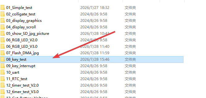
¶ Code Explanation
This example code is based on the ESP32-WROOM-32E development board. The core logic of the program is to control the display mode of the RGB LED by reading the button state.
¶ Hardware Connections
| Function | Pin Number | Description |
|---|---|---|
| RED | GPIO 22 | Red LED pin |
| GREEN | GPIO 16 | Green LED pin |
| BLUE | GPIO 17 | Blue LED pin |
| KEY | GPIO 0 | Button input pin (BOOT button) |
| VCC | 5V | Power supply positive |
| GND | GND | Ground |
¶ Basic Configuration
¶ Pin Definitions and Constants
#define RED_PIN 22
#define GREEN_PIN 16
#define BLUE_PIN 17

#define LED_ON  0
#define LED_OFF 1

#define KEY_PIN  0
- LED Pin Definitions: Define the GPIO pin numbers to which the red, green, and blue LEDs are connected, respectively.
- LED State Definitions: Since the ESP32's GPIO outputs low level to turn on the LED (common anode connection),
LED_ONis defined as 0 (low level turns on), andLED_OFFis defined as 1 (high level turns off). - Button Pin Definition: Define the GPIO 0 pin to which the button is connected. This pin is typically connected to the BOOT button on the development board.
¶ State Variable
int key_num = 0;
Defines an integer variable key_num to record the number of button presses, ranging from 0 to 4, corresponding to different LED states.
¶ setup() Function Explanation
The setup() function executes once at program startup and is mainly responsible for completing the initialization configuration of GPIO pins.
void setup()
{
  //Initialize LED GPIO, turn off tricolor light
  pinMode(RED_PIN, OUTPUT);
  pinMode(GREEN_PIN, OUTPUT);
  pinMode(BLUE_PIN, OUTPUT);
  digitalWrite(RED_PIN, LED_OFF);  //RED
  digitalWrite(GREEN_PIN, LED_OFF); //GREEN
  digitalWrite(BLUE_PIN, LED_OFF); //GREEN
  //Initialize KEY GPIO
  pinMode(KEY_PIN,INPUT_PULLUP);
}
¶ LED Pin Initialization
pinMode(RED_PIN, OUTPUT);
pinMode(GREEN_PIN, OUTPUT);
pinMode(BLUE_PIN, OUTPUT);
Configure the three LED pins to output mode to drive the turning on and off of the LEDs.
¶ LED Initial State Setting
digitalWrite(RED_PIN, LED_OFF);
digitalWrite(GREEN_PIN, LED_OFF);
digitalWrite(BLUE_PIN, LED_OFF);
Set the three LEDs to the off state to ensure no LED is lit after power-on.
¶ Button Pin Initialization
pinMode(KEY_PIN, INPUT_PULLUP);
Configure the button pin to input mode and enable the internal pull-up resistor.
About Pull-up Resistor: The
INPUT_PULLUPmode connects an internal pull-up resistor to the pin. When the button is not pressed, the pin is pulled high (1); when the button is pressed, the pin is pulled low (0). This configuration eliminates the need for an external pull-up resistor.
¶ loop() Function Explanation
The loop() function is the main loop of the program. It runs continuously after the setup() initialization is completed, and is responsible for detecting the button state and controlling the LED switching.
void loop()
{
  if(!digitalRead(KEY_PIN))
  {
    delay(10);
    if(!digitalRead(KEY_PIN))
   {
      while(!digitalRead(KEY_PIN));
      ++key_num;
      switch(key_num)
      {
        case 1:
          digitalWrite(RED_PIN, LED_ON);
          break;
        case 2:
          digitalWrite(GREEN_PIN, LED_ON);
          break;
        case 3:
          digitalWrite(BLUE_PIN, LED_ON);
          break;
        case 4:
          key_num = 0;
          digitalWrite(RED_PIN, LED_OFF);
          digitalWrite(GREEN_PIN, LED_OFF);
          digitalWrite(BLUE_PIN, LED_OFF);
          break;
        default:
          break;
      }
    }
  }
}
¶ Button Detection Logic
Button detection employs a software debouncing technique to ensure that each button press triggers only one operation:
¶ Step 1: Detect Button Press
if(!digitalRead(KEY_PIN))
Use digitalRead() to read the button pin state. Since the button uses pull-up input mode, the pin is high level (1) when not pressed and low level (0) when pressed. After negation with !, the condition being true indicates that the button is pressed.
¶ Step 2: Delay for Debouncing
delay(10);
if(!digitalRead(KEY_PIN))
Delay 10 milliseconds and then detect the button state again. This is because physical buttons produce mechanical bounce at the moment of pressing and releasing, causing rapid level signal changes. A 10ms delay is sufficient to filter out bounce interference and ensure that a genuine button action is detected.
¶ Step 3: Wait for Button Release
while(!digitalRead(KEY_PIN));
Use a while loop to wait for the button to be released. Only after the button is released will the program continue to execute subsequent logic, preventing repeated triggers when held down.
¶ Button Counting and LED State Switching
++key_num;
switch(key_num)
{
  case 1:
    digitalWrite(RED_PIN, LED_ON);
    break;
  case 2:
    digitalWrite(GREEN_PIN, LED_ON);
    break;
  case 3:
    digitalWrite(BLUE_PIN, LED_ON);
    break;
  case 4:
    key_num = 0;
    digitalWrite(RED_PIN, LED_OFF);
    digitalWrite(GREEN_PIN, LED_OFF);
    digitalWrite(BLUE_PIN, LED_OFF);
    break;
  default:
    break;
}
After each valid button press, key_num is incremented by 1, and different LED states are switched through the switch statement:
| Button Press Count | Action | Effect |
|---|---|---|
| 1st press | Turn on red LED | Only red LED is lit |
| 2nd press | Turn on green LED | Only green LED is lit |
| 3rd press | Turn on blue LED | Only blue LED is lit |
| 4th press | Reset counter, turn off all LEDs | All off state |
| 5th press | Return to case 1 | Cycle restarts |
¶ Summary
This example program implements the button-controlled LED function through the following steps:
- Initialization: Configure LED pins to output mode and set them to the off state, and configure the button pin to input mode with pull-up resistor.
- Button Detection: Use
digitalRead()to detect the button state, combined withdelay()to implement software debouncing. - State Waiting: Use a
whileloop to wait for the button to be fully released. - Loop Counting: After each button trigger, the counter
key_numis incremented. - LED Control: Based on the counter value, control different colored LEDs to turn on or off through the
switchstatement.
Key functions used in the program include:
pinMode(): Configure the input/output mode of GPIO pinsdigitalRead(): Read the level state of a GPIO pindigitalWrite(): Set the level state of a GPIO pindelay(): Delay for a specified number of milliseconds, used for debouncing
¶ Modification Notes
If you need to modify the code behavior, you can refer to the following aspects for adjustment:
-
Change Button Pin:
- Change
#define KEY_PIN 0to another available GPIO pin number
- Change
-
Change LED Pins:
- Change the defined values of
RED_PIN,GREEN_PIN, andBLUE_PIN
- Change the defined values of
-
Change LED Lighting Logic:
- If your LEDs use common cathode connection (high level turns on), change
LED_ONto 1 andLED_OFFto 0
- If your LEDs use common cathode connection (high level turns on), change
-
Change Debouncing Time:
- Adjust the millisecond value in
delay(10), which can be adjusted to 5-20ms according to the button feel
- Adjust the millisecond value in
-
Add More LED States:
- Add more
casebranches in theswitchstatement to implement more color combinations (such as turning on multiple LEDs simultaneously to produce mixed color effects)
- Add more
-
Change Loop Order:
- Adjust the order or content of
casebranches to change the LED switching sequence
- Adjust the order or content of
-
Implement Other Features:
- For example, add long-press detection, implement PWM dimming control, or control LEDs via serial port