¶ Stepper motor
¶ Overview
In this lesson, you will learn a fun and easy way to drive a stepper motor.
¶ Component Introduction
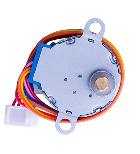
¶ Stepper Motor
A stepper motor is an electromechanical device which converts electrical pulses into discrete mechanical movements. The shaft or spindle of a stepper motor rotates in discrete step increments when electrical command pulses are applied to it in the proper sequence.
The motors rotation has several direct relationships to these applied input pulses. The sequence of the applied pulses is directly related to the direction of motor shafts rotation.
The speed of the motor shafts rotation is directly related to the frequency of the input pulses and the length of rotation is directly related to the number of input pulses applied.
One of the most significant advantages of a stepper motor is its ability to be accurately controlled in an open loop system. Open loop control means no feedback information about position is needed. This type of control eliminates the need for expensive sensing and feedback devices such as optical encoders.
Your position is known simply by keeping track of the input step pulses.
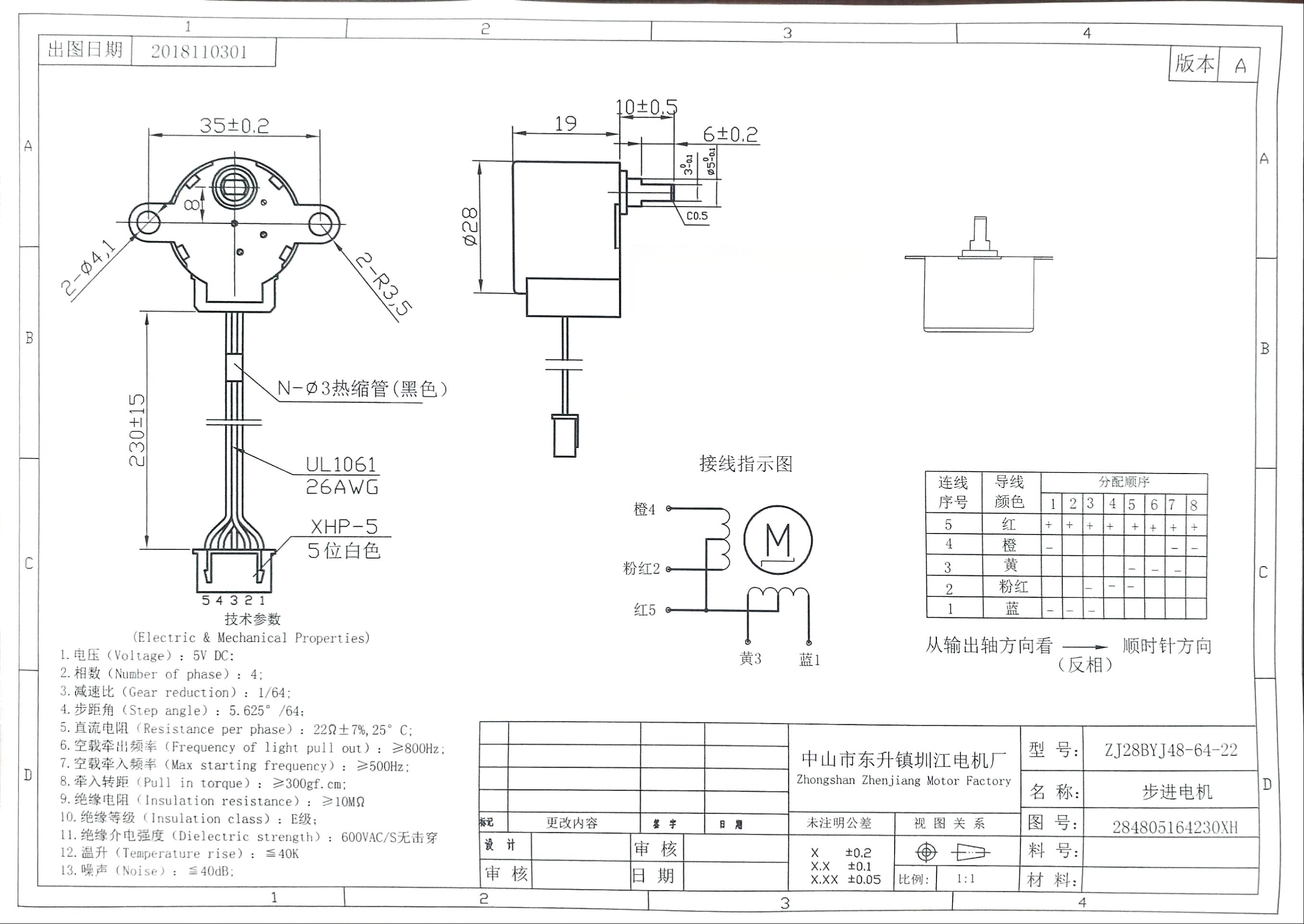
Stepper motor 28BYJ-48 Parameters
| Parameter | Value/Specification | Parameter | Value/Specification | |
|---|---|---|---|---|
| Model | 28BYJ-48 | In-traction Torque | >34.3mN.m(120Hz) | |
| Rated voltage | 5VDC | Self-positioning Torque | >34.3mN.m | |
| Number of Phase | 4 | Friction torque | 600-1200 gf.cm | |
| Speed Variation Ratio | 1/64 | Pull in torque | 300 gf.cm | |
| Stride Angle | 5.625°/64 | Insulated resistance | >10MΩ(500V) | |
| Frequency | 100Hz | Insulated electricity power | 600VAC/1mA/1s | |
| DC resistance | 50Ω±7%(25℃) | Insulation grade | A | |
| Idle In-traction Frequency | > 600Hz | Rise in Temperature | <40K(120Hz) | |
| Idle Out-traction Frequency | > 1000Hz | Noise | <35dB(120Hz,No load,10cm) |
Interfacing circuits
The bipolar stepper motor usually has four wires coming out of it. Unlike unipolar steppers, bipolar steppers have no common center connection. They have two independent sets of coils instead. You can distinguish them from unipolar steppers by measuring the resistance between the wires. You should find two pairs of wires with equal resistance. If you’ve got the leads of your meter connected to two wires that are not connected (i.e. not attached to the same coil), you should see infinite resistance (or no continuity).
Click the blue text to download the image locally and zoom in for a clearer view.
¶ ULN2003 Driver Board
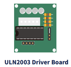
·Use ULN2003 driver chip, 500mA
·A. B. C. D LED indicating the four phase stepper motor working condition.
·White jack is the four phase stepper motor standard jack.
·Power pins are separated
·We kept the rest pins of the ULN2003 chip for your further prototyping.
The simplest way of interfacing a unipolar stepper to Arduino is to use a breakout for ULN2003A transistor array chip. The ULN2003A contains seven Darlington transistor drivers and is somewhat like having seven TIP120 transistors all in one package. The ULN2003A can pass up to 500 mA per channel and has an internal voltage drop of about 1V when on. It also contains internal clamp diodes to dissipate voltage spikes when driving inductive loads. To control the stepper, apply voltage to each of the coils in a specific sequence.
The sequence would go like this:
| LeadWire Color | --> CW Direction (1-2 Phase) | |||||||
|---|---|---|---|---|---|---|---|---|
| 1 | 2 | 3 | 4 | 5 | 6 | 7 | 8 | |
| 4 ORG | - | - | ||||||
| 3 YEL | ◇ | - | ||||||
| 2 PIK | - | - | ||||||
| 1 BLU | - | - | - | |||||
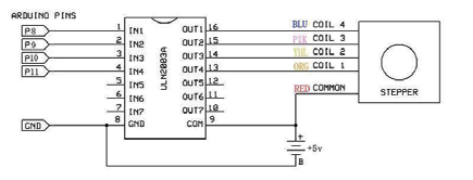
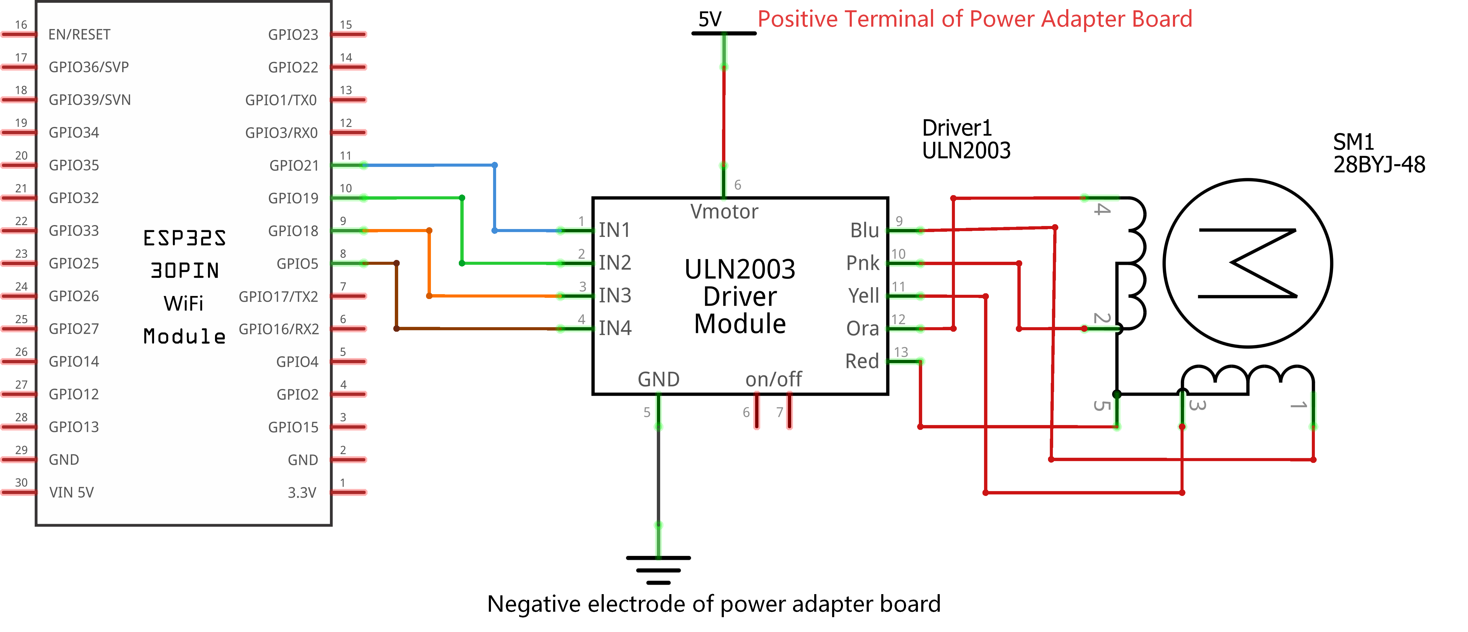
¶ Connection Schematic
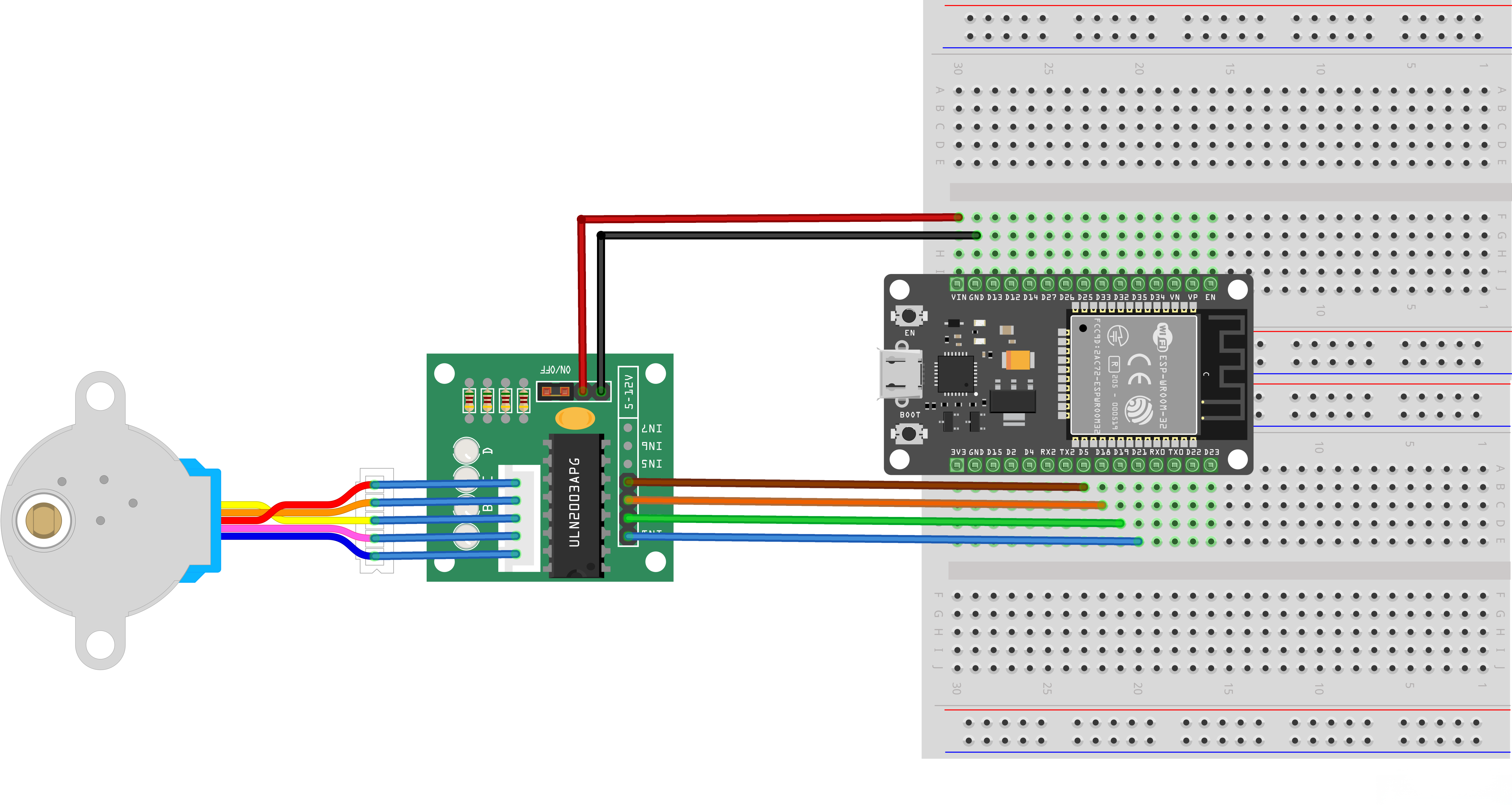
¶ Wiring diagram
¶ Practical Wiring Diagram
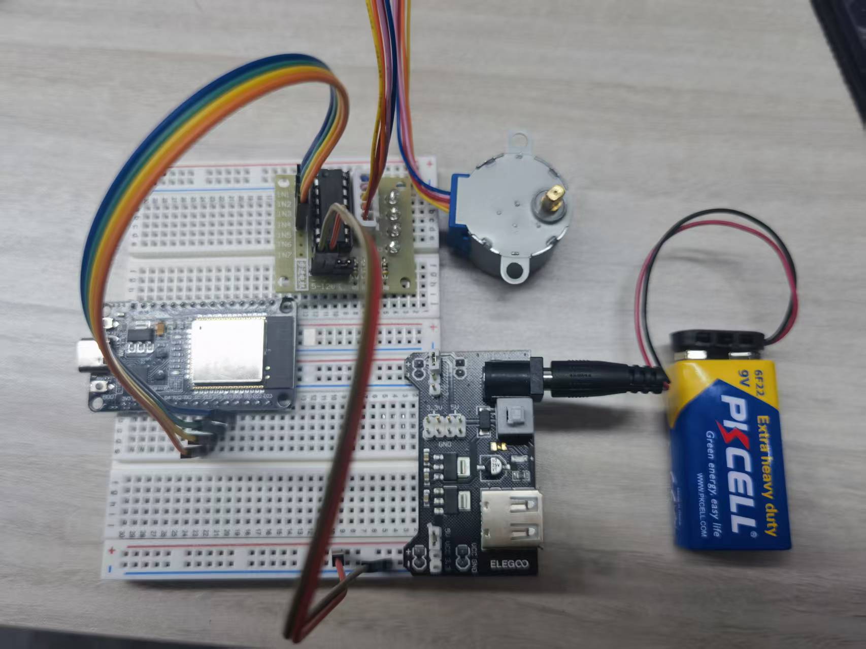
If you do not have a dedicated power supply, connect the positive terminal of the power source to the VIN pin of the ESP32 as shown in the figure below.
Note: If you encounter problems during use, please troubleshoot as follows:
1. First, check that the wiring is correct, especially the IN1~IN4 connections must match the wiring diagram provided with the code. If you want to change to other pins, ensure they correspond to the definitions in the code (the sequence in the code is: IN1 - IN3 - IN2 - IN4).
2. Next, check if the power supply voltage is stable. Low voltage may cause the stepper motor to stop running or have insufficient torque.
3. Finally, adjust the values in the code below to change the rotation speed.
const int rolePerMinute = 10; // Adjustable range of 28BYJ-48 stepper is 0~17 rpm
Crucial step: If you use a power adapter board, turn on the power switch. Power output is available only when the yellow indicator light on the module is on.
¶ Code
You can click the blue text link to download the program file to your local device, and double-click the file to open it after the download is complete. Please note: Before opening the file, ensure that you have installed the Arduino IDE development environment and completed the installation of relevant components such as the board support package and driver corresponding to the ESP32 development board. If you have any questions about this operation process, you can refer to the "part 1" chapter of the document for detailed guidance.
Click the Serial Monitor button to turn on the serial monitor. The basics about the serial monitor are introduced in details in tutorial 4 in part 2.
#include <Stepper.h>
const int stepsPerRevolution = 2048; // change this to fit the number of steps per revolution
const int rolePerMinute = 10; // Adjustable range of 28BYJ-48 stepper is 0~17 rpm// initialize the stepper library on pins :
Stepper myStepper(stepsPerRevolution, 21,18,19,5);//ln1-ln3-ln2-ln4
Library and Hardware Configuration:
#include <Stepper.h>: Includes the Arduino Stepper library for stepper motor controlconst int stepsPerRevolution = 2048: Defines the number of steps per full revolution for the 28BYJ-48 stepper motorconst int rolePerMinute = 10: Defines the motor speed in revolutions per minute (RPM)Stepper myStepper(stepsPerRevolution, 21,18,19,5): Creates a Stepper object with specified pins- Steps per revolution: 2048
- Pin connections: IN1=21, IN3=18, IN2=19, IN4=5 (ULN2003 driver board pin order)
void setup() {
myStepper.setSpeed(rolePerMinute);
// initialize the serial port:
Serial.begin(9600);
}
setup() Function:Initializes the system and configures the stepper motor.
myStepper.setSpeed(rolePerMinute): Sets the motor speed in revolutions per minute (10 RPM)Serial.begin(9600): Initializes serial communication at 9600 baud rate for operation feedback
Stepper Speed Setting:
- The setSpeed() function sets the approximate speed in RPM
- Actual speed may vary based on load and power supply
- 28BYJ-48 motors have a practical speed limit around 17 RPM
loop() Function Overview:The main loop that makes the stepper motor rotate alternately in clockwise and counterclockwise directions.
1. Clockwise Rotation Module:
// step one revolution in one direction:
Serial.println("clockwise");
myStepper.step(stepsPerRevolution);
delay(500);
- Operation Description: Makes the motor rotate one full revolution clockwise
- Direction Indication: Prints "clockwise" to the serial monitor
- Step Control:
myStepper.step(stepsPerRevolution)moves the motor 2048 steps (one full revolution) - Delay: 500ms pause after completion before next operation
2. Counterclockwise Rotation Module:
// step one revolution in the other direction:
Serial.println("counterclockwise");
myStepper.step(-stepsPerRevolution);
delay(500);
- Operation Description: Makes the motor rotate one full revolution counterclockwise
- Direction Indication: Prints "counterclockwise" to the serial monitor
- Step Control:
myStepper.step(-stepsPerRevolution)moves the motor -2048 steps (one full revolution in reverse) - Delay: 500ms pause after completion before next loop iteration
Stepper Motor Operation:
- Step Sequence: The Stepper library uses a four-phase sequence (IN1→IN3→IN2→IN4) for half-stepping mode
- Half-Stepping: Provides smoother operation and double the resolution compared to full-stepping
- Direction Control: Positive step values for clockwise, negative for counterclockwise
- Position Accuracy: Stepper motors maintain their position without a feedback mechanism
Pin Configuration (ESP32 to ULN2003 Driver):
| ESP32 Pin | ULN2003 Driver Pin | Motor Phase |
|---|---|---|
| GPIO 21 | IN1 | Phase 1 |
| GPIO 18 | IN3 | Phase 3 |
| GPIO 19 | IN2 | Phase 2 |
| GPIO 5 | IN4 | Phase 4 |
| 5V | VCC | Power supply |
| GND | GND | Ground |
Serial Monitor Output:
- "clockwise" - When the motor starts rotating clockwise
- "counterclockwise" - When the motor starts rotating counterclockwise
Troubleshooting:
- Motor not moving: Check power supply, connections, and pin configuration
- Incorrect direction: Swap any two adjacent phase wires
- Rough operation: Ensure proper step sequence and reduce speed
- Stalling: Reduce speed or check for excessive load
Stepper Library Functions:
Stepper(steps, pin1, pin2, pin3, pin4): Creates a 4-wire stepper motor objectsetSpeed(rpm): Sets the motor speed in revolutions per minutestep(steps): Moves the motor a specified number of steps
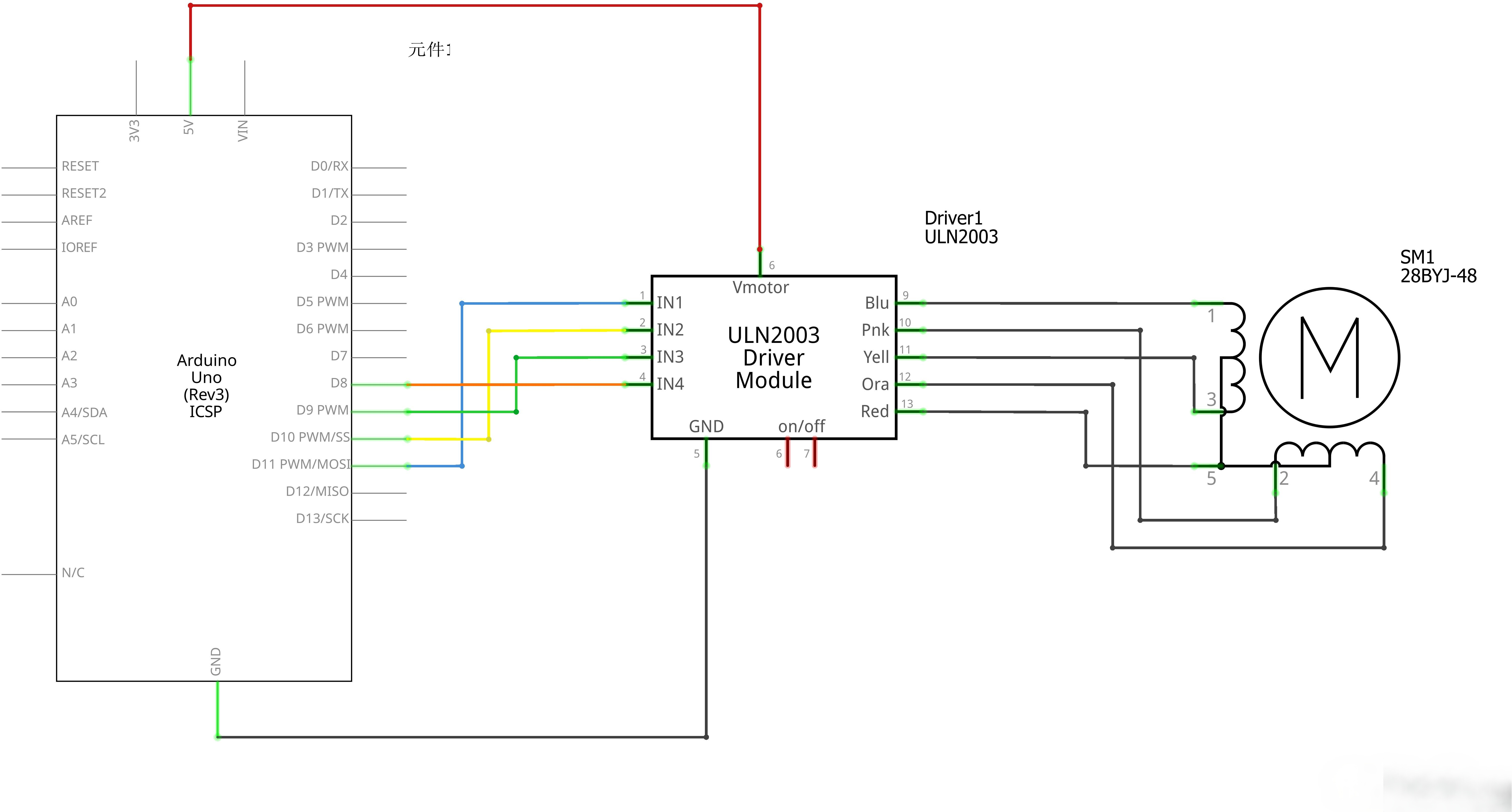
¶ Other ELEGOO boards
If you are using other motherboard models (such as UNO R3, MEGA 2560, NANO, UNO R4 series), please rest assured that the driving principle of the stepper motor is exactly the same.
For different motherboards, you only need to modify the pins to the corresponding available general-purpose pins.
For example: UNO R3 can change IN1~IN4 to D8~D11, and the operation is similar for other models.
Notes:
- Only general GPIO output pins can be used. Do NOT use dedicated power pins, analog input pins, or pins occupied for burning/booting.
- After modification, the hardware wiring of IN1~IN4 must be completely consistent with the pin sequence defined in the code.
For example:
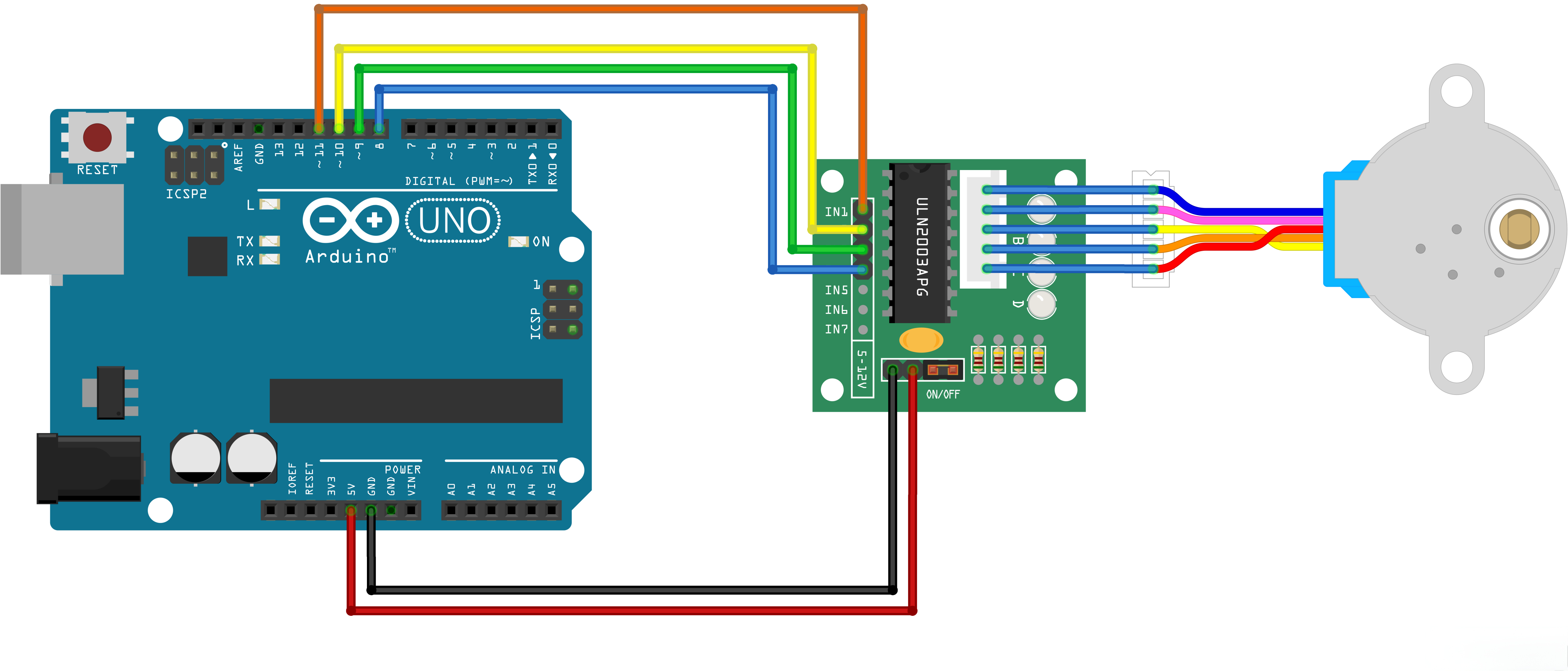
As shown in the figure below: When using the UNO R3 as the main control board, if IN1 to IN4 of the ULN2003 are connected to D11, D10, D9, D8 respectively, the pin definitions in the code must be updated accordingly.
If you connect them in reverse order to D8 to D11, you must also modify the code to match the wiring sequence.
#include <Stepper.h>
const int stepsPerRevolution = 2048; // change this to fit the number of steps per revolution
const int rolePerMinute = 10; // Adjustable range of 28BYJ-48 stepper is 0~17 rpm// initialize the stepper library on pins :
Stepper myStepper(stepsPerRevolution,11,9,10,8);//ln1-ln3-ln2-ln4