¶ Description
The relay module is an electrically operated switch that allows you to turn on or off a circuit using voltage and/or current much higher than a microcontroller could handle. There is no connection between the low voltage circuit operated by the microcontroller and the high power circuit. The relay protects each circuit from each other.
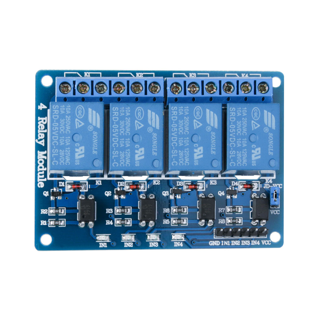
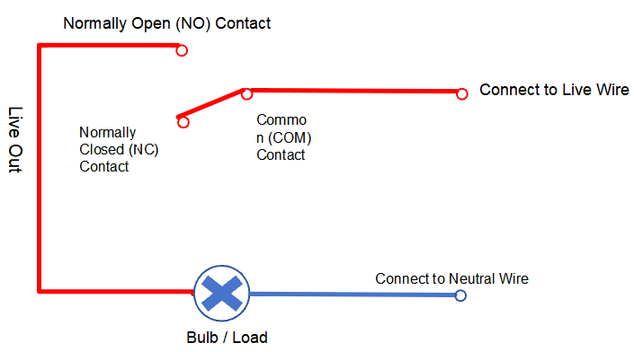
The each channel in the module has three connections named NC, COM, and NO. Depending on the input signal trigger mode, the jumper cap can be placed at high level effective mode which “closes” the normally open (NO) switch at high level input and at low level effective mode which operates the same but at low level input.
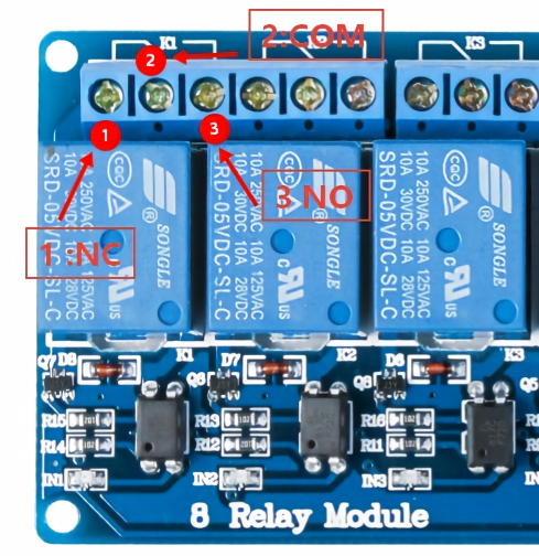
As shown in the figure below, if you have a multimeter, you can easily tell which terminal is Normally Open (NO) and which is Normally Closed (NC). For each individual relay channel on this module, counting from left to right: Pin 1 is NC (Normally Closed), Pin 2 is COM (Common), Pin 3 is NO (Normally Open).
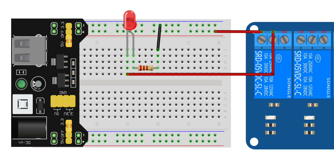
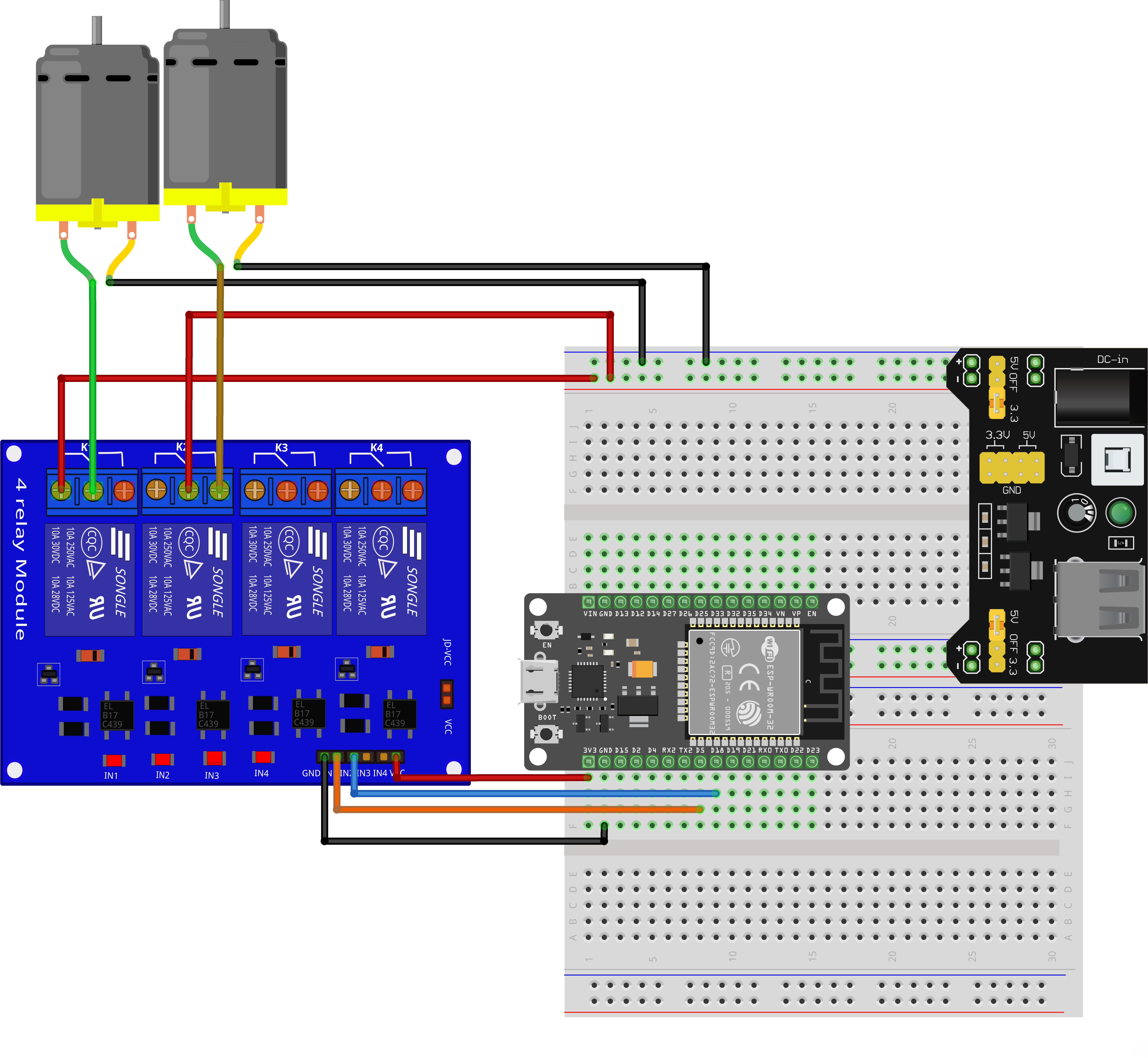
Unlike the wiring described above where the external power supply is connected to the normally‑open terminal, the power supply is connected to the common terminal in the figure below.
¶ Specifications
On-board EL817 photoelectric coupler with photoelectric isolating anti- interference ability strong
On-board 5V, 10A / 250VAC, 10A / 30VDC relays
Relay long life can absorb 100000 times in a row
Module can be directly and MCU I/O link, with the output signal indicator
Module with diode current protection, short response time
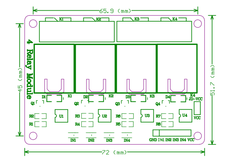
PCB Size: 72mm x 51.7mm
¶ Pin Configuration
¶ Module dimension drawing
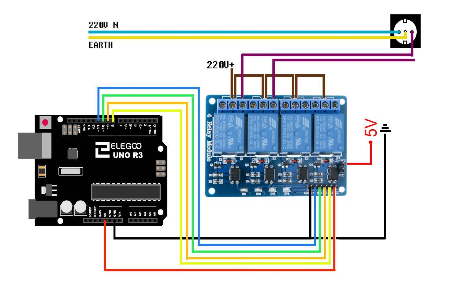
¶ Wiring Diagram
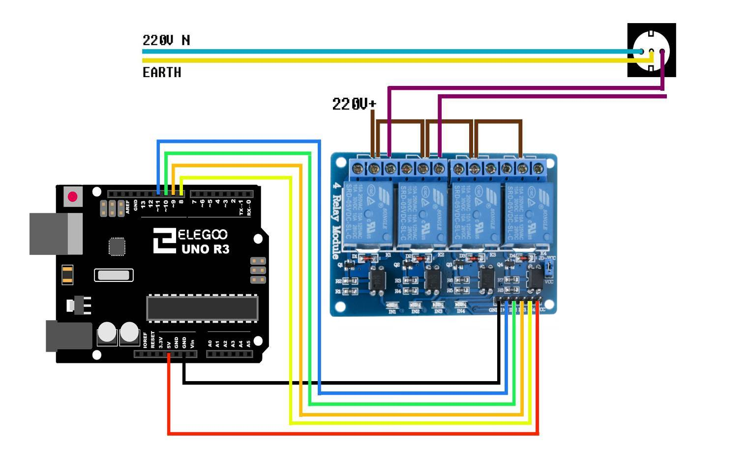
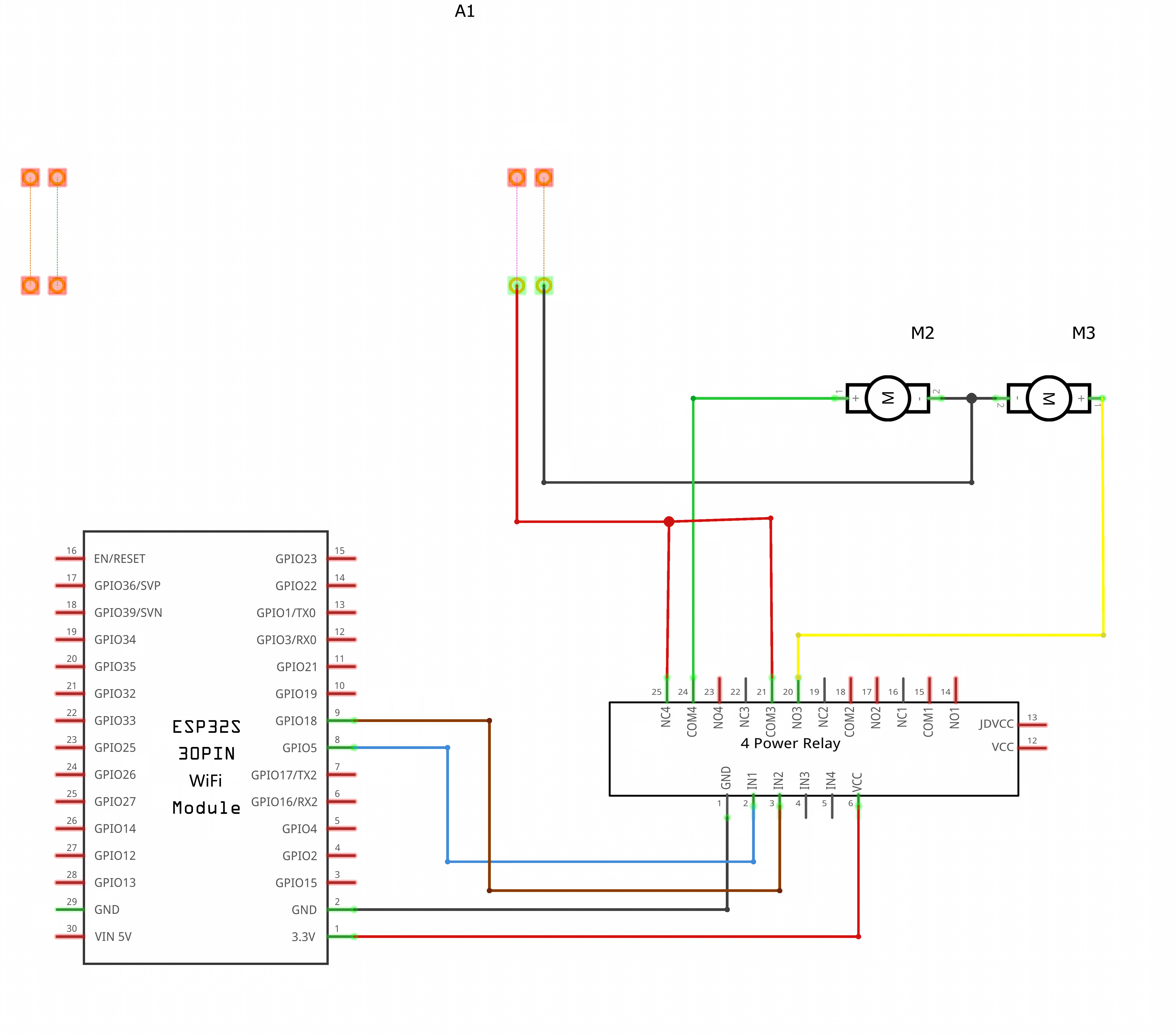
The upper wiring diagram shows high‑voltage connections for the UNO R3. The lower diagram is a low‑voltage demonstration wiring diagram for the ESP32. It includes two wiring methods: power supply connected to the normally‑closed terminal, and power supply connected to the common terminal.
¶ Schematic Diagram
This diagram corresponds to the ESP32 wiring diagram shown above.
¶ Sample Sketch
This piece of code is adapted for the UNO R3 board. To port it to other main‑controller boards, just modify the pin numbers in the code. For ESP32, you can use pins such as 5, 18, 19, 21. Modify as many pins as the number of relays you actually use.
void setup()

{   pinMode(11,OUTPUT);

    pinMode(10,OUTPUT);

    pinMode(9,OUTPUT);

    pinMode(8,OUTPUT);

}


void loop()

{    digitalWrite(11,LOW);

     delay(4000);

     digitalWrite(10, LOW);

     delay(4000);

    digitalWrite(9, LOW);

    delay(4000);

    digitalWrite(8, LOW);

    delay(4000);


    digitalWrite(11, HIGH);

    delay(4000);

    digitalWrite(10, HIGH);

    delay(4000);

    digitalWrite(9, HIGH);

    delay(4000);

    digitalWrite(8, HIGH);

    delay(4000);

}
¶ How to Test
The components to be used are:
- Microcontroller (any compatible arduino)
- 4 channel 5V 10A relay module
- Pin connectors
- USB cable
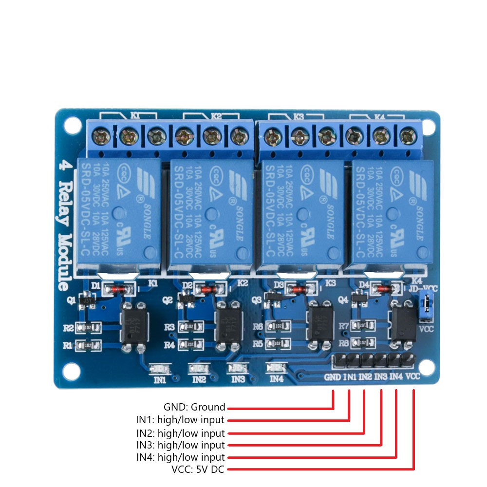
- Connect the components based on the figure shown in the wiring diagram using pin connectors. VCC and DJ-VCC pin is connected to the 5V power supply, GND pin is connected to the GND, IN1 and IN2 and IN3 and IN4 pins are connected to the digital I/O pin. Pin number will be based on the actual program code.
- After hardware connection, insert the sample sketch into the Arduino IDE.
- Using a USB cable, connect the ports from the microcontroller to the computer.
- Upload the program.
¶ Testing Results
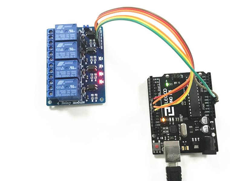
The figures below shows an alternate switching of the two relays every 4 seconds. A tick sound and a red LED would be observed.
¶ What does the jumper cap do when it connects to DJ-VCC?
Serves to power the part of the relays with the same Vcc of the opto-isolated part. If you want to separate the power supplies, remove the jumper and connect the external power supply between JD and GND without connecting the Arduino GND.
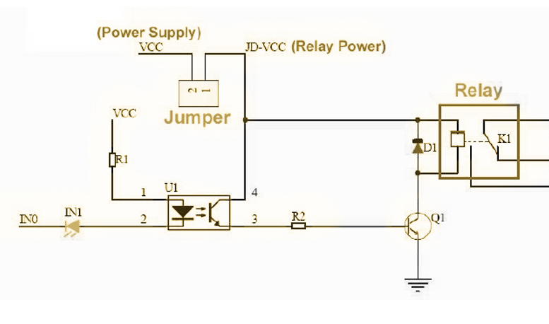
After removing the jumper cap, you need to power the jd-vcc separately as shown below: