¶ IR Receiver
¶ Overview
Using an IR Remote is a great way to have wireless control of your project.Infrared remotes are simple and easy to use. In this tutorial we will be connecting the IR receiver to the UNO,It is not necessary to use a specific library here; instead, write a program to parse which key of the infrared remote control is pressed when a signal is received.
In our sketch we will have all the IR Hexadecimal codes that are available on this remote, we will also detect if the code was recognized and also if we are holding down a key.
¶ Component Required:
(1) x Elegoo Uno R3
(1) x IR receiver module
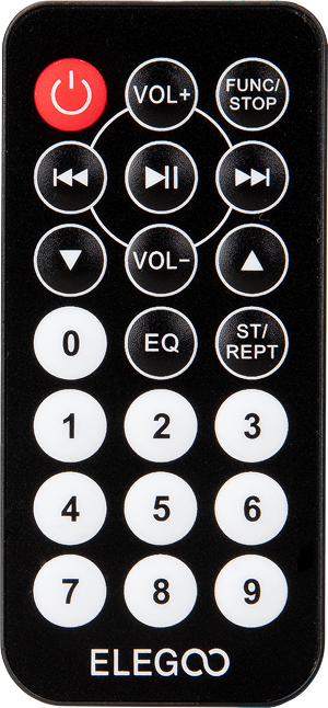
(1) x IR remote
(3) x F-M wires (Female to Male DuPont wires)
¶ Component Introduction
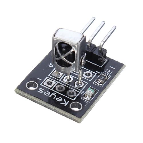
¶ IR RECEIVER SENSOR:
IR detectors are little microchips with a photocell that are tuned to listen to infrared light. They are almost always used for remote control detection - every TV and DVD player has one of these in the front to listen for the IR signal from the clicker. Inside the remote control is a matching IR LED, which emits IR pulses to tell the TV to turn on, off or change channels. IR light is not visible to the human eye, which means it takes a little more work to test a setup.
There are a few difference between these and say a CdS Photocells:
IR detectors are specially filtered for IR light, they are not good at detecting visible light. On the other hand, photocells are good at detecting yellow/green visible light, and are not good at IR light.
IR detectors have a demodulator inside that looks for modulated IR at 38 KHz. Just shining an IR LED won't be detected, it has to be PWM blinking at 38KHz. Photocells do not have any sort of demodulator and can detect any frequency (including DC) within the response speed of the photocell (which is about 1KHz)
IR detectors are digital out - either they detect 38KHz IR signal and output low (0V) or they do not detect any and output high (5V). Photocells act like resistors, the resistance changes depending on how much light they are exposed to.
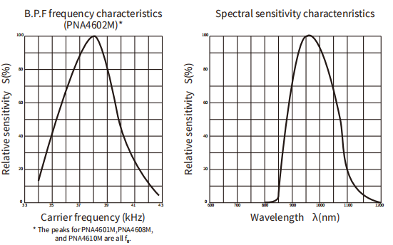
As you can see from these datasheet graphs, the peak frequency detection is at 38 KHz and the peak LED color is 940 nm. You can use from about 35 KHz to 41 KHz but the sensitivity will drop off so that it won't detect as well from afar. Likewise, you can use 850 to 1100 nm LEDs but they won't work as well as 900 to 1000nm so make sure to get matching LEDs! Check the datasheet for your IR LED to verify the wavelength.
Try to get a 940nm - remember that 940nm is not visible light!
¶ Connection Schematic
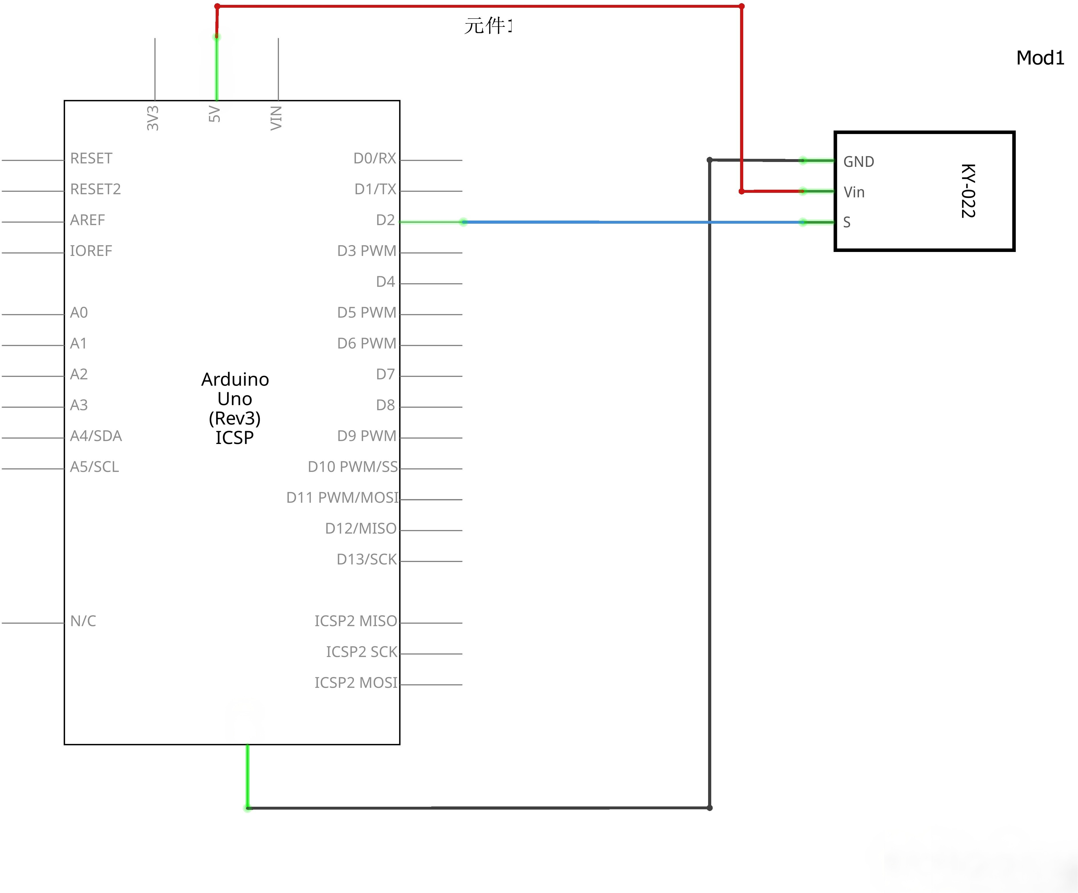
¶ Wiring diagram
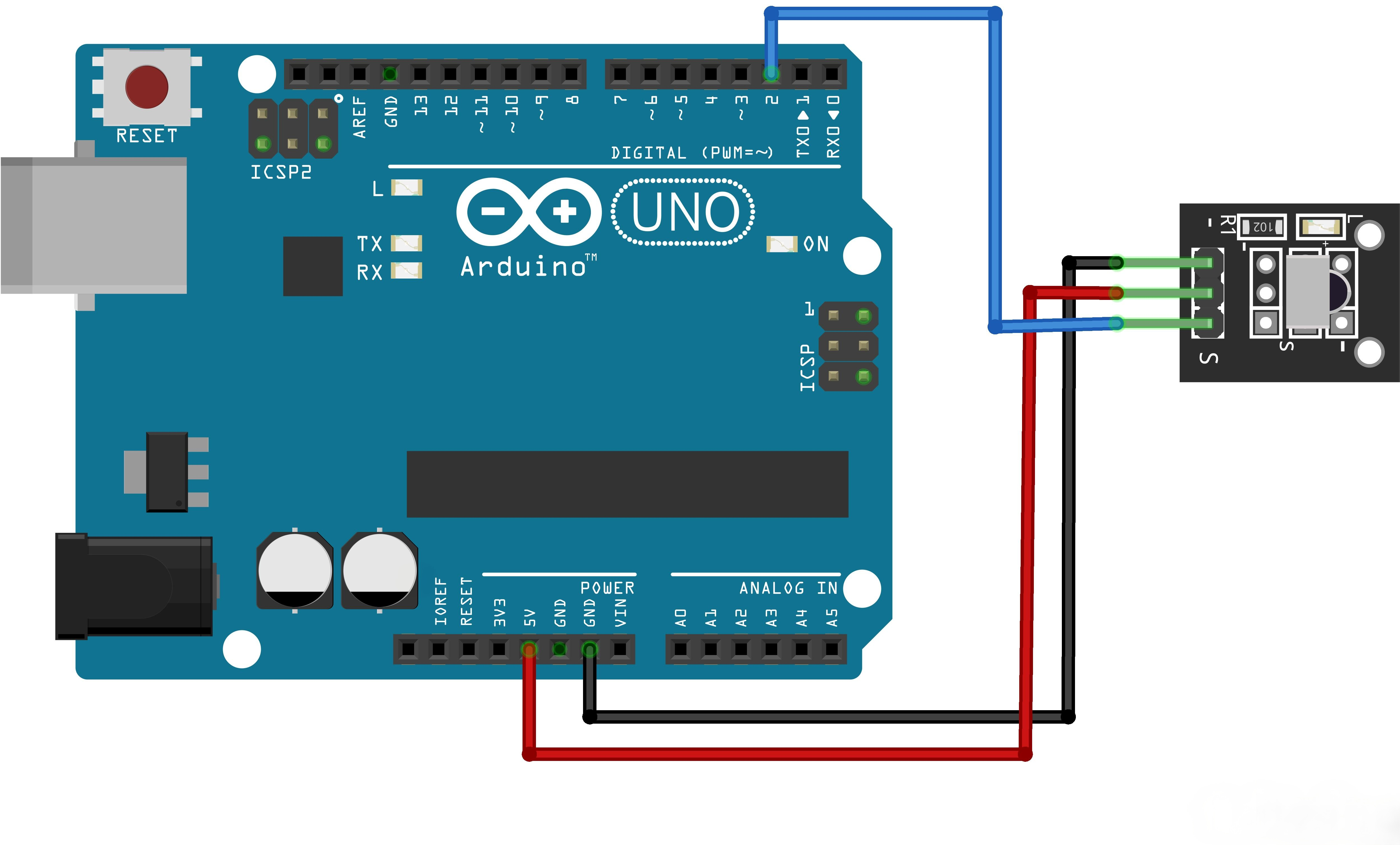
There are 3 connections to the IR Receiver.
The connections are: Signal, Voltage and Ground.
The“G”is the Ground,“Y”is signal, and“R”is Voltage 3.3V.
¶ Code
You can click the blue text link to download the program file to your local device, and double-click the file to open it after the download is complete. Please note: Before opening the file, ensure that you have installed the Arduino IDE development environment and completed the installation of relevant components such as the board support package and driver corresponding to the UNO development board. If you have any questions about this operation process, you can refer to the "part 1" chapter of the document for detailed guidance.
Click the Serial Monitor button to turn on the serial monitor. The basics about the serial monitor are introduced in details in tutorial 4 in part 2.
#include "IRremote.h"
#include "IR.h"IRrecv irrecv(RECEIVER); // create instance of 'irrecv'
decode_results results; // create instance of 'decode_results'void setup() {
Serial.begin(9600);
Serial.println("IR Receiver Button Decode");
irrecv.enableIRIn();
}
setup() Function:Initializes the IR receiver and serial communication.
#include "IRremote.h": Includes the IRremote library for infrared signal decoding#include "IR.h": Includes custom IR definitionsIRrecv irrecv(RECEIVER): Creates an IR receiver instance on the specified pindecode_results results: Creates a structure to store decoded resultsSerial.begin(9600): Starts serial communication at 9600 baud rateirrecv.enableIRIn(): Enables the IR receiver to start listening for signals
You may wonder: the setup() function and the definitions/declarations before it should specify the corresponding data pins (e.g., which pin the signal is connected to), yet no operations defining data pins can be seen in the main program. So where exactly are the data pins defined? After opening the program, you will find a header file named IR.h, where the definition of data pins is included.
#define RECEIVER 11
If you want to use other pins with the same function, simply change the pin number in this definition to the actual pin you are connecting to.
void loop()
{
int tmpValue;
if (irrecv.decode(&results)) // have we received an IR signal?
{
for (int i = 0; i < 23; i++)
{
if ((keyValue[i] == results.value) && (i<KEY_NUM))
{
Serial.println(keyBuf[i]);
tmpValue = results.value;
}
else if(REPEAT==i)
{
results.value = tmpValue;
}
}
irrecv.resume(); // receive the next value
}
}
loop() Function:Main loop that continuously receives and decodes IR signals.
if (irrecv.decode(&results)): Checks if an IR signal has been received and decodedfor (int i = 0; i < 23; i++): Loops through possible key valuesif ((keyValue[i] == results.value) && (i<KEY_NUM)): Matches the received value to a known keySerial.println(keyBuf[i]): Prints the corresponding key nametmpValue = results.value: Stores the current value for repeat handlingelse if(REPEAT==i): Handles repeat signalsirrecv.resume(): Resets the receiver to wait for the next signal
Alternative Implementation (Switch Case):
The implementation effect of the above program is the same as that of the following, but it is more concise:
// switch(results.value)
// {
// case 0xFFA25D: Serial.println("POWER"); break;
// case 0xFFE21D: Serial.println("FUNC/STOP"); break;
// case 0xFF629D: Serial.println("VOL+"); break;
// case 0xFF22DD: Serial.println("FAST BACK"); break;
// case 0xFF02FD: Serial.println("PAUSE"); break;
// case 0xFFC23D: Serial.println("FAST FORWARD"); break;
// case 0xFFE01F: Serial.println("DOWN"); break;
// case 0xFFA857: Serial.println("VOL-"); break;
// case 0xFF906F: Serial.println("UP"); break;
// case 0xFF9867: Serial.println("EQ"); break;
// case 0xFFB04F: Serial.println("ST/REPT"); break;
// case 0xFF6897: Serial.println("0"); break;
// case 0xFF30CF: Serial.println("1"); break;
// case 0xFF18E7: Serial.println("2"); break;
// case 0xFF7A85: Serial.println("3"); break;
// case 0xFF10EF: Serial.println("4"); break;
// case 0xFF38C7: Serial.println("5"); break;
// case 0xFF5AA5: Serial.println("6"); break;
// case 0xFF42BD: Serial.println("7"); break;
// case 0xFF4AB5: Serial.println("8"); break;
// case 0xFF52AD: Serial.println("9"); break;
// case 0xFFFFFFFF: Serial.println(" REPEAT");break;
// default:
// Serial.println(" other button ");
// }// End Case
Switch Case Implementation:
- Uses switch-case statements to map decoded IR values to button names
- Supports a wide range of standard remote control buttons including:
- Power, function/stop, volume control
- Navigation buttons (up, down, fast forward, fast back)
- Numeric keys (0-9)
- Special functions (EQ, ST/REPT)
- Repeat signal handling
IRremote Library:
This code uses the IRremote library, which simplifies the process of receiving and decoding infrared signals. The library handles the low-level timing and protocol decoding, allowing you to focus on the application logic.
Serial Monitor Output:
When a button is pressed on the remote control, the corresponding button name will be printed to the serial monitor. This makes it easy to debug and identify the codes for different buttons.
Repeat Signal Handling:
The code includes special handling for repeat signals (0xFFFFFFFF), which are sent when a button is held down. This allows for continuous input when a button is pressed and held.