¶ LCD 1602
¶ Overview
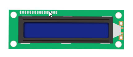
In this tutorial , you will learn how to wire up and use an alphanumeric LCD display. The display has an LED backlight and can display two rows with up to 16 characters on each row. You can see the rectangles for each character on the display and the pixels that make up each character. The display is just white and blue and is intended for showing text.
In this tutorial, we will run the Arduino example program for the LCD library.
¶ Component Required:
(1) x LCD1602 module
(1) x Potentiometer (10k)
(1) x 830 tie-points Breadboard
(16) x M-M wires (Male to Male jumper wires)
¶ Component Introduction
¶ LCD1602
VSS : A pin that connects to ground.
VDD: A pin that connects to a +5V power supply.
VO: A pin that adjust the contrast of LCD1602.
RS: A register select pin that controls where in the LCD’s memory you are writing data to. You can select either the data register, which holds what goes on the screen, or an instruction register, which is where the LCD’s controller looks for instructions on what to do next.
R/W: A Read/Write pin that selects reading mode or writing mode
E: An enabling pin that, when supplied with low-level energy, causes the LDC module to execute relevant instructions.
E: An enabling pin that, when supplied with low-level energy, causes the LDC module to execute relevant instructions.
D0-D7:Pins that read and write data.
A and K: Pins that control the LED backlight.
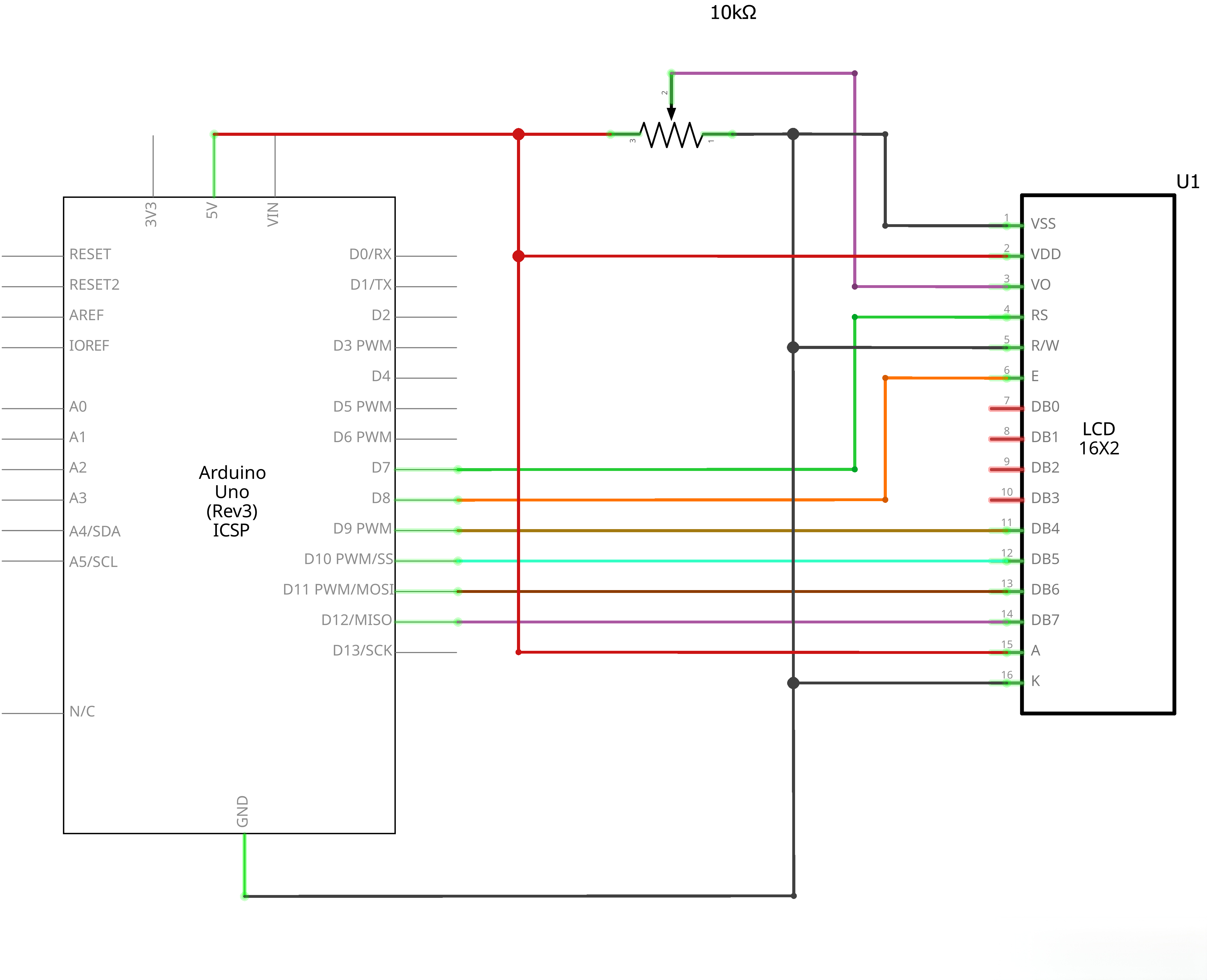
¶ Connection Schematic
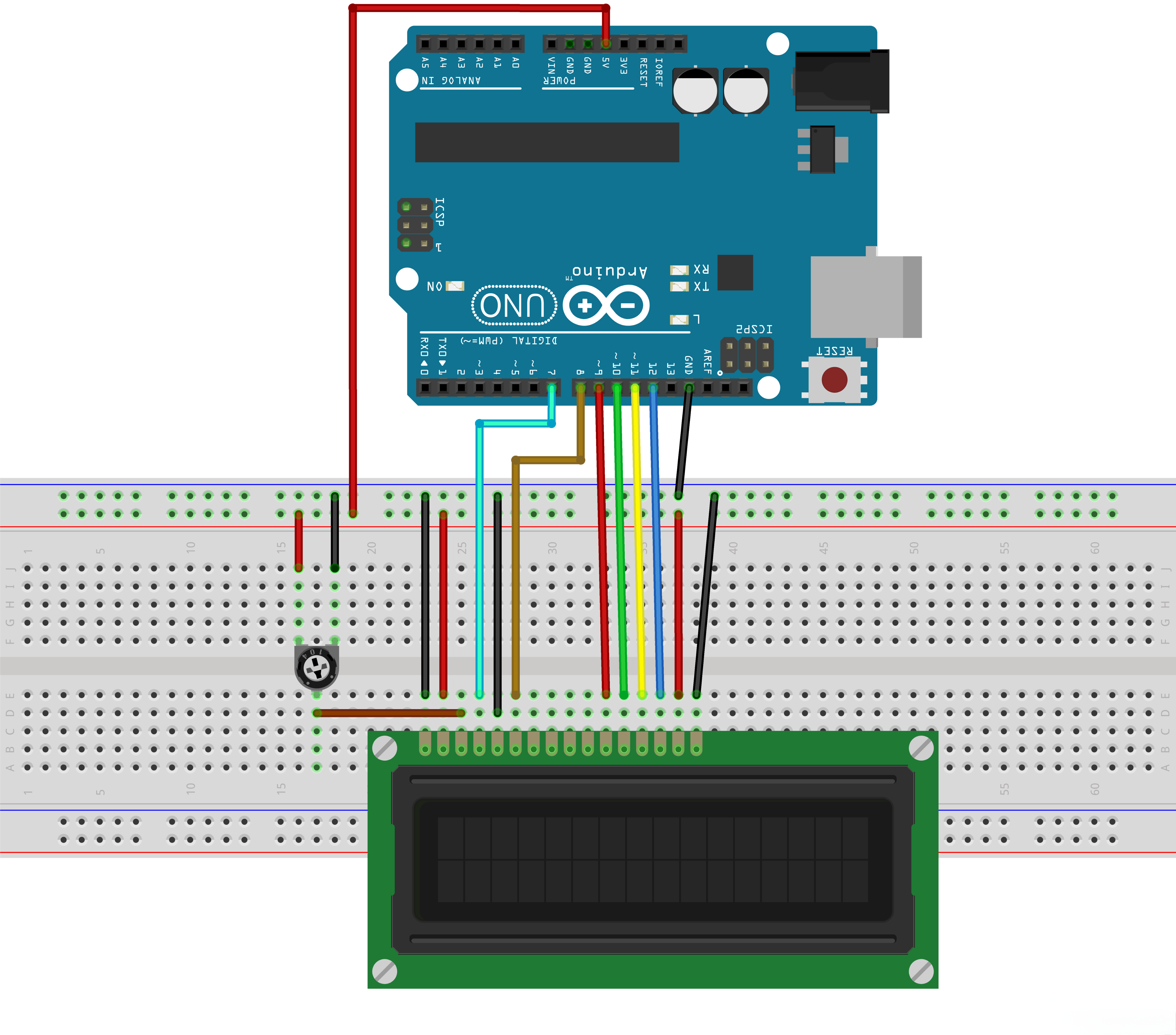
¶ Wiring diagram
¶ Code
You can click the blue text link to download the program file to your local device, and double-click the file to open it after the download is complete. Please note: Before opening the file, ensure that you have installed the Arduino IDE development environment and completed the installation of relevant components such as the board support package and driver corresponding to the UNO R3. If you have any questions about this operation process, you can refer to the "part 1" chapter of the document for detailed guidance.
Click the Serial Monitor button to turn on the serial monitor. The basics about the serial monitor are introduced in details in tutorial 4 in part 2.
// include the library code:
#include <LiquidCrystal.h>// initialize the library with the numbers of the interface pins
LiquidCrystal lcd(7, 8, 9, 10, 11, 12);
Includes and Initialization:
#include <LiquidCrystal.h>:Includes the LiquidCrystal library for LCD controlLiquidCrystal lcd(7, 8, 9, 10, 11, 12);:Creates LiquidCrystal object with specified pins (RS, Enable, D4, D5, D6, D7)
void setup() {
// set up the LCD's number of columns and rows:
lcd.begin(16, 2);
// Print a message to the LCD.
lcd.print("Hello, World!");
}
Setup Function:
lcd.begin(16, 2);:Initializes the LCD with 16 columns and 2 rowslcd.print("Hello, World!");:Prints "Hello, World!" to the LCD
void loop() {
// set the cursor to column 0, line 1
// (note: line 1 is the second row, since counting begins with 0):
lcd.setCursor(0, 1);
// print the number of seconds since reset:
lcd.print(millis() / 1000);
}
Loop Function:
lcd.setCursor(0, 1);:Sets the cursor to column 0, line 1 (second row)lcd.print(millis() / 1000);:Prints the number of seconds since reset
¶ Troubleshooting
- LCD Not Displaying:Check connections between Arduino and LCD
- Incorrect Characters:Verify pin connections match the LiquidCrystal initialization
- Dim Display:Adjust the contrast potentiometer (VO pin)
- No Text:Ensure the LCD is properly powered and the backlight is on
- Wiring Issues:Double-check all connections according to the circuit diagram
¶ Pin Connections
| Arduino Pin | LCD Pin | Function |
|---|---|---|
| Digital 7 | RS | Register Select |
| Digital 8 | Enable | Enable |
| Digital 9 | D4 | Data bit 4 |
| Digital 10 | D5 | Data bit 5 |
| Digital 11 | D6 | Data bit 6 |
| Digital 12 | D7 | Data bit 7 |
| GND | R/W | Read/Write (grounded for write-only) |
| GND | VSS | Ground |
| 5V | VCC | Power |
| Potentiometer | VO | Contrast adjustment |