¶ Eight_LED_with_74HC595_Flash_LED
¶ Overview
In this lesson, you will learn how to use eight large red LEDs with an ESP32 without needing to give up 8 output pins!
Although you could wire up eight LEDs each with a resistor to an ESP32 pin, you would rapidly start to run out of pins on your ESP32. If you don't have a lot of stuff connected to your ESP32. It's OK to do so - but often times we want buttons, sensors, servos, etc. and before you know it you've got no pins left. So, instead of doing that, you are going to use a chip called the 74HC595 .
Serial to Parallel Converter. This chip has eight outputs (perfect) and three inputs that you use to feed data into it a bit at a time.
This chip makes it a little slower to drive the LEDs (you can only change the LEDs about 500,000 times a second instead of 8,000,000 a second) but it's still really fast, way faster than humans can detect, so it's worth it!
¶ Component Required:
(1) x Elegoo ESP32
(2) x 400 tie-points breadboard
(8) x LED
(8) x 220 ohm resistors
(1) x 74hc595 IC
(16) x M-M wires (Male to Male jumper wires)
¶ Component Introduction
¶ 74HC595 Shift Register:
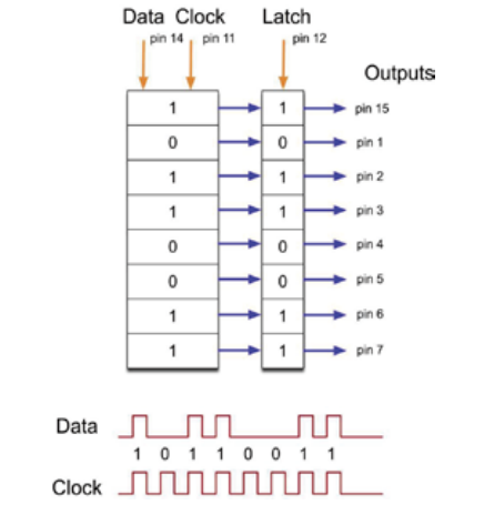
The shift register is a type of chip that holds what can be thought of as eight memory locations, each of which can either be a 1 or a 0. To set each of these values on or off, we feed in the data using the 'Data' and 'Clock' pins of the chip.
The clock pin needs to receive eight pulses. At each pulse, if the data pin is high, then a 1 gets pushed into the shift register; otherwise, a 0. When all eight pulses have been received, enabling the 'Latch' pin copies those eight values to the latch register. This is necessary; otherwise, the wrong LEDs would flicker as the data is being loaded into the shift register.
The chip also has an output enable (OE) pin, which is used to enable or disable the outputs all at once.
You could attach this to a PWM-capable GPIO pin and use 'analogWrite' to control the brightness of the LEDs. This pin is active low, so we tie it to GND.
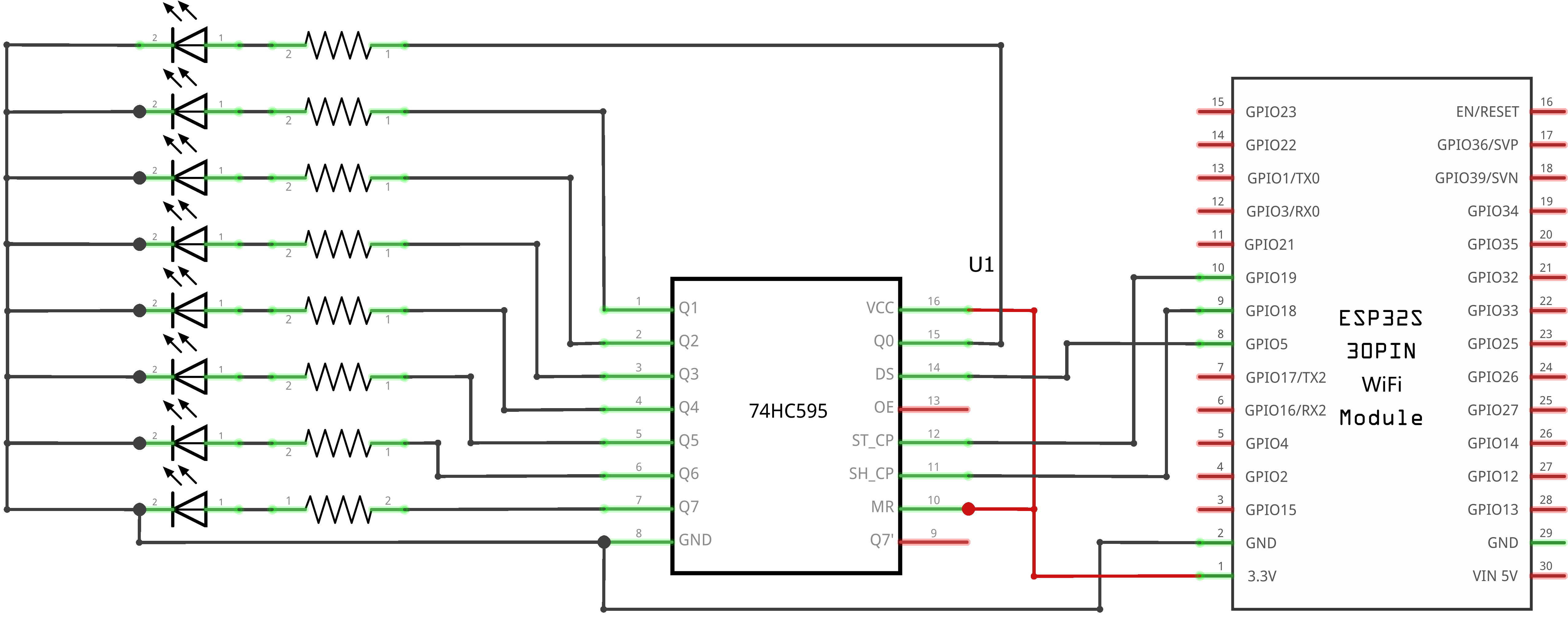
¶ Connection Schematic
¶ Wiring diagram
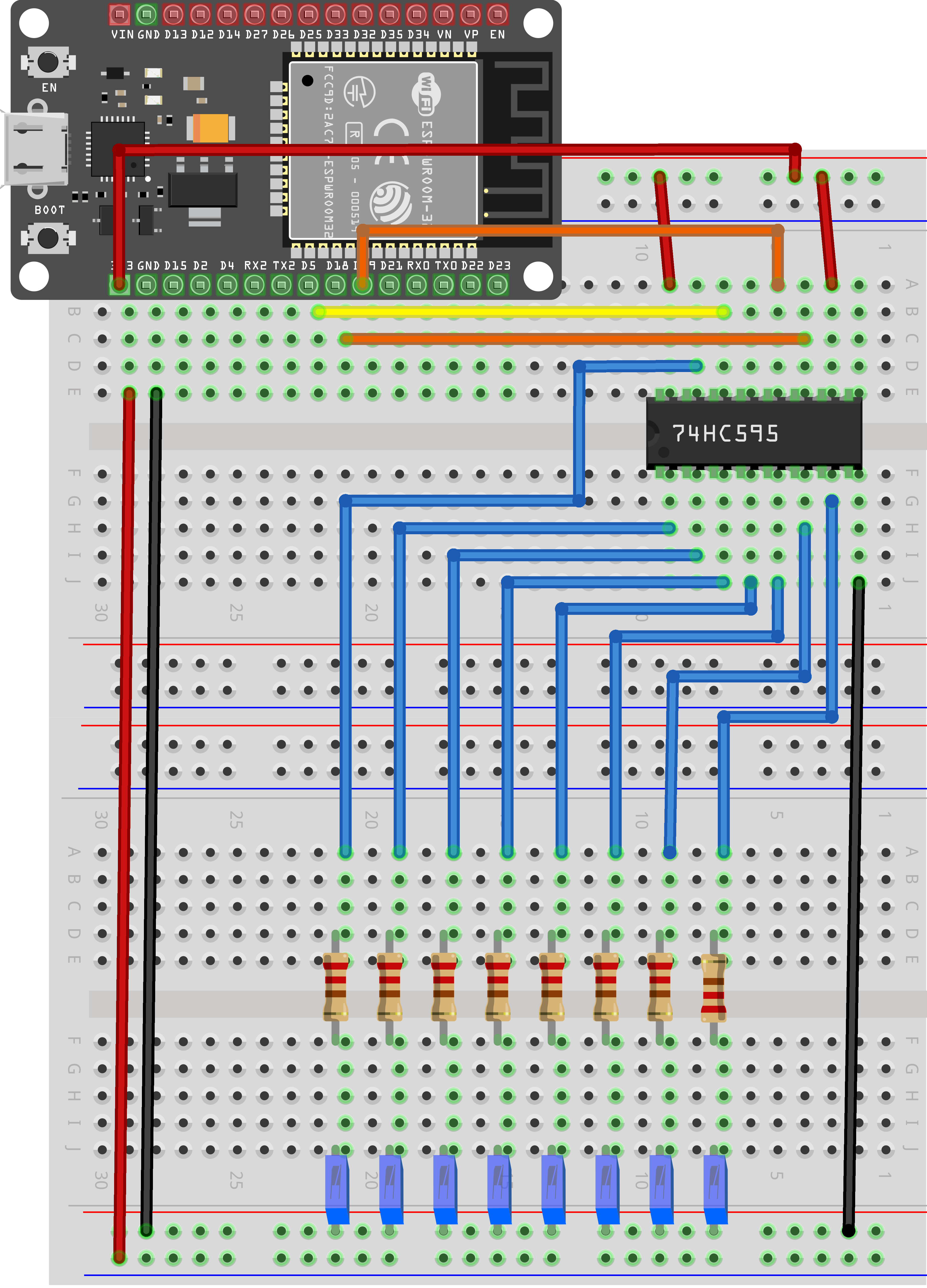
As we have eight LEDs and eight resistors to connect, there are actually quite a few connections to be made.
It is probably easiest to put the 74HC595 chip in first, as pretty much everything else connects to it. Put it so that the little U-shaped notch is towards the top of the breadboard. Pin 1 of the chip is to the left of this notch.
GPIO 5 from the ESP32 goes to pin #14 of the shift register
GPIO 19 from the ESP32 goes to pin #12 of the shift register
GPIO 18 from the ESP32 goes to pin #11 of the shift register
All but one of the outputs from the IC is on the left side of the chip. Hence, for ease of connection, that is where the LEDs are, too.
After the chip, put the resistors in place. You need to be careful that none of the leads of the resistors are touching each other. You should check this again before you connect the power to your ESP32.
If you find it difficult to arrange the resistors without their leads touching, then it helps to shorten the leads so that they are lying closer to the surface of the breadboard.
Next, place the LEDs on the breadboard. The longer positive LED leads must all be towards the chip, whichever side of the breadboard they are on.
Attach the jumper leads as shown above. Do not forget the one that goes from pin 8 of the IC to the GND column of the breadboard.
Load up the sketch listed a bit later and try it out. Each LED should light in turn until all the LEDs are on, and then they all go off and the cycle repeats.
¶ Code
You can click the blue text link to download the program file to your local device, and double-click the file to open it after the download is complete. Please note: Before opening the file, ensure that you have installed the Arduino IDE development environment and completed the installation of relevant components such as the board support package and driver corresponding to the ESP32 development board. If you have any questions about this operation process, you can refer to the "part 1" chapter of the document for detailed guidance.eight_led_with_74hc595_flash_led.ino
int tDelay = 100;
int latchPin = 19; // (19) ST_CP [RCK] on 74HC595
int clockPin = 18; // (18) SH_CP [SCK] on 74HC595
int dataPin = 5; // (5) DS [S1] on 74HC595byte leds = 0;
Variable and Hardware Configuration:
int tDelay = 100: Defines the delay time (in milliseconds) between LED changesint latchPin = 19: Defines the latch pin (GPIO 19) connected to 74HC595's ST_CP (RCK) pinint clockPin = 18: Defines the clock pin (GPIO 18) connected to 74HC595's SH_CP (SCK) pinint dataPin = 5: Defines the data pin (GPIO 5) connected to 74HC595's DS (S1) pinbyte leds = 0: Declares a byte variable to store the LED states (8 bits, 1 for each LED)
Shift Register Pin Definitions:
- ST_CP (RCK): Storage register clock input (latch pin)
- SH_CP (SCK): Shift register clock input
- DS (S1): Serial data input
- Q0-Q7: Parallel data outputs (connected to LEDs)
- OE: Output enable (usually grounded to enable outputs)
- MR: Master reset (usually connected to VCC to disable reset)
/* The most common method of using 74CH595
- lctchPin->LOW : Begin transmitting signals.
- shiftOut(dataPin, clockPin, bitOrder, value)
- dataPin: the pin on which to output each bit. Allowed data types: int.
- clockPin: the pin to toggle once the dataPin has been set to the correct value. Allowed data types: int.
- bitOrder: which order to shift out the bits; either MSBFIRST or LSBFIRST. (Most Significant Bit First, or, Least Significant Bit First).
- value: the data to shift out. Allowed data types: byte.
- lctchPin->HIch : The end of the transmission signal.
*/
void updateShiftRegister()
{
digitalWrite(latchPin, LOW);
shiftOut(dataPin, clockPin, LSBFIRST, leds);
digitalWrite(latchPin, HIGH);
}
updateShiftRegister() Function:Sends the LED state data to the 74HC595 shift register.
digitalWrite(latchPin, LOW): Sets the latch pin LOW to prepare for data transmissionshiftOut(dataPin, clockPin, LSBFIRST, leds): Shifts out the 8 bits of data from theledsvariableLSBFIRST: Least Significant Bit First - sends the rightmost bit firstleds: The byte containing the LED states
digitalWrite(latchPin, HIGH): Sets the latch pin HIGH to latch (store) the data in the output register
shiftOut() Function:
- Built-in Arduino function for serial data output
- Automatically handles the clock signal timing
- Supports both MSBFIRST and LSBFIRST bit orders
- Shifts 8 bits of data one bit at a time
void setup()
{
pinMode(latchPin, OUTPUT);
pinMode(dataPin, OUTPUT);
pinMode(clockPin, OUTPUT);
}
setup() Function:Initializes the system by configuring the GPIO pins.
pinMode(latchPin, OUTPUT): Sets the latch pin as an outputpinMode(dataPin, OUTPUT): Sets the data pin as an outputpinMode(clockPin, OUTPUT): Sets the clock pin as an output
void loop()
{
//Turn off all led
leds = 0;
updateShiftRegister();
delay(tDelay);
//Create a for loop:i 0 through 7 have gradually increased
for (int i = 0; i < 8; i++)
{
//turn on the led with the i transform
bitSet(leds, i);
updateShiftRegister();
delay(tDelay);
}
}
loop() Function Overview:The main loop that creates the chasing LED effect by sequentially turning on LEDs.
1. LED Initialization Module:
//Turn off all led
leds = 0;
updateShiftRegister();
delay(tDelay);
leds = 0: Sets all bits to 0, which will turn off all LEDsupdateShiftRegister(): Sends the all-off state to the shift registerdelay(tDelay): Waits for the specified delay time before continuing
2. LED Sequencing Module:
//Create a for loop:i 0 through 7 have gradually increased
for (int i = 0; i < 8; i++)
{
//turn on the led with the i transform
bitSet(leds, i);
updateShiftRegister();
delay(tDelay);
}
- For Loop: Iterates from 0 to 7 (for all 8 LEDs)
- bitSet(leds, i): Sets the ith bit in the
ledsvariable to 1, which turns on the corresponding LED- Example:
bitSet(leds, 0)turns on the first LED - Example:
bitSet(leds, 7)turns on the eighth LED
- Example:
- updateShiftRegister(): Sends the updated LED state to the shift register
- delay(tDelay): Waits for the specified delay time before moving to the next LED
Bitwise Operations:
bitSet(variable, bit): Sets the specified bit to 1- In this code, each bit in the
ledsbyte corresponds to one LED - Example:
leds = 0b00000001turns on only the first LED - Example:
leds = 0b10000001turns on the first and eighth LEDs
LED Chasing Effect:
- The LEDs light up one by one from the first to the eighth
- After all LEDs are on, the loop restarts by turning all LEDs off and repeating the sequence
- The speed of the effect is controlled by the
tDelayvariable
Troubleshooting Tips:
- LEDs not lighting up: Check power supply, ground connections, and resistor values
- Wrong LED sequence: Verify bit order (LSBFIRST vs MSBFIRST) in the shiftOut function
- Flickering LEDs: Ensure proper decoupling capacitors and stable power supply
- All LEDs on at once: Check latch pin timing and connections
Extending the Circuit:
- Multiple 74HC595 chips can be daisy-chained to control more than 8 outputs
- The Q7' (serial output) pin connects to the DS pin of the next chip
- Only 3 GPIO pins are needed regardless of the number of shift registers
Bit Order Considerations:
- LSBFIRST: Least Significant Bit First - Q0 is the first bit sent
- MSBFIRST: Most Significant Bit First - Q7 is the first bit sent
- The choice affects the LED numbering sequence
Alternative Implementation:
- The code can be modified to create different LED patterns
- Example: Alternating LEDs (0b01010101)
- Example: Binary count display (count from 0 to 255)
- Example: Knight rider effect (LEDs chase back and forth)
This code provides a fundamental example of using shift registers to expand the output capabilities of microcontrollers, demonstrating both the hardware connections and the software implementation required.
Do not dismantle the project you built in this tutorial—it will be reused in the next .