¶ Two color LED
¶ Overview
In this experiment, we will learn how to use Dual-color Common-CathodeLED.
¶ Two-Color LED Module 5 mm
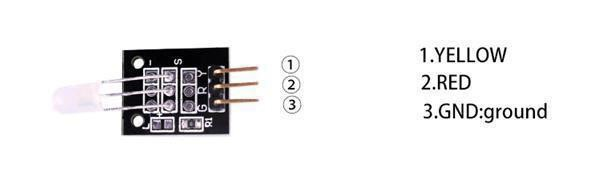
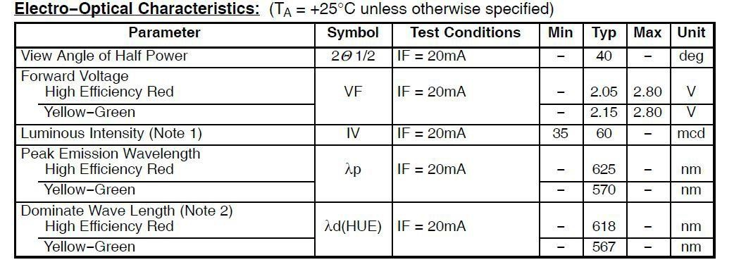
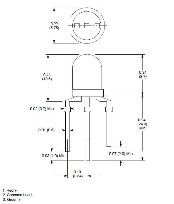
The 5 mm LED has a common cathode connected to the '-' pin on the PCB. The center pin connects to the red anode and the 'S' pin connects to the green anode. No resistor in series is included in circuit.A suitable value of resistance for low voltage operation would be 220 ohms.
You can understand its working principle as follows: the color and brightness of this LED are controlled by two pins, R and Y, which stand for RED and Yellow respectively. The final displayed color is formed by mixing these two colors. You can also do some trial tests, such as connecting only the R pin and outputting a high level to check the color of the indicator light.
¶ Component Introduction
Dual-color Common-Cathodeled:
¶ Connection Schematic
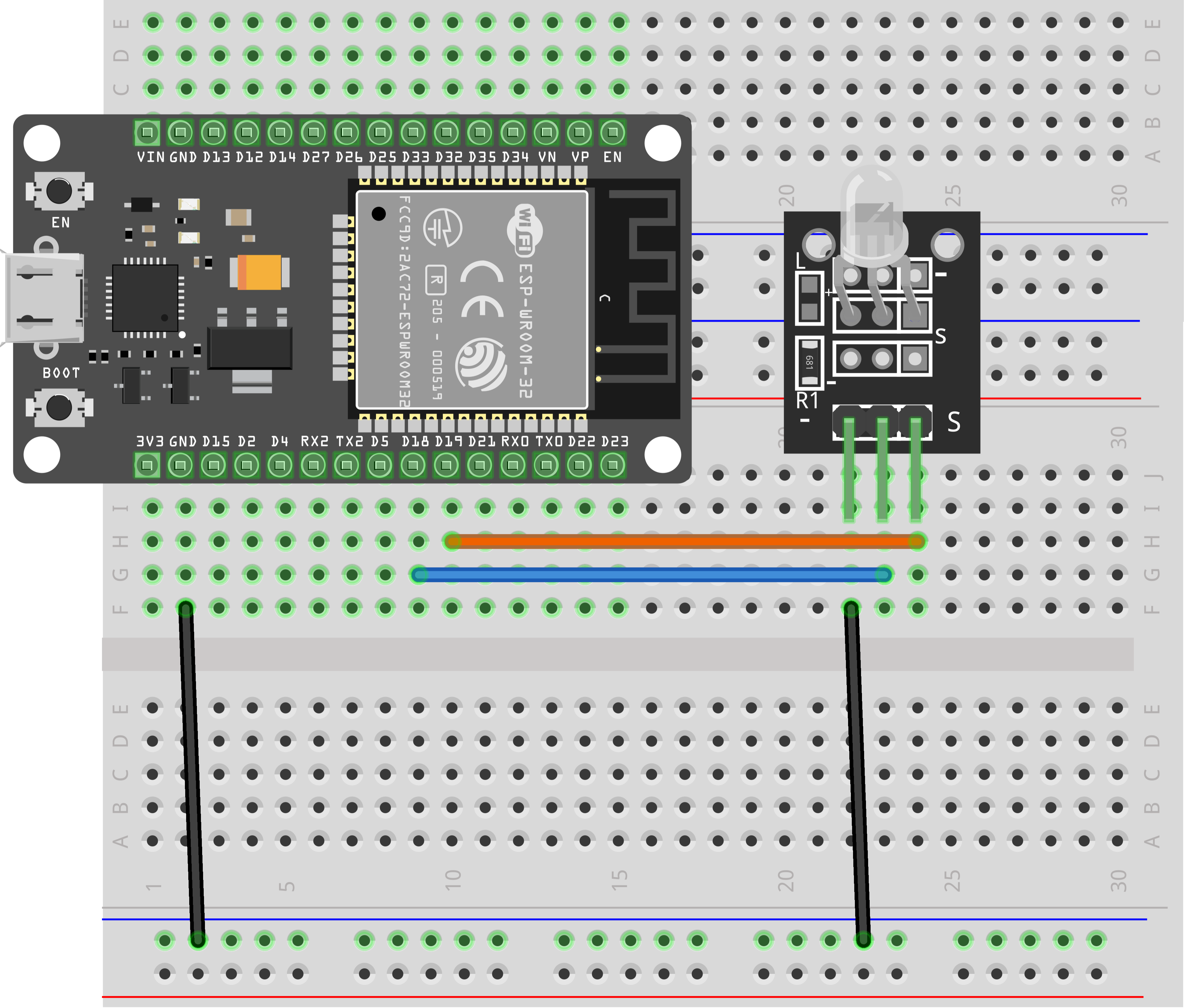
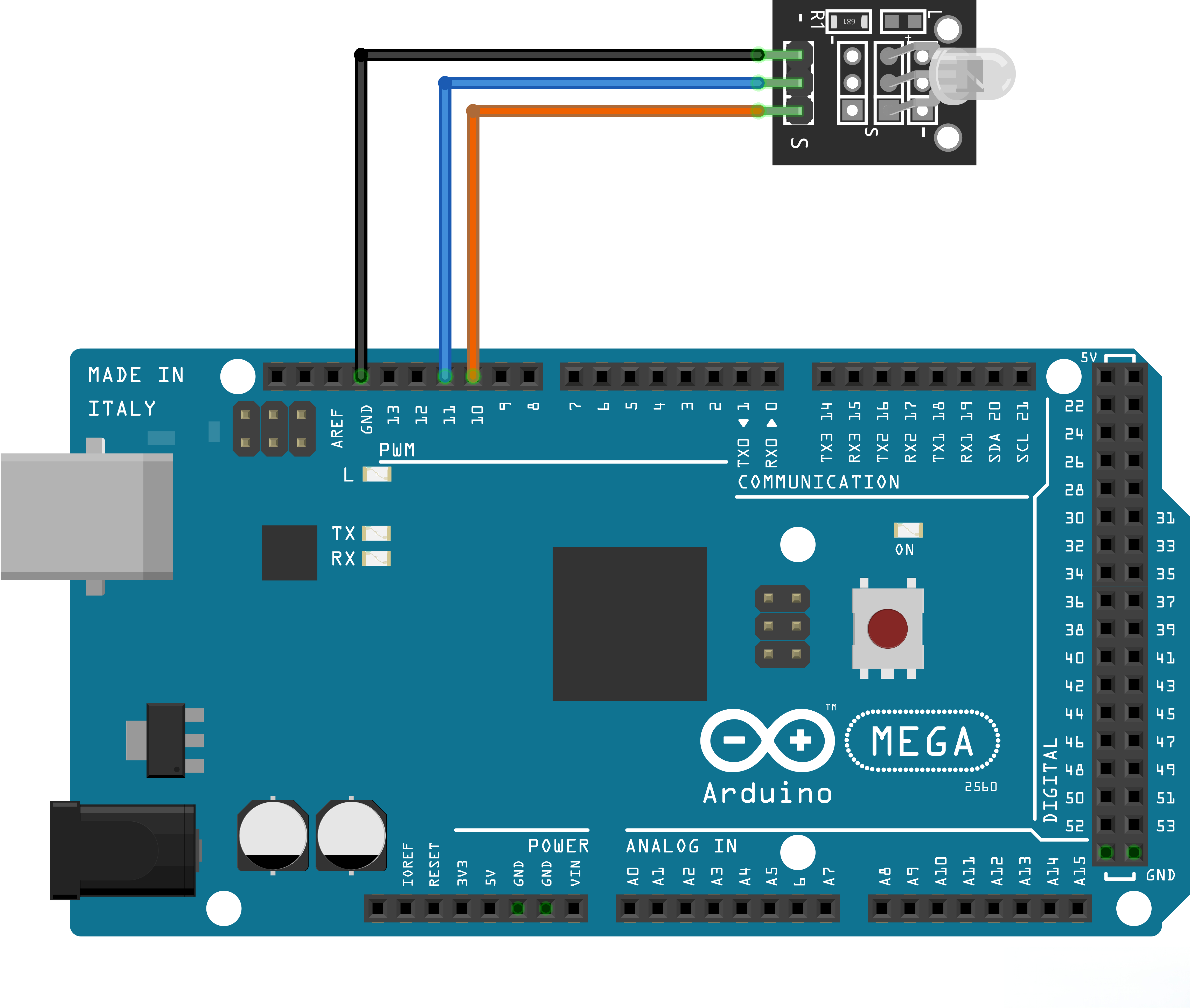
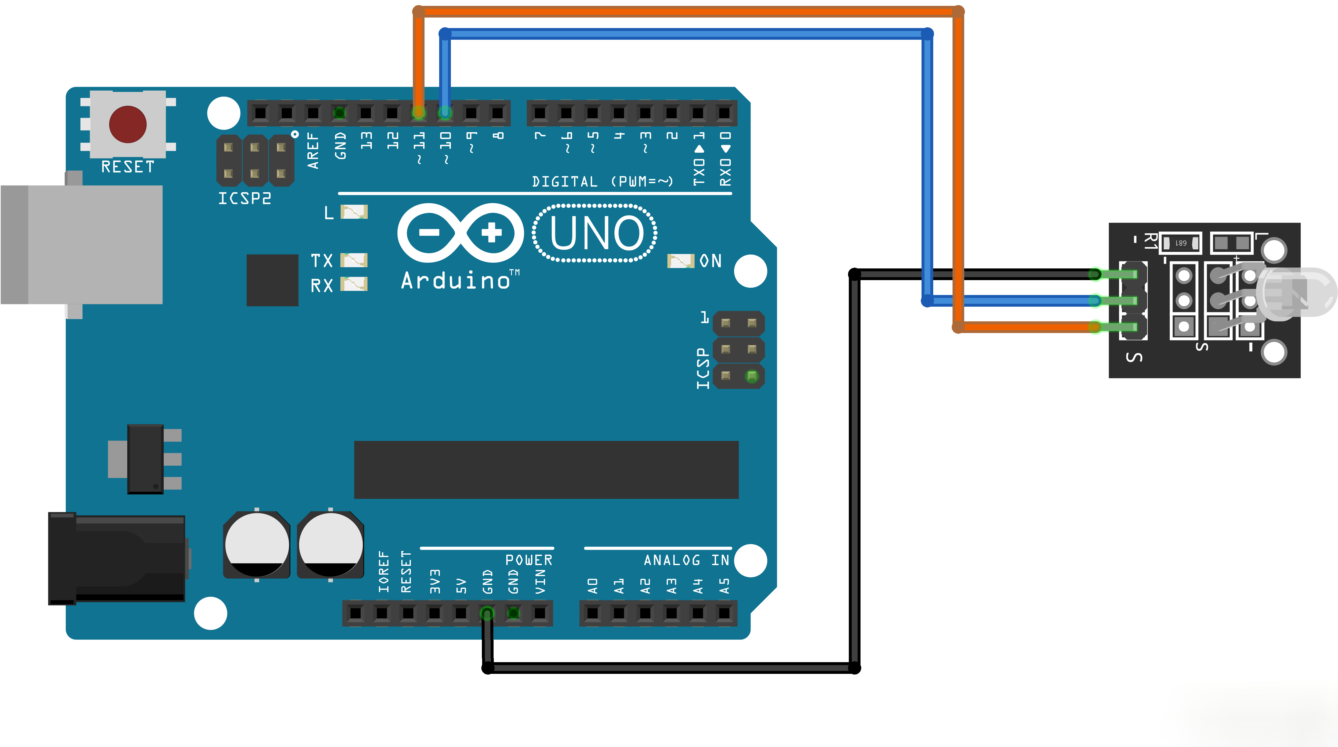
¶ Wiring diagram
¶ Code
You can click the blue text link to download the program file to your local device, and double-click the file to open it after the download is complete. Please note: Before opening the file, ensure that you have installed the Arduino IDE development environment and completed the installation of relevant components such as the board support package and driver corresponding to the board.
¶ Code Description
int redpin = 18; // select the pin for the red LED
int yellowpin =19; // select the pin for the yellowLED
int val;
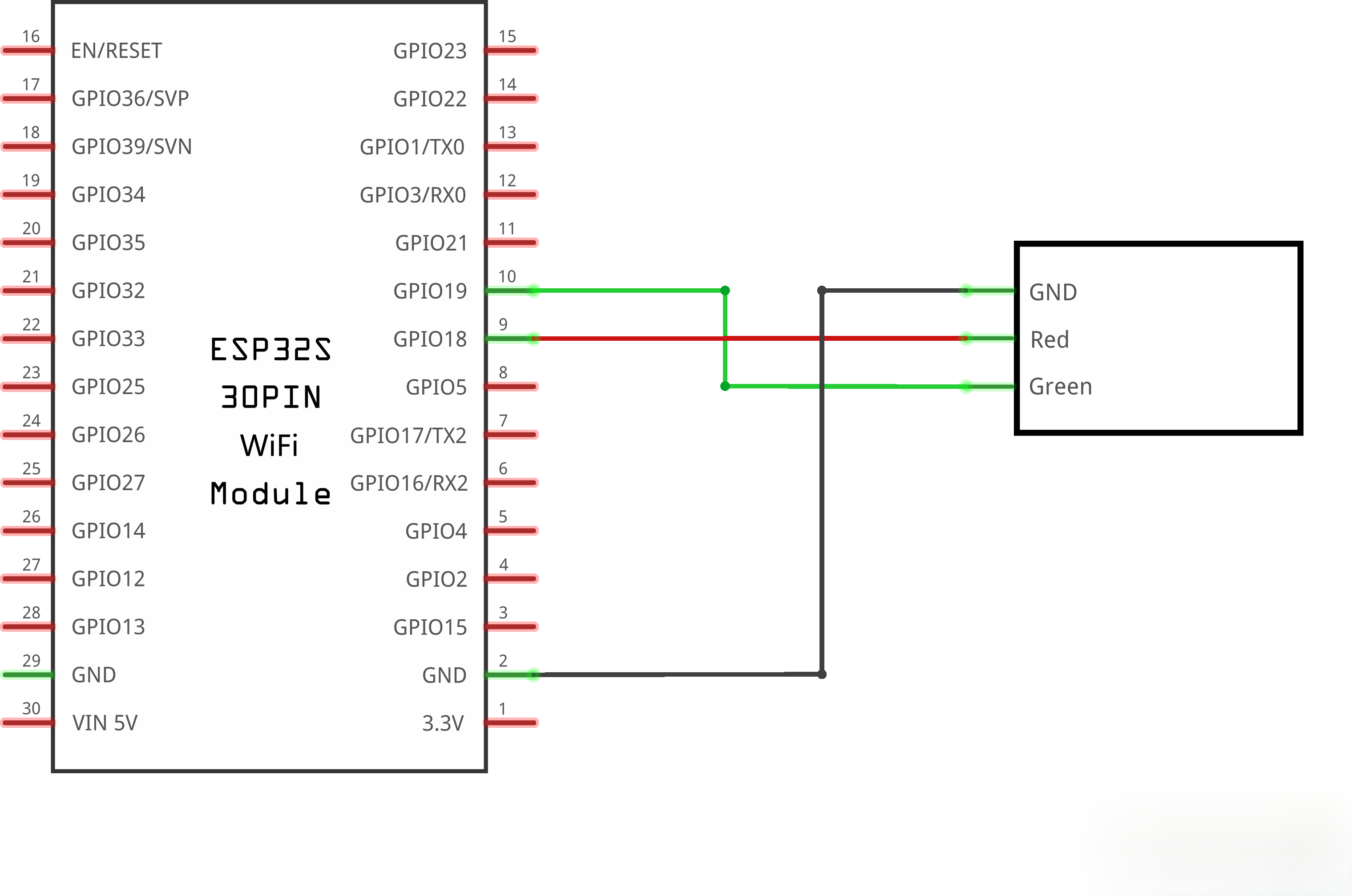
The RED pin and YELLOW pin are defined here, using GPIO18 and GPIO19 of ESP32 respectively. A variable is also defined to store the brightness value.If you are using other types of main control boards, you can change the pins to match your actual wiring. For UNO series boards, pins D10 and D11 are available options.
void setup()
{
pinMode(redpin, OUTPUT);
pinMode(yellowpin, OUTPUT);
Serial.begin(9600);
}
The relevant pins are set to output mode here, and the baud rate for serial communication is also configured.
void loop()
{for (val = 255; val > 0; val--)
{
analogWrite(redpin, val);
analogWrite(yellowpin, 255 - val);delay(15);}
for (val = 0; val < 255; val++)
{
analogWrite(redpin, val);
analogWrite(yellowpin, 255 - val);
delay(15);
}
Serial.println(val, DEC);
}
Two for loops are included in the loop function, differing only in the change rule of variable val. One decreases gradually from 255, while the other increases from 0 to 255, each looping 255 times corresponding to 255 brightness levels of the LED. Note the parameter changes inside analogWrite(). One channel value increases and the other decreases, which makes one color brighten gradually while the other fades synchronously.