¶ Photo-Interrupter
¶ Overview
In this experiment, we will learn how to use Photo-interrupter module.
¶ Light blocking
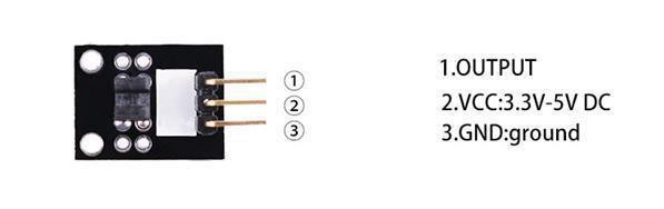
Slotted light barrier. The middle pin connects to + 5 V supply and the pin marked ‘-’ connects to
ground. The output signal (with a 10 K ohm pullup to +5 V) is available on the pin on the right.
¶ Component Introduction
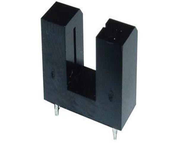
¶ Opto Interrupter Sensor:
¶ Principle
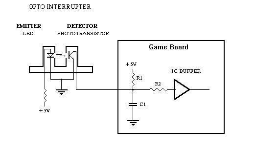
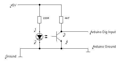
Note that the photo interrupter module is triggered only when an object blocks the gap in the middle of the module. Simply shielding ambient light cannot trigger the sensor.
Note: The photo interrupter module outputs a low level by default. It will output a high level when the middle gap is blocked by an object. You can judge whether the sensor is triggered according to the change of the level.
¶ Connection Schematic
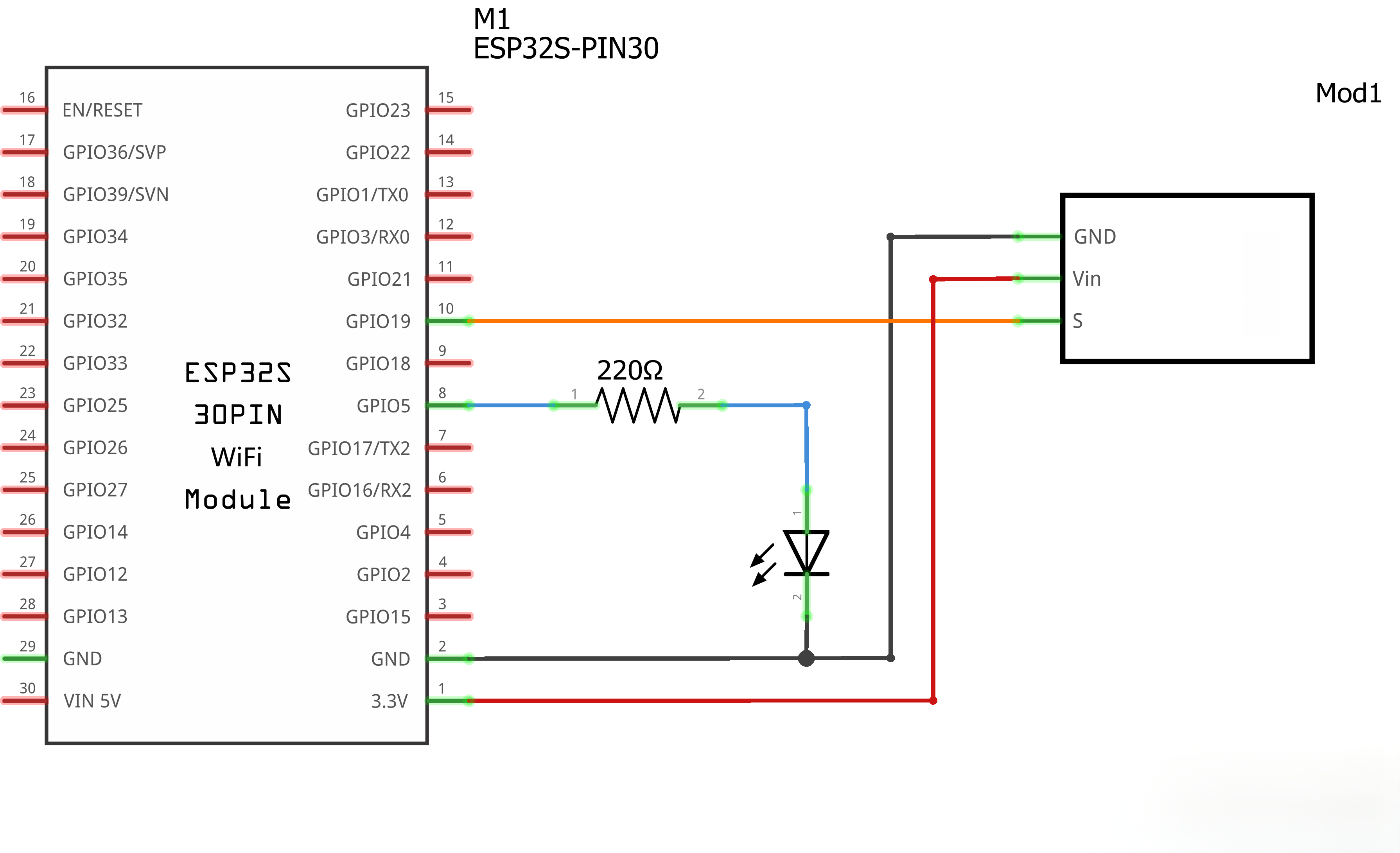
¶ Wiring Diagram
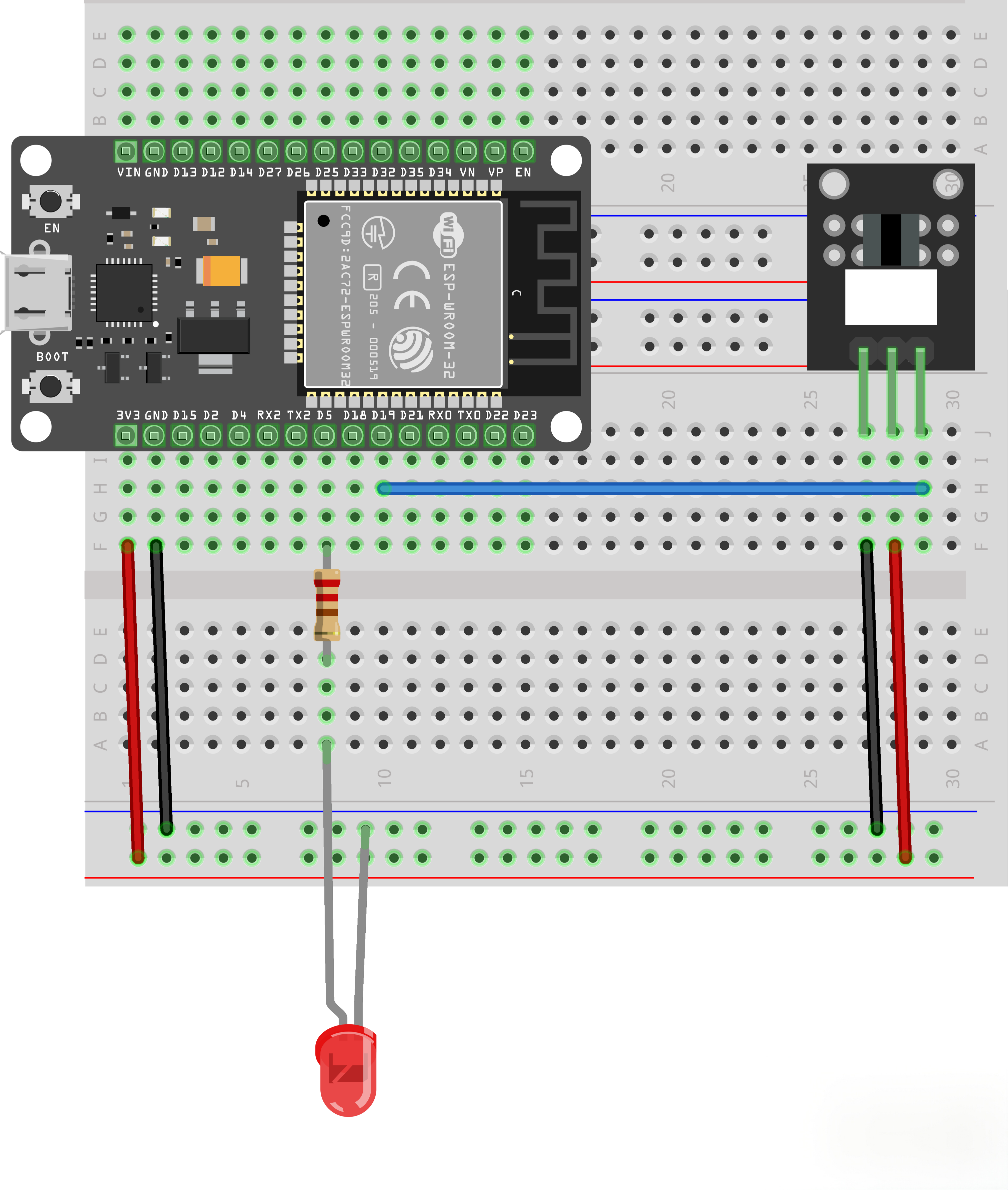
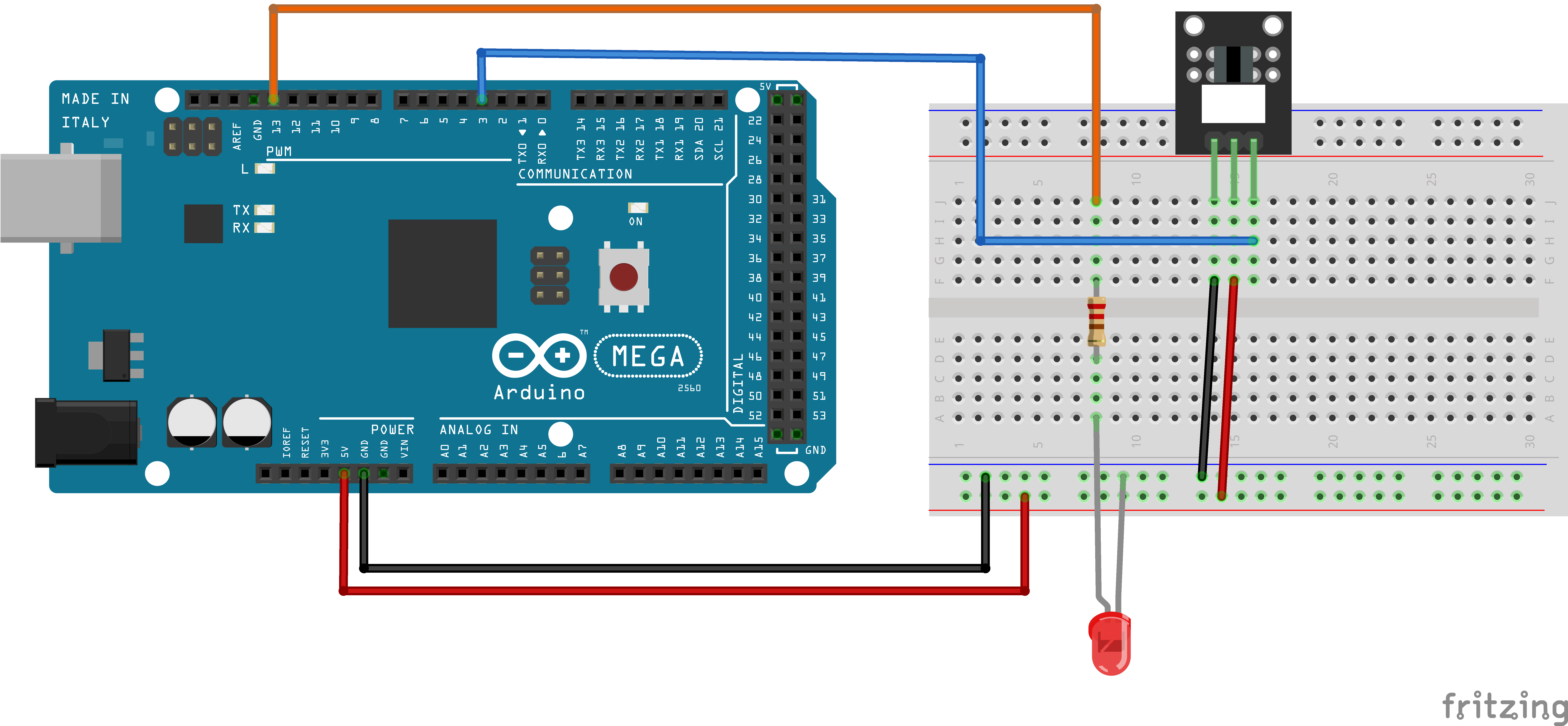
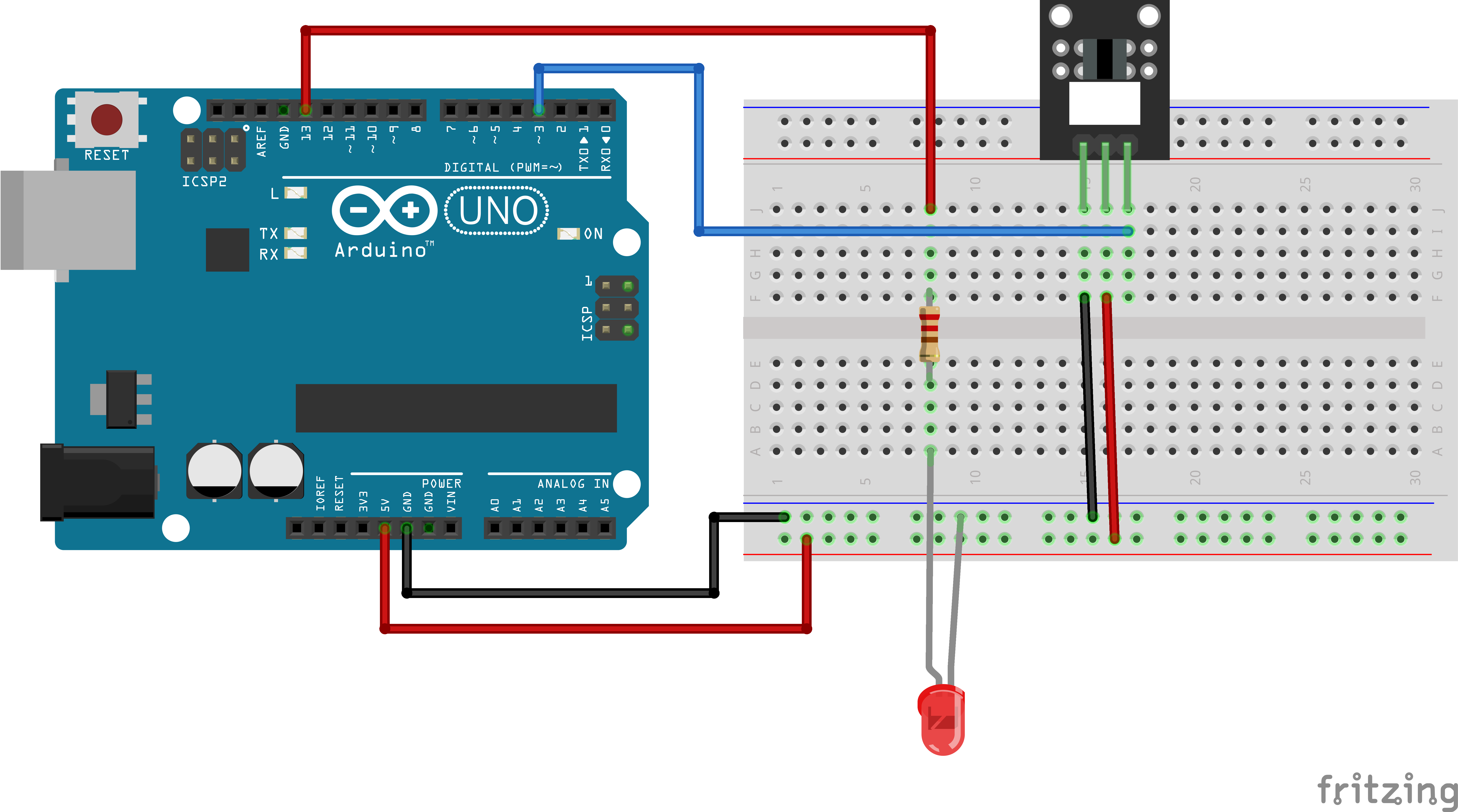
¶ Code
You can click the blue text link to download the program file to your local device, and double-click the file to open it after the download is complete. Please note: Before opening the file, ensure that you have installed the Arduino IDE development environment and completed the installation of relevant components such as the board support package and driver corresponding to the board.
int Led=5; //define the led's port
int buttonpin=19; //define the port of light blocking module
int val;//define digital variable val
Several pins and variables are defined here. This example adopts the pin configuration of ESP32. If you use other main control boards or different pins, please modify the pin numbers in the code to match your actual wiring.
void setup()
{pinMode(Led,OUTPUT);//define digital variable val
pinMode(buttonpin,INPUT);//define light blocking module as a output port
}
The pin modes are configured here: the LED pin is set to output mode, and the sensor pin is set to input mode.
void loop()
{ val=digitalRead(buttonpin);//read the value of the digital interface 3 assigned to valif(val==HIGH) //when the light blocking sensor have signal, LED blink
{
digitalWrite(Led,HIGH);
}
else
{
digitalWrite(Led,LOW);
}
}
The sensor transmits digital signals, so we use the digitalRead() function to read the pin level signal and assign it to a variable which stores the output state of the sensor. Afterwards, we judge the level of this variable through the if statement. If the sensor outputs a high level, it means the sensor is triggered and the LED lights up; otherwise, the LED turns off.