¶ Led Matrix
One of the board’s key features is an 8×13 blue LED matrix that is managed by the STM32 microcontroller of the UNO Q.
This tutorial demonstrates projects using both official examples and custom examples to cover as many common scenarios as possible. You are free to further expand and modify the code based on these examples.
¶ Official Examples
Open Arduino App‑Lab, type matrix in the search bar, and locate the LED Matrix Painter exampleArduino

After opening the example, you are advised to read the README.md file first, which contains corresponding operation instructions and explanations and will not be repeated here. Open the sketch, select the .ino file, and click the RUN button to upload the program to UNO‑Q.
After running the .ino file, a control web page will pop‑up automatically (as shown in the figure below). You can set parameters such as the brightness and position of the dot‑matrix on this page.
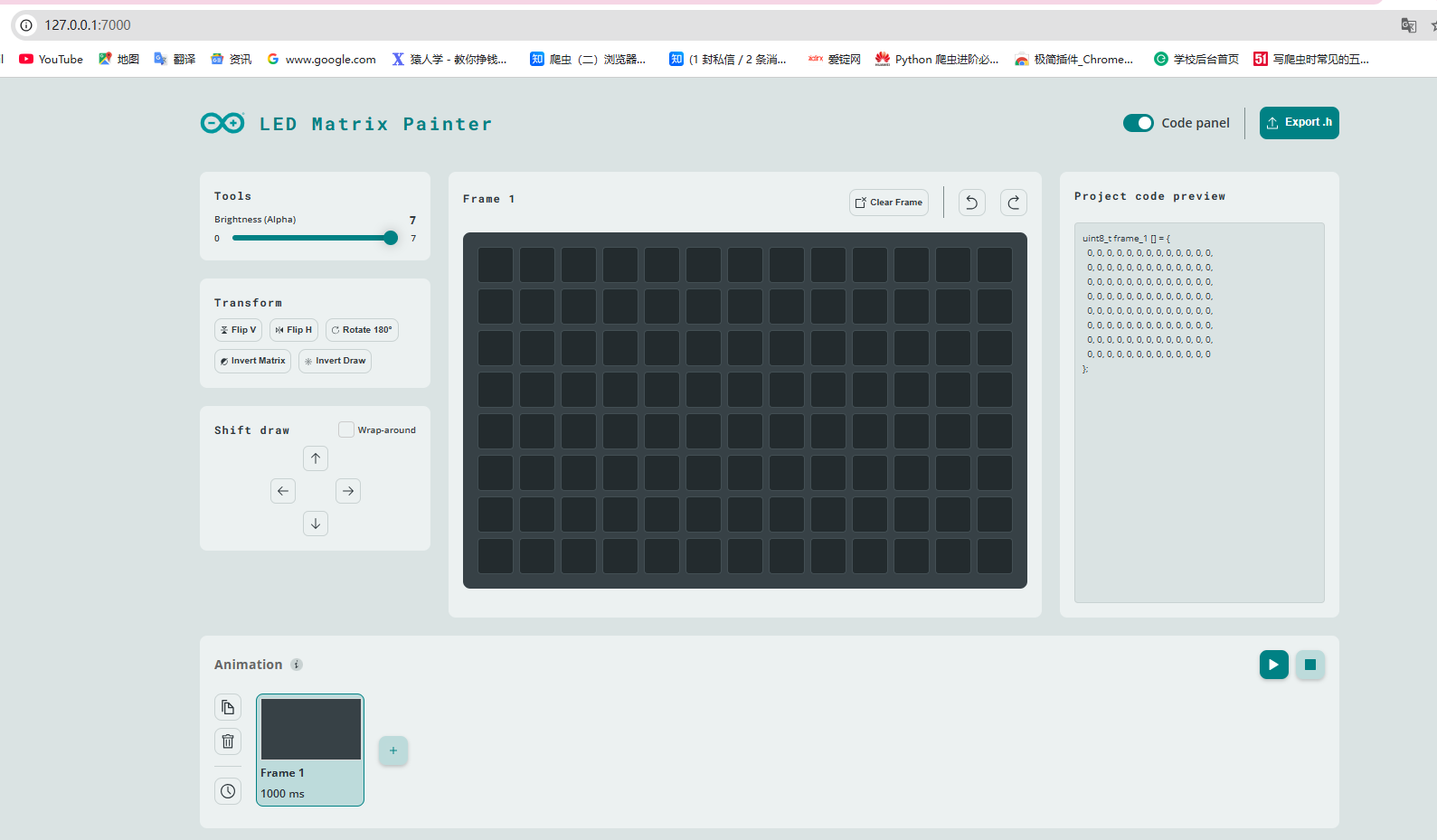
You can click on the black matrix area on the web page. The clicked area will light up, and the corresponding position on the UNO‑Q dot‑matrix screen will light up synchronously.
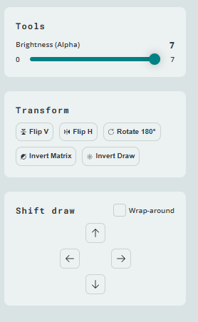
Some controls on this webpage are adjustable. Starting with the left panel: in the Tools section, drag the horizontal slider to adjust brightness, ranging from 0 to 7. The Transform section is used to set the image symmetry. Shift draw adjusts the displayed frame and supports shifting up, down, left and right. It is suitable for creating dynamic effects; feel free to test it out.
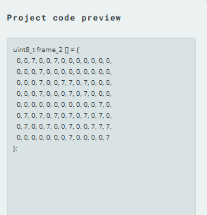
The right‑hand area displays the raw matrix data. Normally, the value is 1 for lit dots and 0 for off dots. Since the brightness is set to 7 here, the displayed value is 7. To customize the LED matrix effect, copy the data into the IDE and modify the values at corresponding positions.

¶ Arduino app lab
If you do not want to manually copy the dot matrix list into the IDE, which can be quite cumbersome, you can export the dot matrix to your local device and then import the file for subsequent operations.
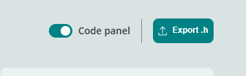

The exported .h file contains all your configured patterns, so you only need to export it once.
You can directly load the exported .h file into Arduino App Lab. The specific steps are as follows: after creating the app, load it as shown in the figure below.
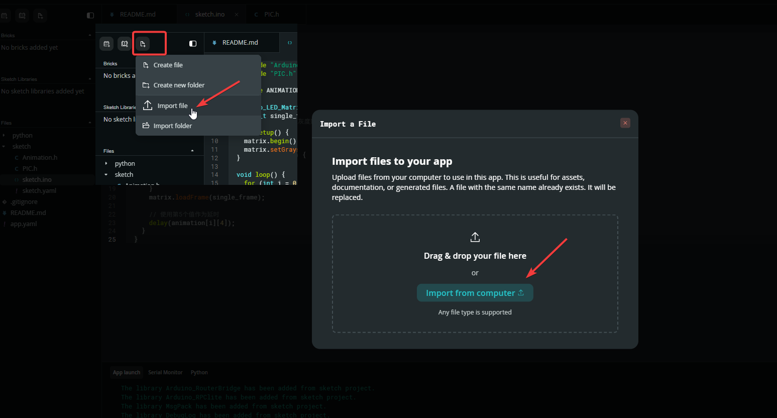
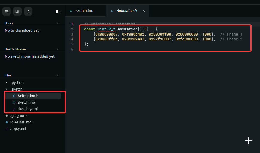
Click the sketch.ino file and paste the code below into it. Please check the header‑file import directive #include "Animation.h". Make sure the filename inside the quotes matches your exported file name. Modify it if necessary, then click Run.
#include "Arduino_LED_Matrix.h"
#include "Animation.h" // Original header file, keep as is

#define ANIMATION_FRAMES 2 // Number of frames

Arduino_LED_Matrix matrix;
uint32_t single_frame[4];

void setup() {
  matrix.begin();
  matrix.setGrayscaleBits(8); // Match the exported 8-bit grayscale data
}

void loop() {
  for (int i = 0; i < ANIMATION_FRAMES; i++) {
    // Copy the first 4 display data values, skip the 5th delay value
    for (int j = 0; j < 4; j++) {
      single_frame[j] = animation[i][j];
    }
    matrix.loadFrame(single_frame);

    // Use the 5th value as the delay
    delay(animation[i][4]);
  }
}
¶ Arduino IDE
There are some programming differences between Arduino IDE and Arduino App Lab. The first is the data format. The exported .h file contains five parameters, while Arduino IDE only accepts 4‑bit data. You need to change the parameter count to 4 and remove the last parameter for delay (1000 ms in the example shown in the figure).
Before modification:
const uint32_t animation[][5] = {
    {0x00000007, 0xf0e0c402, 0x3030ff00, 0x00000000, 1000},  // Frame 1
    {0x0000ff0c, 0x0cc02401, 0x27f98007, 0xfe000000, 1000},  // Frame 2
};
After modification:
const uint32_t animation[][4] = {
    {0x00000007, 0xf0e0c402, 0x3030ff00, 0x00000000},  // Frame 1
    {0x0000ff0c, 0x0cc02401, 0x27f98007, 0xfe000000},  // Frame 2
};
Arduino IDE ino:
#include "Arduino_LED_Matrix.h"
#include "Animation.h" // Your header file

Arduino_LED_Matrix matrix;
const int animation_frames = 2;

void setup() {
  matrix.begin();
}

void loop() {
  for (int i = 0; i < animation_frames; i++) {
    matrix.loadFrame(animation[i]); // Pass a single frame's uint32_t array directly
    delay(500); // Frame switching delay, adjust as needed
  }
}
If no error occurs after upload but no pattern is displayed on the matrix, do not panic. This happens because Arduino IDE cannot locate the bootloader files required for compiling UNO Q, caused by framework issues. Simply re-burn the bootloader to fix it.
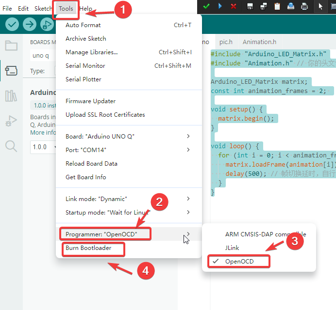
If you have multiple dot‑matrix patterns, change const int animation_frames = 2; in the code to your required frame count.
Compared with the online version, the offline version offers greater flexibility. You can combine both tools for future projects: draw patterns on the webpage and export them locally, which will save a great deal of time.