¶ Header
¶ Overview
In this experiment, we will learn how to use the light dependent resistor, also called photo resistor
module.
Light dependent resistor is very common in our daily life. it is mainly used in intelligent switch so as to bring convenience to our life. At the same time, in our daily life, we also use it in electronic design.
So in order to use it in a better, we provide the corresponding modules to help us to use it more conveniently and efficiently.
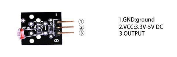
LDR (Light Dependent Resistor). Dark resistance >20M Ohm, light <80 Ohm. The two outer pins connect to the LDR. A fixed 10 K ohm resistor connected between the middle pin and the ‘S’ pin is included on the module. This simplifies the building of a measurement bridge circuit.
¶ Component Introduction
Light dependentresistor:
The photocell used is of a type called a light dependent resistor, sometimes called an LDR. As the name suggests, these components act just like a resistor, except that the resistance changes in response to how much light is falling on them.
This one has a resistance of about 50 kΩ in near darkness and 500Ω in brightlight. To convert this varyingvalue ofresistance into somethingwe ca measureon anArduino's analoginput, it need to be converted into avoltage.
The simplest way to do that is to combine it with a fixedresistor.
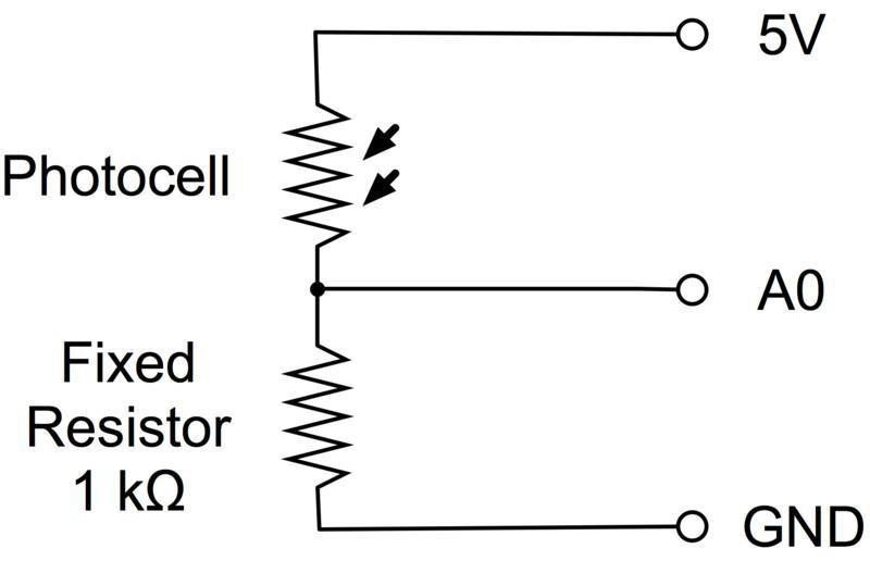
The resistor and photocell together behave rather like a pot. When the light is very bright, then the resistance of the photocell is very low compared with the fixed value resistor, and so it is as if the pot were turned tomaximum.
When the photocell isin dull light the resistance becomes greater than the fixed 1kΩresistor and it is as if the pot were being turned towards GND.
Load up the sketch given in the next section and try covering the photocell with yourfinger, and holding it near a lightsource.
¶ Connection Schematic
¶ Wiring diagram
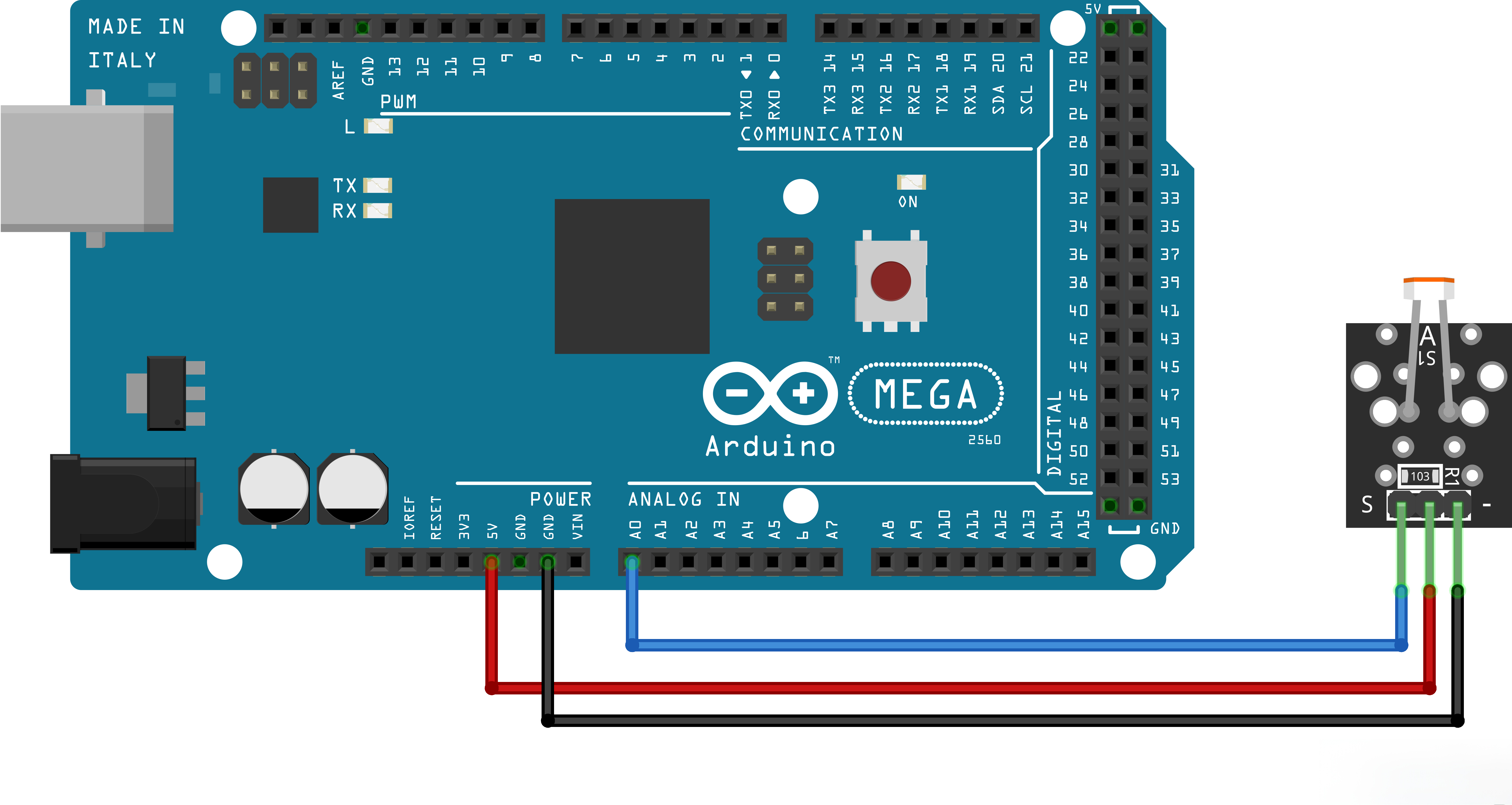
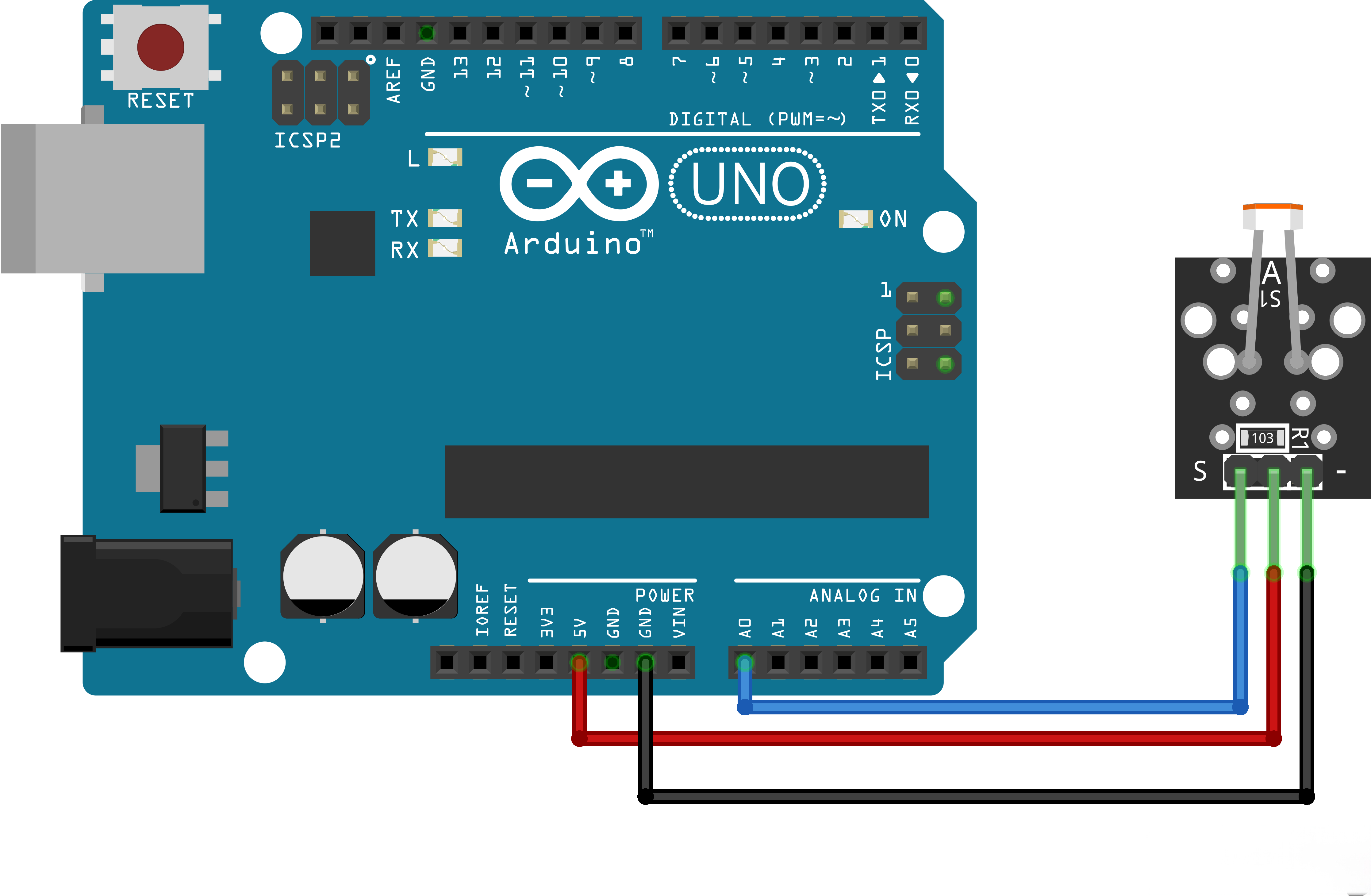
¶ Code
You can click the blue text link to download the program file to your local device, and double-click the file to open it after the download is complete. Please note: Before opening the file, ensure that you have installed the Arduino IDE development environment and completed the installation of relevant components such as the board support package and driver corresponding to the board.
¶ Code Explanation
int sensorPin = 34; // select the input pin for the potentiometer
int ledPin = 5; // select the pin for the LED
int sensorValue = 0; // variable to store the value coming from the sensor
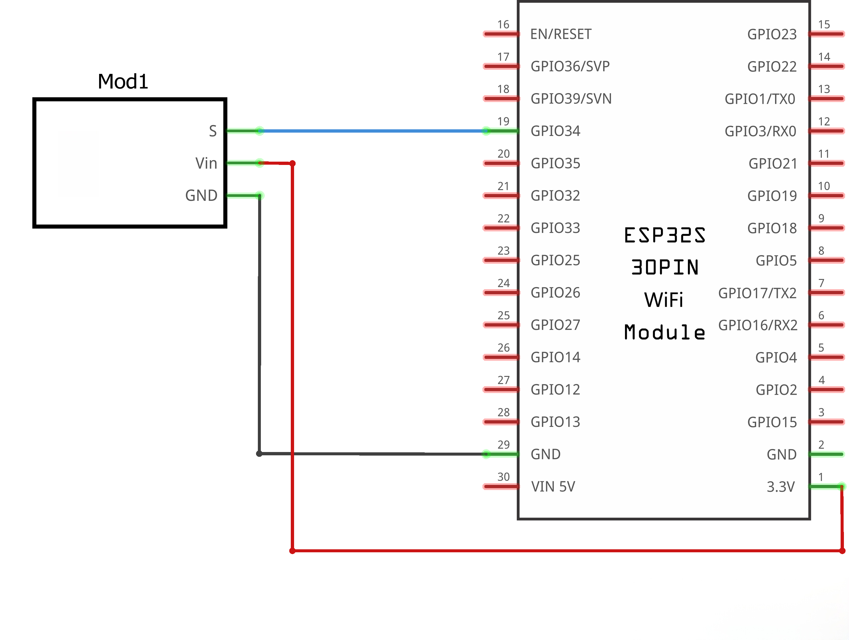
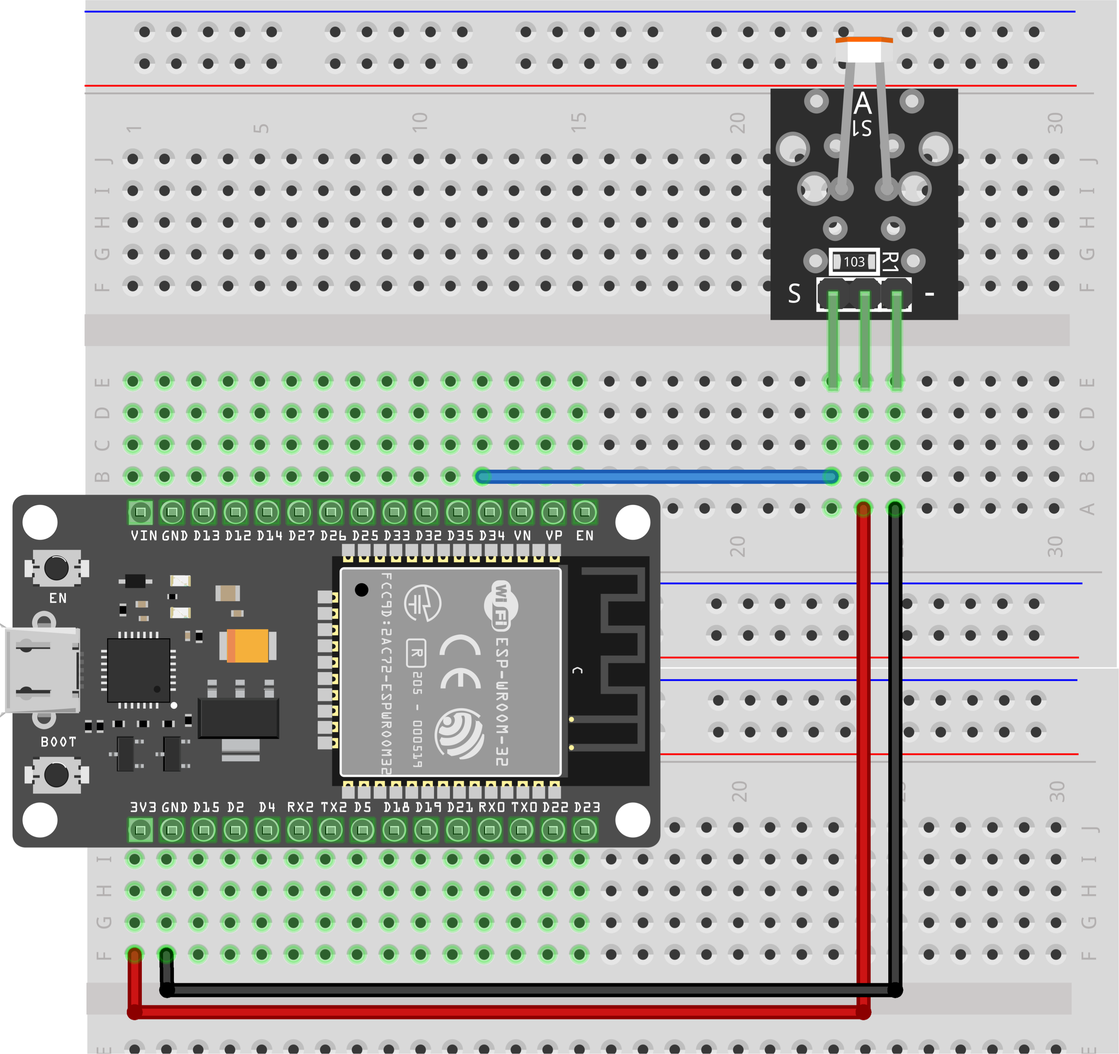
The sensor pin, LED pin and a variable are defined in this part. Note that when using ESP32, pins numbered 32 to 34 are recommended for the sensor. If you adopt other types of main control boards, make sure the connected pins support PWM function.
void loop(){
sensorValue = analogRead(sensorPin);
digitalWrite(ledPin, HIGH);
delay(sensorValue);
digitalWrite(ledPin, LOW);
delay(sensorValue);Serial.println(sensorValue,DEC);
}
sensorValue = analogRead(sensorPin);
The value collected by the sensor is read and assigned to the variable sensorValue. Normally, you can view the output value ranging roughly from 300 to 500 after opening the serial monitor. The brighter the ambient light, the smaller the obtained value; conversely, the darker the light, the larger the value.
delay(sensorValue);
The delay time is determined by the value collected from the sensor, which brings the following LED flashing effect: the darker the ambient light, the slower the indicator light flashes; the brighter the light, the faster the light flashes.