¶ Laser Module
¶ Overview
In this experiment, we will learn how to use laser module.
¶ Laser emitter
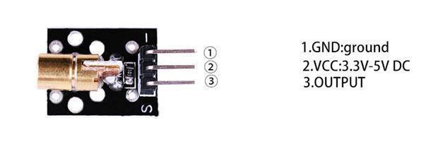
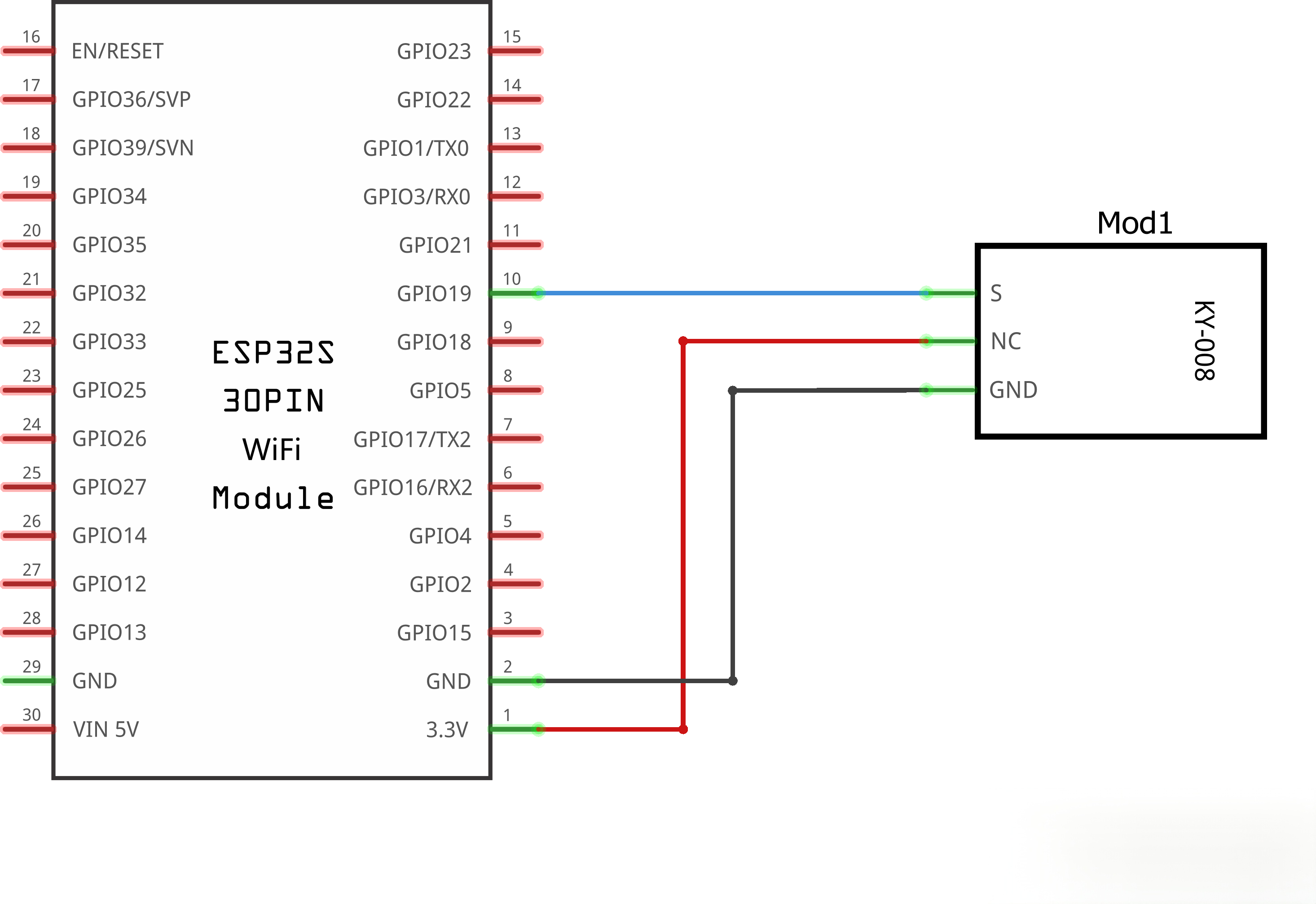
Connect the first ("-") pin on the ir module to GND pin on the board, and the second pin to the 5V pin on board, last but not least, the third ("S") pin to the digital port 9.
Transmission Wavelength: 650 nm
¶ Component Introduction
Lasersensor:
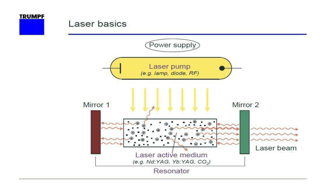
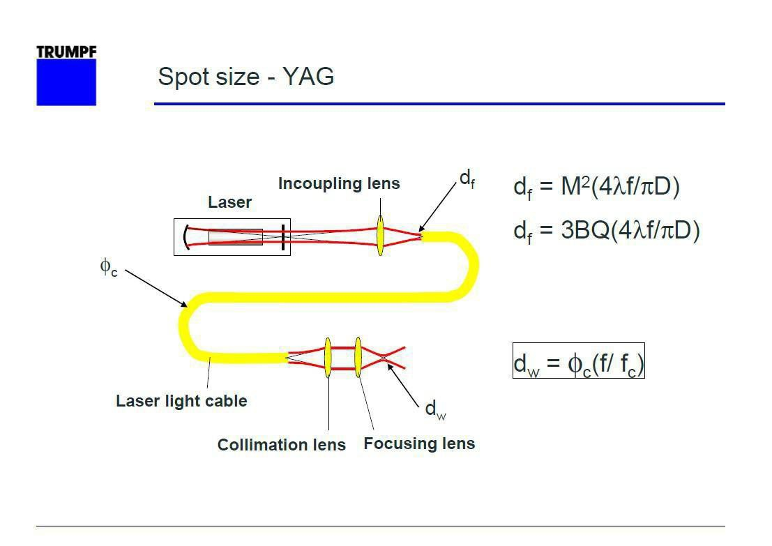
The laser module can be controlled by both digital signals and analog signals. If you only need to turn it on or off, you can treat it as a regular LED.
It lights up when a high level is given and turns off with a low level, but you cannot adjust its brightness in this way.
You can adjust the brightness by using analog signals. A series of values ranging from 0 to 255 can be input, with each value corresponding to a specific brightness. Here, 0 stands for the darkest state and 255 for the brightest.
¶ Connection Schematic
¶ Wiring Diagram
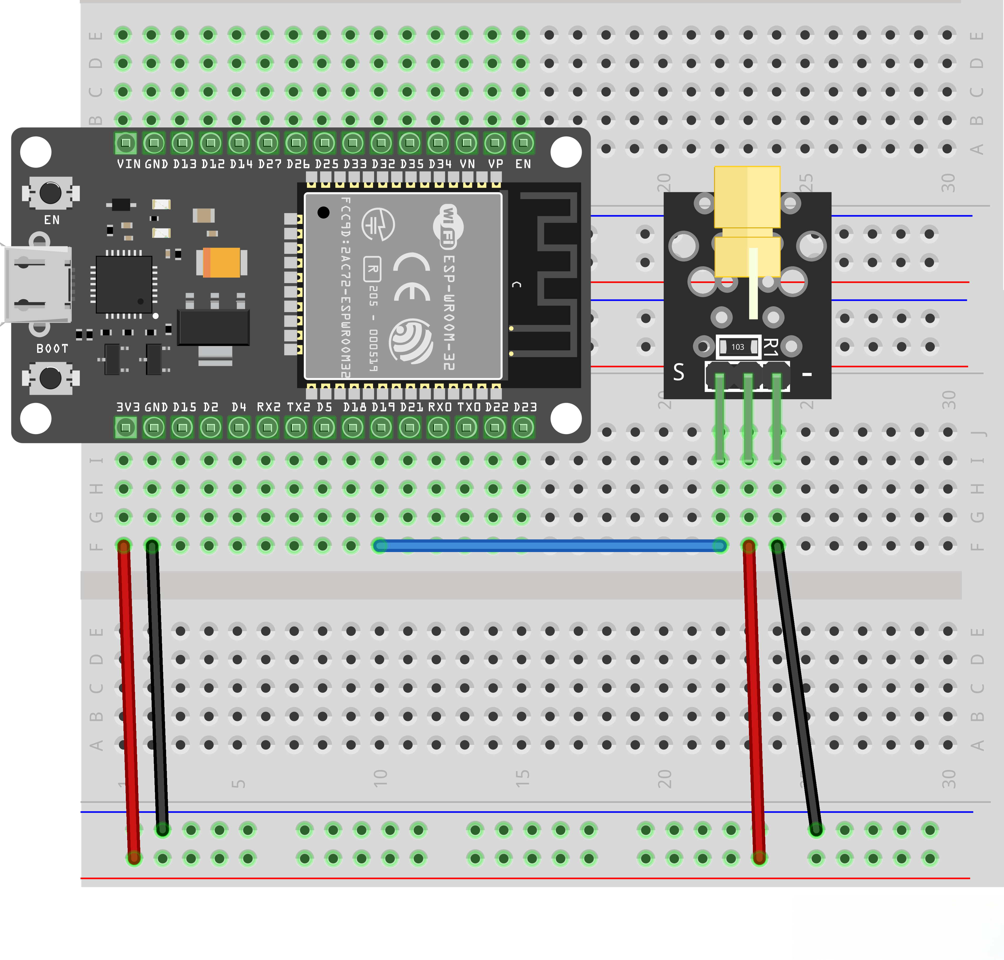
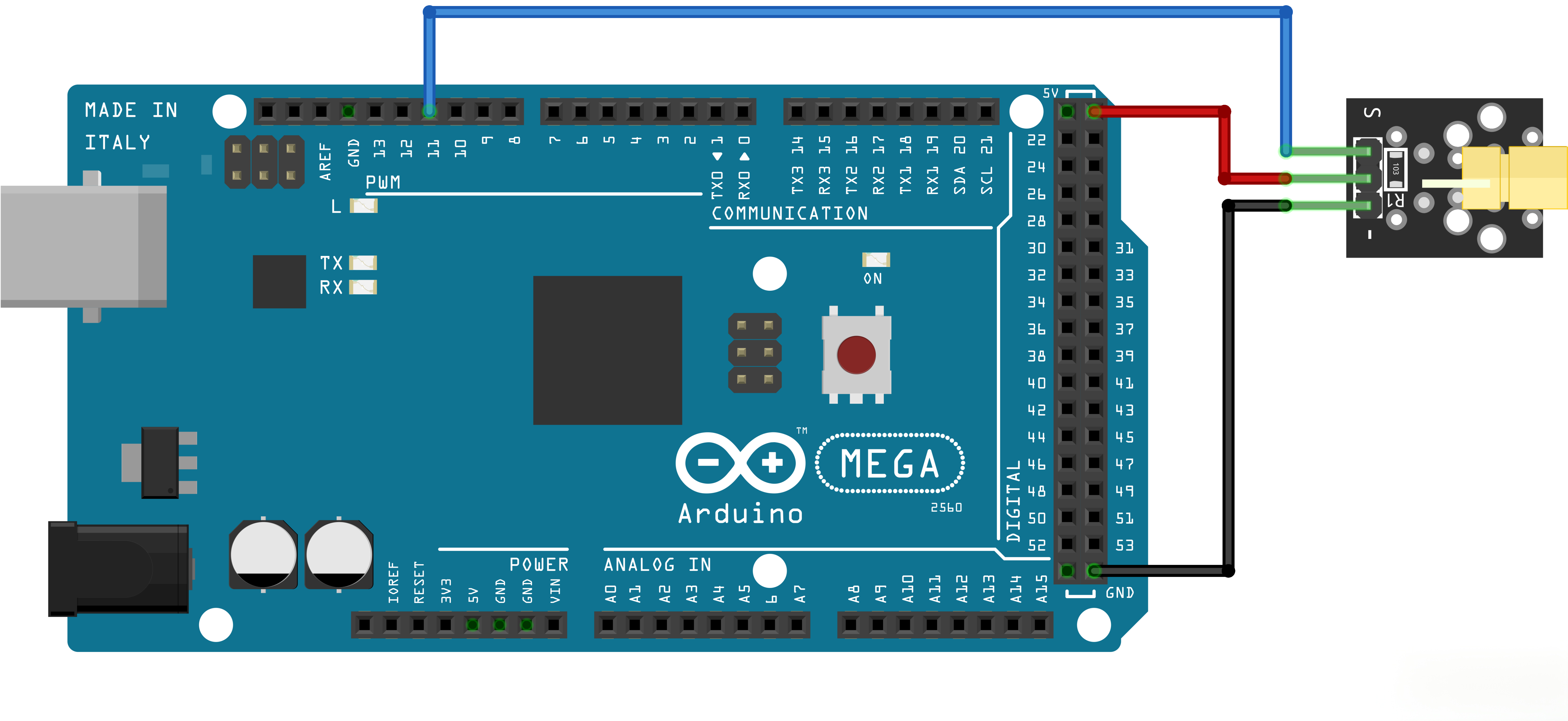
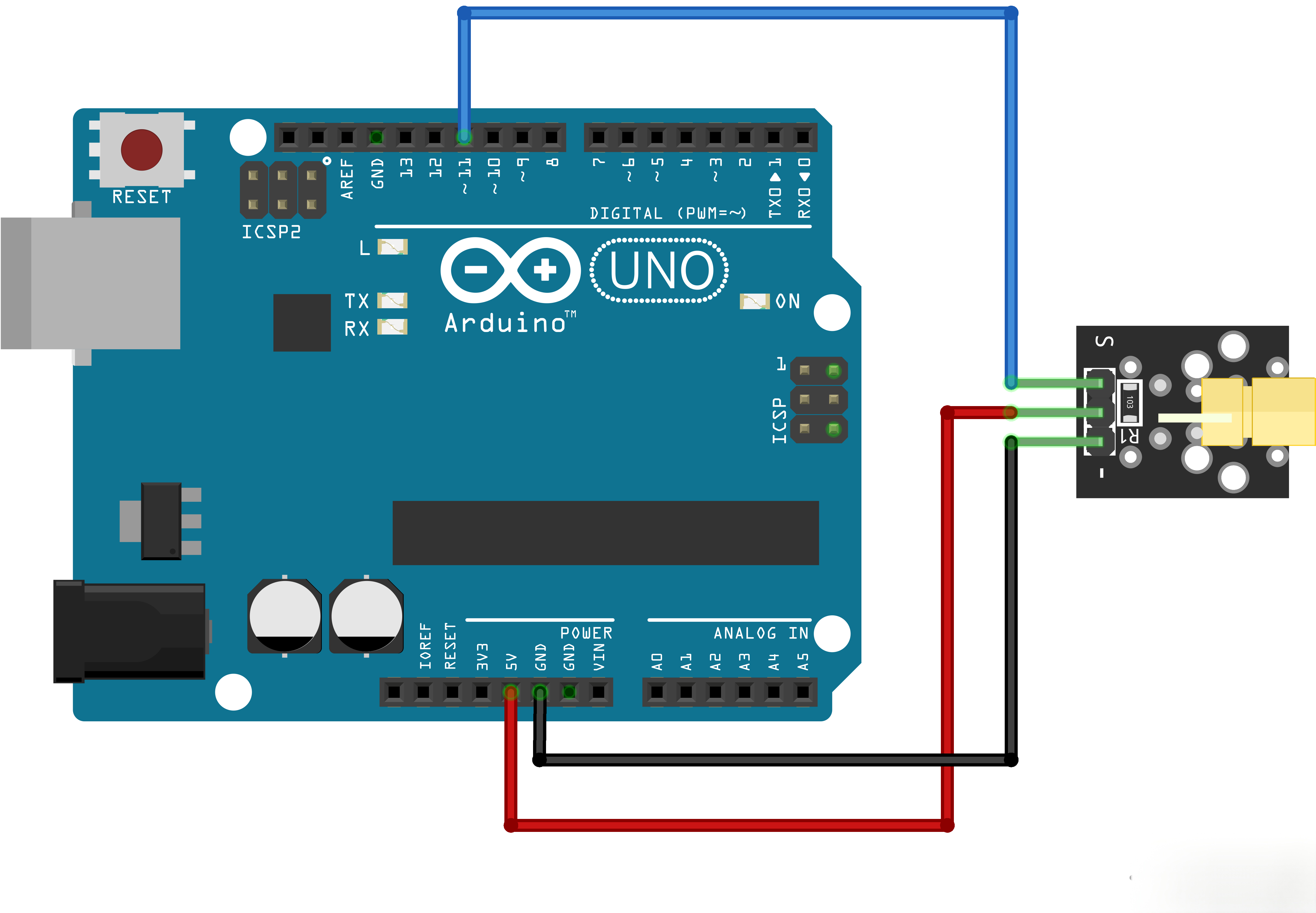
¶ Code
You can click the blue text link to download the program file to your local device, and double-click the file to open it after the download is complete. Please note: Before opening the file, ensure that you have installed the Arduino IDE development environment and completed the installation of relevant components such as the board support package and driver corresponding to the board.
int pos = 0; //Set a variable for adjusting brightness
pinMode(19,OUTPUT);
These are the available pins for ESP32. If you use an UNO series board, please select PWM pins marked with the tilde symbol ~ for wiring.
//Digital input only lights up
digitalWrite(19, 1);
delay(3000);
digitalWrite(19, 0);
delay(3000);
If you only need to turn the laser module on or off, you can use digital signal control, and the module will work at full brightness once turned on.
//Analog input adjusts brightness
// for (pos = 0; pos <= 255; pos += 1)
// {// analogWrite(19,pos);
// delay(25);
// }
// for (pos = 255; pos >= 0; pos -= 1)
// {
// analogWrite(19,pos);
// delay(25);
// }
If you want to adjust the power slowly or set a fixed power level, you can use analog output to customize the corresponding brightness and operating power.