¶ ESP32 IoT WiFi Control System
💡 A Note for Newcomers: Don't panic! This tutorial is written specifically for first-time ESP32 users. Every step is explained in detail — just follow along and you'll succeed. If you run into trouble, jump straight to the Troubleshooting section near the end — almost every issue has an answer there.
¶ 📋 What You'll Build
By completing this project, you'll have a smart ESP32 device that you can control from your phone:
- 📱 Connect your phone to the WiFi hotspot created by the ESP32 and control it via a web page
- ⏰ View accurate network time and set alarms (buzzer will ring)
- 🌡️ Real-time temperature and humidity display (both on OLED screen and your phone)
- 💡 Remotely turn the onboard LED on and off
- ⚙️ Remotely control a motor/relay (can be extended to fans, lights, etc.)
Simple Analogy: Think of it like using your phone to control your home AC — your phone is the remote, the ESP32 is the AC, and WiFi is the "telephone line" connecting them.
¶ 🧰 Step 1: Prepare Your Tools (Hardware + Software)
¶ Hardware Checklist
Gather the following items (check them off as you go):
| # | Component Name | Quantity | Purpose | ✅ Done |
|---|---|---|---|---|
| 1 | ESP32 Development Board | 1 pc | Main controller | ☐ |
| 2 | DHT11 Temperature & Humidity Sensor | 1 pc | Measure temp & humidity | ☐ |
| 3 | 0.96" OLED Display (128×64, I2C) | 1 pc | Show time, temp & humidity | ☐ |
| 4 | Passive Buzzer (3.3V-5V, PWM driven) | 1 pc | Alarm ringing (requires PWM square wave) | ☐ |
| 5 | DC Motor | 1 set | Remote motor control | ☐ |
| 6 | Push Button (tactile switch) | 1 pc | Manually stop alarm when ringing | ☐ |
| 7 | Breadboard | 1 pc | For easy wiring | ☐ |
| 8 | Jumper Wires (M-M, M-F) | Several | Connect everything together | ☐ |
| 9 | Micro USB / Type-C Data Cable (NOT charge-only!) | 1 pc | Connect PC to flash code | ☐ |
¶ 🔌 Step 2: Hardware Wiring
⚠️ CRITICAL SAFETY WARNING: Always DISCONNECT the ESP32 from USB power before wiring! Check your connections 3 times before applying power. Wrong wiring can damage your components!
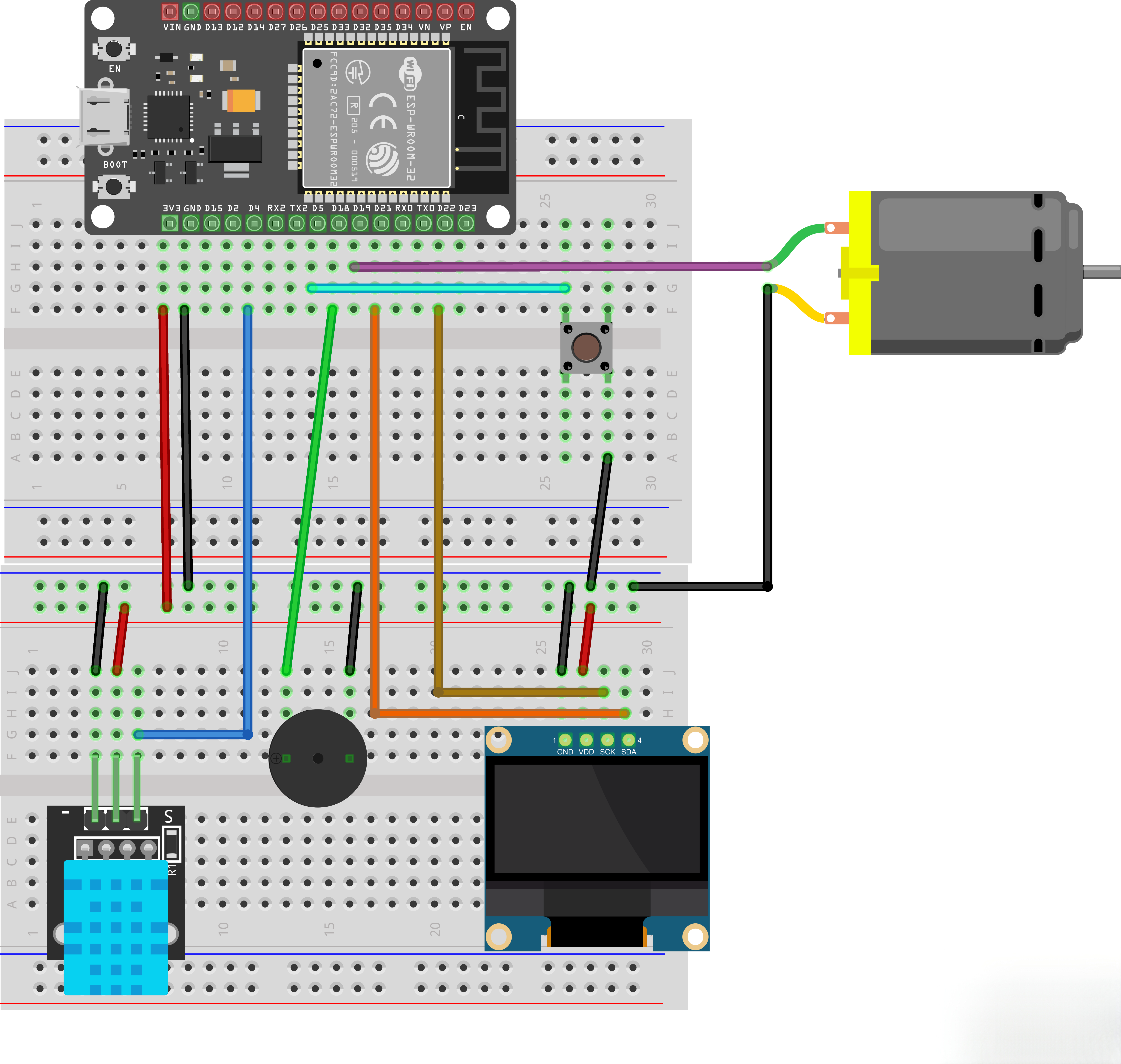
¶ Wiring Table (FOLLOW THIS EXACTLY!)
| ESP32 Pin | Connects To | Notes |
|---|---|---|
| GPIO4 | DHT11 DATA / OUT | Temperature/humidity data pin |
| GPIO21 | OLED SDA | I2C Data Line |
| GPIO22 | OLED SCL | I2C Clock Line |
| GPIO18 | Passive Buzzer Signal Pin (IN / SIG) | PWM-driven buzzer ringing |
| GPIO19 | Motor Driver Module IN1 / Signal Input | Control motor on/off |
| GPIO5 | Push Button (other terminal) | Manually stop alarm when ringing |
| GPIO2 (Built-in) | (Already on the board, no wiring needed) | Onboard LED |
¶ Connection Schematic

¶ Wiring diagram
¶ 💻 Step 3: Software Setup & Code Flashing (6 Simple Steps)
¶ Step 3.1: Add ESP32 Board Support to Arduino IDE
¶ Step 3.2: Install Required Libraries
Open the libraries folder in the project folder, then load it following the library loading process.
¶ Step 3.3: Open the Project Code
- Copy the entire project folder (
Internet_of_Things_WIFI_Control_System_ESP32) to a location you can easily find (like your Desktop) - Double-click the
Internet_of_Things_WIFI_Control_System_ESP32.inofile inside that folder — it will automatically open in Arduino IDE - 💡 Notice the multiple tabs at the top of the IDE:
.ino,NTPTime.cpp,OLEDDisplay.cpp, etc. — this is the "multi-file modular" structure. Each file handles one specific job (we'll explain this in detail later).
¶ Step 3.4: Modify WiFi Configuration (THE MOST IMPORTANT STEP!)
⚠️ If you skip this step, WiFi connection WILL fail later!
-
In the tabs at the top of the IDE window, click to switch to the WebServer.cpp file
-
Find this section of code (around line 10):
// STA mode configuration: Connects to your router to get NTP time const char* sta_ssid = "YourWiFiName"; // ⚠️ Change to YOUR WiFi name! const char* sta_password = "YourWiFiPassword"; // ⚠️ Change to YOUR WiFi password! -
Replace the text inside the double quotes with your own home WiFi credentials:
sta_ssid: Change to your WiFi name (SSID)sta_password: Change to your WiFi password
Example:
const char* sta_ssid = "MyHomeNetwork"; const char* sta_password = "mypassword123"; -
(Optional) If you want a custom hotspot name and password, modify these too:
const char* ap_ssid       = "ESP32_AP";     // Name shown in phone WiFi list
const char* ap_password   = "12345678";      // Hotspot password — at least 8 chars
¶ Step 3.5: Select Board & Flash the Code
¶ Step 3.6: Observe the Boot Process (Serial Monitor)
After successful flashing, let's use the Serial Monitor to see what the ESP32 is doing:
- Click the 🔌 Serial Monitor button in the top-right of the IDE (looks like a plug icon), or press
Ctrl+Shift+M - In the bottom-right corner of the Serial Monitor window, set the baud rate to 115200 (EXTREMELY IMPORTANT! Wrong baud rate = garbage text)
- Press the EN Button (Reset button) on your ESP32 board to restart it
- Watch the output in the Serial Monitor — compare it against the Expected Output section below
¶ ✅ Step 4: Check if Everything Works
¶ 4.1 Expected Serial Monitor Output
¶ 🎉 Case 1: WiFi + NTP Both Connected Successfully (Normal Operation)
=== Getting NTP time at startup ===
Connecting to WiFi: MyHomeNetwork
.....
✅ WiFi connected successfully!
NTP sync attempt 1/30: ✅ Success!
Current time: 15:30:45

📶 Starting AP hotspot: ESP32_AP
AP IP address: 192.168.4.1
Time: 15:30:46
T = 25.5 deg. C, H = 60.0%
Time: 15:30:47
...
- See
✅ WiFi connected successfully!→ WiFi connected ✔ - See
NTP sync attempt 1/30: ✅ Success!→ Time synchronized ✔ - See
AP IP address: 192.168.4.1→ Hotspot created successfully ✔ - Time prints once per second → System running normally ✔
¶ 😅 Case 2: WiFi Connection Failed (Code still runs!)
=== Getting NTP time at startup ===
Connecting to WiFi: WrongSSID
........................................
❌ WiFi connection failed, unable to sync NTP time

📶 Starting AP hotspot: ESP32_AP
AP IP address: 192.168.4.1
Time: 00:00:01
Time: 00:00:02
...
- In this case, the internal clock will start from
00:00:00(like a digital watch that hasn't been set) - However, the hotspot and remote control functions STILL WORK — only the time/alarm accuracy will be off
¶ 4.2 What You Should See on the OLED Screen
After successful OLED initialization, the screen should display:
┌──────────────────────────────┐
│ ALARM 08:30                   ← Shows here ONLY if alarm is set
│ 08:30  45                    ← Large Hours:Minutes + Seconds
│ T:25.5C          H:60.0%     ← Temperature and Humidity
└──────────────────────────────┘
When sensor fails: If the DHT11 reading fails (wiring issue or sensor fault), the bottom row will show ERR instead of values, for example:
┌──────────────────────────────┐
│ 08:30  45
│ T:ERRC           H:ERR%     ← Sensor reading abnormal
└──────────────────────────────┘
If the screen is blank, go to Troubleshooting Q3 / Q4 below.
¶ 4.3 Connect Your Phone and Take Control
- Open your phone's WiFi Settings
- Find the WiFi network named
ESP32_AP(or your custom hotspot name) and tap to connect - Enter the password:
12345678(or your custom password) - 💡 After connecting, your phone may warn "This hotspot has no internet access" — this is NORMAL! The ESP32 itself can't go online. If your phone asks "Stay connected?", always choose Stay Connected / Don't Switch.
- Open any web browser on your phone (Chrome, Safari, the default browser — all work fine)
- Type
192.168.4.1in the address bar and press Enter / Go - 🎉 You should see the control page! Try clicking the buttons:
- LED ON / LED OFF: The onboard LED on ESP32 lights up / turns off
- Motor ON / Motor OFF: Motor starts / stops spinning
- Set Alarm: Enter hour and minute, then click "Set Alarm"
- Turn Off Alarm: If alarm is ringing, this stops it immediately
- Physical Button Stop: Besides the web button, you can also press the physical button connected to GPIO5 to stop the alarm directly
¶ 🤔 Step 5: Troubleshooting Guide
¶ Q1: Serial Monitor shows garbage text or is completely blank?
A: This is the #1 beginner mistake — almost 100% of the time it's the wrong baud rate.
- Check the baud rate dropdown in the bottom-right of the Serial Monitor. It MUST be 115200.
- After changing the baud rate, press the EN (Reset) button on the ESP32 to restart it.
¶ Q2: WiFi never connects. Prints many dots (..........) then fails?
A: Check each of these systematically, in order:
- 🔴 Verify WiFi Name & Password:
- Open
WebServer.cppand double-check thatsta_ssidandsta_passwordare correct - They are case sensitive!
- Are there any extra spaces accidentally added?
- Open
- 🔴 Confirm it's 2.4GHz WiFi:
- ESP32 does NOT support 5GHz!
- Log into your router admin panel and confirm the 2.4GHz band is enabled
- Some routers use the same name for both 2.4GHz and 5GHz — try giving the 2.4GHz network a unique SSID
- 🔴 Check Router MAC Address Filtering:
- Does your router have "MAC Address Filtering" or "Access Control" enabled?
- If yes, either temporarily disable it or add the ESP32's MAC address to the whitelist
- 🔴 Special Characters in Password:
- If your password contains spaces, non-Latin characters, or unusual symbols, test with a simple alphanumeric password first
- 🔴 Signal Strength:
- Is the ESP32 too far from the router? Move it closer and try again.
¶ Q3: OLED shows nothing and Serial says "OLED initialization failed"?
A: OLED failed to initialize. Check each item:
- Wiring Issues:
- OLED SDA → ESP32 GPIO21
- OLED SCL → ESP32 GPIO22
- OLED VCC → 3.3V (Some OLEDs tolerate 5V — try that too)
- OLED GND → ESP32 GND (MUST be common ground!)
- Wrong I2C Address:
- Most OLED modules use address
0x3C, but a few use0x3D - Open
OLEDDisplay.cpp, find theoledInit()function - Try changing
0x3Cto0x3Din thedisplay.begin(...)call
- Most OLED modules use address
- Insufficient Power:
- Some OLED modules are voltage-sensitive. If 3.3V doesn't work, try 5V.
- Defective Module:
- Tried everything above and still dead? The OLED module itself might be faulty. Try another one.
¶ Q4: OLED doesn't report "initialization failed" but the screen is blank or very dim?
A: This is almost always a contrast/brightness issue. In OLEDDisplay.cpp, in the oledInit() function, add these two lines AFTER display.begin(...):
display.ssd1306_command(SSD1306_SETCONTRAST);
display.ssd1306_command(0xCF);   // 0x00 = dimmest, 0xFF = brightest. Adjust to taste.
¶ Q5: DHT11 readings are always 0.0?
A: Check each item:
- Wiring Issues:
- DHT11 DATA → ESP32 GPIO4
- DHT11 VCC → 3.3V (ESP32 is 3.3V logic, do NOT use 5V)
- DHT11 GND → ESP32 GND (MUST be common ground!)
- 4.7kΩ Pull-Up Resistor:
- 🔴 A 4.7kΩ pull-up resistor MUST be connected between DHT11 DATA and VCC! This is required by the DHT11's open-drain output
- Some DHT11 modules have this resistor built-in (check the back of the module for an "S" mark or resistor)
- Without the pull-up resistor, the DATA pin level is undefined and readings will fail
- Pin Order:
- 🔴 DHT11 modules come in TWO different pinouts! Always check the silk screen on the BACK of your module:
- Variant A: VCC → DATA → GND (left to right)
- Variant B: DATA → VCC → GND (left to right)
- Wrong pin order = either no readings OR permanent sensor damage!
- 🔴 DHT11 modules come in TWO different pinouts! Always check the silk screen on the BACK of your module:
- Warm-Up Time:
- DHT11 needs 1~2 seconds to stabilize after power-on. The code already includes a 2-second wait
- DHT11 minimum sampling interval is 2 seconds — do not read too frequently
- Dead Sensor:
- Try a different DHT11 module
¶ Q6: Phone can't find the "ESP32_AP" hotspot?
A:
- Was the code actually flashed successfully?
- Check that the IDE showed "Done uploading"
- Open the Serial Monitor at 115200 baud, press EN to reset, and look for output
- Press the EN Button:
- After flashing, press the EN (Reset) button once to ensure the code is running
- Password Length Check:
- AP password must be at least 8 characters. Fewer than 8 = hotspot creation failure.
¶ Q7: Phone connects to hotspot but browser can't open 192.168.4.1?
A:
- Did your phone auto-switch WiFi?
- Many Android phones detect that the hotspot has "no internet" and automatically switch back to a WiFi network that does have internet
- Fix: In phone WiFi settings, DISABLE "Smart Switch", "WiFi+", "Auto-switch", or similar options
- Or explicitly select the option to "Stay Connected" / "Don't Switch"
- Browser using Proxy / VPN?
- Turn off any proxy, VPN, or ad-blocking services on your phone
- Try Incognito / Private Browsing Mode:
- Open an Incognito / Private Browsing window in the browser and try entering
192.168.4.1again
- Open an Incognito / Private Browsing window in the browser and try entering
- Manually Set Static IP on Phone:
- In phone WiFi settings, long-press
ESP32_AP→ Modify Network → Static IP settings:- IP:
192.168.4.2 - Gateway:
192.168.4.1 - Subnet Mask:
255.255.255.0
- IP:
- In phone WiFi settings, long-press
¶ Q8: Web page opens but clicking buttons does nothing?
A:
- Check for output in Serial Monitor:
- When you click a button, the Serial Monitor should print something like
Request: GET /H HTTP/1.1 - If NO output → Browser request never reached the ESP32 (go back and fix Q7)
- If OUTPUT shows up but LED doesn't light → Possible code logic issue
- When you click a button, the Serial Monitor should print something like
- Refresh the page and try again:
- Restart the ESP32 (press EN button):
¶ Q9: Alarm doesn't ring at the set time?
A:
- Wiring Issues:
- Buzzer Signal Pin → ESP32 GPIO18
- Buzzer VCC → 3.3V or 5V
- Buzzer GND → ESP32 GND (MUST be common ground!)
- Buzzer Type:
- 🔴 This project uses a PASSIVE buzzer (PWM driven):
- Passive Buzzer: Requires a PWM square wave signal (code uses
tone()to output 1000Hz square wave) — DC voltage alone won't make it sound → ✅ This project is designed for these - Active Buzzer: Rings immediately when you apply DC voltage → ❌ Won't work with this code as-is
- Passive Buzzer: Requires a PWM square wave signal (code uses
- How to test: Connect buzzer VCC to 3.3V and GND directly to GND — if it rings, it's active (won't work with this code); if silent, it's passive (correct for this project)
- 🔴 This project uses a PASSIVE buzzer (PWM driven):
- Is the Clock Correct?
- Compare the time shown on the OLED against the actual current time
- If time starts from 00:00, the NTP sync failed (go fix Q2 first)
- Was the Alarm Actually Set?
- After setting the alarm on the web page, does
ALARM XX:XXappear at the top of the OLED? - Did the Serial Monitor print
⏰ Alarm set: XX:XX?
- After setting the alarm on the web page, does
- Alarm triggers at the 0th SECOND of the target minute:
- Example: If you set alarm 08:30, it will trigger ONLY at exactly 08:30:00 (the very first second of that minute) — it will NOT ring continuously through the entire 08:30 minute
- For quick testing, set the alarm to "current time + 1 minute"
- Use Physical Button to Stop Alarm:
- Besides the "Turn Off Alarm" web button, you can also press the physical button on GPIO5 to stop the alarm ringing directly
¶ Q10: Motor doesn't spin?
A:
- Wiring Issues:
- Motor Driver Module IN1 → ESP32 GPIO19
- Motor Driver Module GND → ESP32 GND (MUST be common ground!)
- Motor's two wires → Driver output terminals (OUT1 / OUT2)
- Insufficient starting current?
- 🔴 The ESP32 can only drive the motor temporarily! Be sure to use a driver module such as L293D for long-term operation. If the motor fails to rotate when pressing the button, gently turn the output shaft with your finger to assist startup. Please turn off the motor promptly once testing is completed.
- Check Serial Monitor Output:
- When you click the button, the Serial Monitor should print
Motor state updated: ON - If output appears but motor doesn't move → Problem is in motor wiring / driver / power supply
- If NO output appears → Go back and fix Q8 first
- When you click the button, the Serial Monitor should print
¶ 🔍 Quick Troubleshooting Lookup Table (Fast Diagnosis)
| Symptom | Most Likely Cause | Fastest Fix |
|---|---|---|
| Serial garbage / blank | Wrong baud rate | Set to 115200, press EN to reset |
| WiFi won't connect (many dots) | Wrong password / 5GHz WiFi | Verify credentials, use 2.4GHz |
| OLED blank + error message | Wrong wiring / wrong I2C address | Check I2C wiring, try address 0x3D |
| OLED blank + NO error | Contrast too low | Add contrast adjustment code |
| OLED shows T:ERR / H:ERR | DHT11 wiring issue / sensor fault | Check GPIO4 wiring and 4.7kΩ pull-up resistor |
| DHT11 always 0.0 | Wrong wiring / reversed pin order | Check GPIO4, verify pinout on silk screen |
| Can't find hotspot | Code not flashed properly | Re-flash code, press EN to reset |
| Can't open web page | Phone auto-switched WiFi | Disable auto-switch, try incognito mode |
| Buttons unresponsive | Browser cache | Refresh page / restart ESP32 |
| Alarm silent | Wrong wiring / wrong buzzer type | Check GPIO18, use passive buzzer (PWM driven) |
| Motor won't move | No driver / no external power | Add motor driver, connect motor power supply |
| Physical button can't stop alarm | Button wiring / no pull-up | Check GPIO5 wiring, button's other terminal to GND |
¶ 📚 Step 6: Background Knowledge (Read This After Getting it Working!)
💡 Congratulations if you've already gotten the project working! This section is for those who want to understand the "why" behind the code. First-timers can safely skip this and just enjoy the feeling of success.
¶ 6.1 What is an IoT Control System?
IoT (Internet of Things) is all about connecting devices together through a network so they can communicate and be controlled remotely.
This project is a classic three-layer IoT application:
- Perception Layer (Eyes & Ears): DHT11 sensor feels the environment's temperature and humidity
- Transport Layer (Nerves): WiFi sends data out and receives commands in
- Application Layer (Brain): You, using a web page on your phone, view data and send control commands
¶ 6.2 Project Architecture: Why Multi-File?
The project code is split into 9 files, each responsible for one specific thing. This is called multi-file modular programming.
| File Name | What It Does | Real-World Analogy |
|---|---|---|
Internet_of_Things_WIFI_Control_System_ESP32.ino |
Main program, the boss | Company CEO |
NTPTime.h / .cpp |
Connects WiFi, fetches network time | Admin Dept — keeps the clock accurate |
DHTSensor.h / .cpp |
Reads DHT11 temp & humidity | Environmental monitor |
OLEDDisplay.h / .cpp |
Controls OLED screen display | Receptionist — shows info to visitors |
WebServer.h / .cpp |
Creates hotspot, handles web requests | Customer Service Dept |
Module Relationship Diagram:
Main Program (.ino) —— calls → NTPTime Module (get time)
                ↘→ DHTSensor Module (read temp & humidity)
                ↘→ OLEDDisplay Module (display info)
                ↘→ WebServer Module (create hotspot + web page)
Why Use Modular Programming?
| Advantage | Explanation |
|---|---|
| Easy to Debug | If temp/humidity is wrong, just look in DHTSensor.cpp — no need to hunt through 1000 lines |
| Easy to Reuse | Need OLED in your next project? Just copy OLEDDisplay.h/.cpp straight over! |
| Clear Logic | Each file does one thing — fewer chances of bugs |
¶ 6.3 STA Mode vs AP Mode
Boot-Up Sequence Used in This Project:
- First use STA Mode to connect to your home router → Fetch accurate time from an NTP server
- After obtaining the time, disconnect from STA mode
- Switch to AP Mode to create a hotspot → Your phone can connect and take control
Why switch modes? While ESP32 technically supports simultaneous STA+AP (hybrid mode), in practice it causes many resource conflicts and poor stability. Sequential switching ("STA for time → disconnect → start AP") gives far higher reliability.
¶ 6.4 Why Use millis() Instead of delay()?
This is a very important concept in embedded programming — non-blocking programming.
❌ The Problem with delay(1000): It "freezes" the entire program for 1 full second. During that frozen time, it can't ring alarms, can't handle web requests, can't read buttons.
✅ The Beauty of millis(): millis() returns "how many milliseconds have elapsed since boot". We use this to check if "enough time has passed" — if not, we move on and do other things.
// Correct approach: Non-blocking
if (millis() - lastTime >= 1000) {
  lastTime = millis();
  // 1 second is up — execute the timed task
}
// Code below here keeps running every single loop — never gets stuck!
📌 About the
statickeyword: Astaticvariable declared inside a function is NOT destroyed when the function exits — the next time the function is called, it still remembers its old value. Think of it as "memory" inside a function — perfect for remembering when we last did something.
📌
tone()/noTone()— PWM Drive for Passive Buzzer: This project uses a passive buzzer which requires a PWM square wave to produce sound.tone(pin, 1000)generates a 1000Hz square wave on the pin, andnoTone(pin)stops it. Compared to manually flipping pin levels withmillis(),tone()is implemented by hardware timers and doesn't consume any CPU time — much more efficient.
📌 Button Detection — Falling Edge Trigger: The physical button uses "falling edge detection" — it only triggers once at the exact moment the button transitions from released (HIGH) to pressed (LOW), rather than continuously triggering while held down. This is implemented using a
staticvariable to remember the previous button state.
¶ 🔍 Step 7: Detailed Code Walkthrough (Advanced Learning)
¶ 7.1 Main Program File: .ino
¶ 7.1.1 Headers and Pin Definitions
#include <WiFi.h>            // ESP32 WiFi library (NOT WiFiS3.h!)
#include <Wire.h>            // I2C communication (for OLED)
#include "OLEDDisplay.h"     // OLED display module
#include "WebServer.h"       // Web server module
#include "NTPTime.h"         // NTP time module
#include "DHTSensor.h"       // Temp/humidity sensor module

// ==================== Buzzer (passive, PWM driven) ====================
#define BUZZER_PIN 18       // Buzzer → GPIO18
#define BUZZER_FREQ 1000    // 1000Hz PWM frequency (passive buzzer needs square wave)

// ==================== Buzzer Stop Button ====================
#define BUZZER_BTN_PIN 5    // Button → GPIO5

// ==================== Motor Control ====================
#define MOTOR_PIN 19        // Motor → GPIO19

// ==================== LED ====================
#define LED_PIN 2           // Onboard LED → GPIO2

bool motorState = false;  // Motor on/off state variable

// Global variables
unsigned long currentUnixTime = 0;  // Current timestamp (seconds)
unsigned long lastUpdateTime  = 0;  // Last update time (milliseconds)

// Alarm variables
int alarmHour   = 0;
int alarmMin    = 0;
bool alarmOn    = false;   // Whether alarm is enabled
bool alarmRing  = false;   // Whether alarm is currently ringing

// Temperature & Humidity variables
float temperature = 0.0;
float humidity    = 0.0;
¶ 7.1.2 setup(): Initialization Function (Runs ONCE at boot)
void setup() {
  Serial.begin(115200);      // Initialize serial at 115200 baud
  delay(1000);

  pinMode(LED_PIN, OUTPUT);     // Set LED pin as output
  pinMode(MOTOR_PIN, OUTPUT);   // Set motor pin as output
  digitalWrite(LED_PIN, LOW);   // Initial state: LED OFF
  digitalWrite(MOTOR_PIN, LOW); // Initial state: motor OFF

  // Buzzer stop button (active low with internal pull-up)
  pinMode(BUZZER_BTN_PIN, INPUT_PULLUP);

  // Wait for DHT11 sensor to stabilize
  Serial.print("[DHT] Sensor type: DHT11, Pin: GPIO");
  Serial.println(DHT_SENSOR_PIN);
  Serial.println("[DHT] Waiting for sensor stabilization...");
  delay(2000);

  Wire.begin(21, 22);          // I2C init: SDA=GPIO21, SCL=GPIO22
  oledInit();                  // Initialize OLED display

  // ===== Boot-up Sequence =====
  getNetTime(currentUnixTime);   // Step 1: Connect WiFi, get NTP time
  startAPMode();                  // Step 2: Switch to AP mode, create hotspot
  server.begin();                 // Step 3: Start Web server

  lastUpdateTime = millis();      // Step 4: Record timekeeping reference point
}
¶ 7.1.3 loop(): Main Loop (Runs REPEATEDLY forever)
The main loop contains 4 core tasks, each implemented in a non-blocking way:
Core 1: Poll DHT sensor + per-second timekeeping + display update
// Poll DHT sensor every loop iteration (module internally handles 3s non-blocking sampling)
measureEnvironment(&temperature, &humidity);

if (millis() - lastUpdateTime >= 1000) {
  lastUpdateTime = millis();
  currentUnixTime++;                    // Increment timestamp +1 second

  // Split timestamp into hours, minutes, seconds (using modulo arithmetic)
  int h = (currentUnixTime % 86400L) / 3600;  // 86400 = seconds per day
  int m = (currentUnixTime % 3600) / 60;       // 3600 = seconds per hour
  int s = currentUnixTime % 60;

  // Print time (zero-padded for neat display)
  Serial.print("Time: ");
  if(h<10) Serial.print("0"); Serial.print(h);
  Serial.print(":");
  if(m<10) Serial.print("0"); Serial.print(m);
  Serial.print(":");
  if(s<10) Serial.print("0"); Serial.println(s);

  // Update OLED display
  updateOLED(h, m, s, alarmHour, alarmMin, alarmOn, temperature, humidity);

  // Alarm trigger check (fires ONLY at exactly the 0th second of target minute)
  if(alarmOn && h == alarmHour && m == alarmMin && s == 0){
    alarmRing = true;
  }
}
Core 2: Handle web requests (checked EVERY loop iteration)
handleWebRequest(currentUnixTime, alarmHour, alarmMin, alarmOn, alarmRing, BUZZER_PIN, temperature, humidity, motorState);
Core 3: Alarm ringing (PWM-driven passive buzzer + button stop)
// Buzzer button: press to stop alarm
static bool lastBtnState = HIGH;
bool btnState = digitalRead(BUZZER_BTN_PIN);
if (btnState == LOW && lastBtnState == HIGH) {
  delay(20); // simple debounce
  btnState = digitalRead(BUZZER_BTN_PIN);
  if (btnState == LOW) {
    if (alarmRing) {
      alarmRing = false;
      alarmOn = false;
      noTone(BUZZER_PIN);
      Serial.println("Button pressed: alarm stopped");
    }
  }
}
lastBtnState = btnState;

// Alarm ringing (PWM square wave drives passive buzzer)
if (alarmRing) {
  tone(BUZZER_PIN, BUZZER_FREQ);  // Output 1000Hz PWM square wave
} else {
  noTone(BUZZER_PIN);             // Stop PWM output
}
Core 4: Motor state change detection (only write to pin when state actually changes)
static bool lastMotorState = false;
if(motorState != lastMotorState) {
  lastMotorState = motorState;
  digitalWrite(MOTOR_PIN, motorState ? HIGH : LOW);
  Serial.print("Motor state updated: ");
  Serial.println(motorState ? "ON" : "OFF");
}
¶ 7.2 Key Function Quick Reference
¶ WiFi Functions (ESP32-Specific)
| Function | Purpose |
|---|---|
WiFi.mode(WIFI_STA) |
Switch to STA mode (preparing to connect to router) |
WiFi.begin(ssid, pass) |
Begin connecting to specified WiFi |
WiFi.status() |
Check connection status (WL_CONNECTED = success) |
WiFi.disconnect(true) |
Disconnect current WiFi connection |
WiFi.mode(WIFI_OFF) |
Turn off WiFi module completely |
WiFi.softAP(ssid, pass) |
Create AP hotspot (ESP32 specific! UNO R4 uses beginAP()) |
WiFi.softAPIP() |
Get ESP32's own IP in AP mode (default 192.168.4.1) |
¶ Arduino Core Functions
| Function | Purpose |
|---|---|
tone(pin, frequency) |
Output PWM square wave on specified pin. frequency sets the wave frequency in Hz, e.g. tone(18, 1000) outputs 1000Hz to drive passive buzzer |
noTone(pin) |
Stop PWM square wave output — turns off tone() output, stops passive buzzer completely |
millis() |
Returns milliseconds since boot — used for non-blocking timing: millis() - lastTime >= 1000 checks if 1 second has passed |
¶ HTTP Request Routing Table
When you click buttons on the web page, your browser sends these HTTP requests. The ESP32 parses them and takes the corresponding action:
| Request Path | Function | ESP32 Action |
|---|---|---|
GET /H |
Turn LED ON | digitalWrite(LED_BUILTIN, HIGH) |
GET /L |
Turn LED OFF | digitalWrite(LED_BUILTIN, LOW) |
GET /MOTOR_ON |
Turn Motor ON | motorState = true |
GET /MOTOR_OFF |
Turn Motor OFF | motorState = false |
GET /ALARM?h=08&m=30 |
Set Alarm | Parse h and m, set alarm time, alarmRing = false |
GET /ALARM_OFF |
Turn Off Alarm | alarmRing = false; alarmOn = false; alarmHour=0; alarmMin=0; noTone(BUZZER_PIN); |
¶ ✏️ Step 8: Common Modification Guide
Ready to customize? Start here!
¶ 8.1 Modify WiFi & Hotspot Settings
Open WebServer.cpp:
const char* sta_ssid      = "YourHomeWiFi";
const char* sta_password  = "YourHomePassword";
const char* ap_ssid       = "MyESP32";          // Custom hotspot name
const char* ap_password   = "MySecurePass88";    // Hotspot password (min 8 chars)
¶ 8.2 Modify Timezone & NTP Server
Open NTPTime.cpp:
const char* ntpServer = "pool.ntp.org";              // Global NTP pool
// const char* ntpServer = "time.google.com";        // Google time server
// const char* ntpServer = "ntp.jst.mfeed.ad.jp";    // Japan NTP server

const long gmtOffset_sec = 0 * 3600;   // UTC (London)
// const long gmtOffset_sec = 9 * 3600;  // Tokyo (UTC+9)
// const long gmtOffset_sec = -5 * 3600; // New York (UTC-5)
¶ 8.3 Modify Pin Assignments
| What to Change | Where to Change |
|---|---|
| DHT11 data pin | DHTSensor.h → #define DHT_SENSOR_PIN |
| Buzzer pin | Main .ino file → #define BUZZER_PIN |
| Motor pin | Main .ino file → #define MOTOR_PIN |
| LED pin | Main .ino file → #define LED_PIN |
| I2C pins | Main .ino file → setup() → Wire.begin(SDA, SCL) |
¶ 8.4 Add a Feature: Auto Fan When Temperature Exceeds 30°C
Add this block at the END of the main program's loop() function (AFTER Core 4):
// ====== Core 5: Auto temperature fan control (check every 5 seconds) ======
static unsigned long lastAutoCtrlTime = 0;
if(millis() - lastAutoCtrlTime >= 5000) {
  lastAutoCtrlTime = millis();
  if(temperature > 30.0 && !motorState) {
    motorState = true;
    Serial.println("🌡️ Temperature > 30°C, auto fan ON");
  } else if(temperature <= 28.0 && motorState) {
    motorState = false;
    Serial.println("🌡️ Temperature <= 28°C, auto fan OFF");
  }
}
¶ ⚠️ Step 9: ESP32 Critical Usage Notes
¶ ⚠️ 9.1 These Pins Should NEVER Be Used!
Some ESP32 pins are connected to onboard SPI Flash or have special boot functions — using them as regular GPIO will cause crashes:
| Pins | Why NOT to Use | Recommendation |
|---|---|---|
| GPIO6 ~ GPIO11 | Connected to onboard SPI Flash | 🔴 ABSOLUTELY DO NOT USE! Will crash / brick your board |
| GPIO0 | Boot/download pin — must be HIGH at power-on | Avoid using as output |
| GPIO2 | Must be LOW during firmware download | OK for LED use in this project, caution with other devices |
| GPIO12 | MTDI pin — affects SPI voltage at boot | Best to avoid |
| GPIO15 | MTDO pin — must be LOW at power-on | Best to avoid |
✅ List of Safe, Recommended GPIOs:
4, 5, 14, 16, 17, 18, 19, 21, 22, 23, 25, 26, 27, 32, 33
(Pins 34, 35, 36, 39 are input-only — they cannot output)
¶ ⚠️ 9.2 GPIO Logic Level is 3.3V, NOT 5V!
- ALL ESP32 GPIO pins output 3.3V for HIGH level
- Feeding 5V into a GPIO input may damage the ESP32 (even though some claim "5V tolerance", it's not officially recommended)
- Driving 5V devices requires a "level shifter" or driver module in between ,or use vin pin
- When driving LEDs, always add a 220Ω to 1kΩ current-limiting resistor in series