¶ FAQS
¶ 1.Download & Installation
You can refer to the two links below for tutorials covering software download and library installation.
ide-download
library-Installation
¶ 2.Tutorial Content Description
If you download the tutorial package by scanning the QR code, it contains a Code folder and PDF tutorials in multiple languages with identical content to the Wiki webpage. Buttons inside the PDF allow you to download resources or jump to the corresponding Wiki page directly.
If you download the resource package from the Wiki page, no PDF manuals will be included; all instructions can only be viewed online on the Wiki.
The package downloaded from the Wiki contains only code files or code with supporting libraries after extraction. Users who download via QR code need to open the Code folder to access programs. Please check file names carefully to avoid confusion.
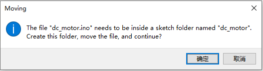
Double-click the .ino main file to open the project. If the pop-up window shown below appears, there is no need to worry. The Wiki resource only provides a standalone .ino file, while the Arduino IDE requires the sketch file to be stored in a folder with the same name. Simply click OK, and the IDE will automatically create a matching folder for normal use.
If the downloaded resource package contains library files in RAR format, there is no need to worry. Extract the file first, then repack it into a ZIP folder, which can be used to add libraries in the IDE. Please kindly notify customer service in a timely manner, and we will revise the file format immediately.
¶ 3.Under what circumstances do you need to install the driver?
- No COM port appears in Device Manager after plugging the ESP32 board into your computer.
No serial port device is displayed, and you cannot select a port to upload firmware in the IDE. - A yellow exclamation mark or question mark shows next to the device under Ports in Device Manager.
The system detects the hardware but lacks a compatible driver, leading to failed uploads and blank serial monitor output. - First-time connection of ESP32 to a Windows PC.
The default Windows serial driver is incompatible with ESP32’s CH340/CP2102 chip, so manual driver installation is mandatory. - Please refer to the following content for relevant links.
Installation of CH340 Serial Port Driver
Installation of CP210X Serial Port Driver
¶ 4.Software Operation Process
- Connect the microcontroller to your computer via a data cable. Open Device Manager, and you will see the corresponding port as shown in the figure below. If no port is displayed or a yellow exclamation mark appears next to the device, download and install the corresponding driver as instructed in Step 3.

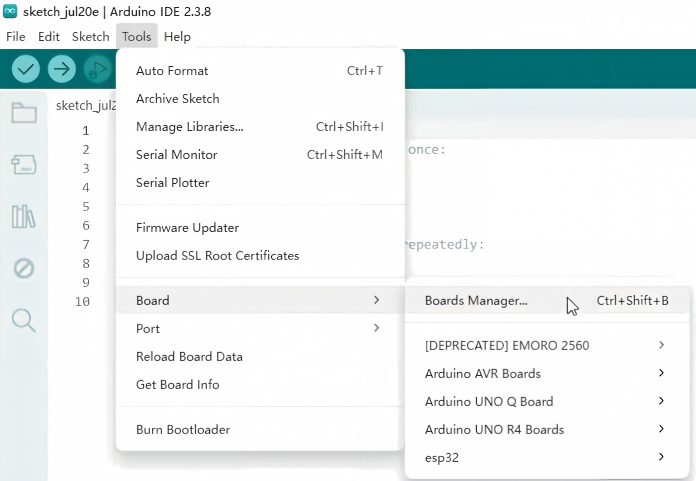
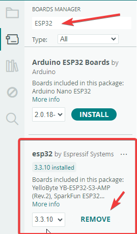
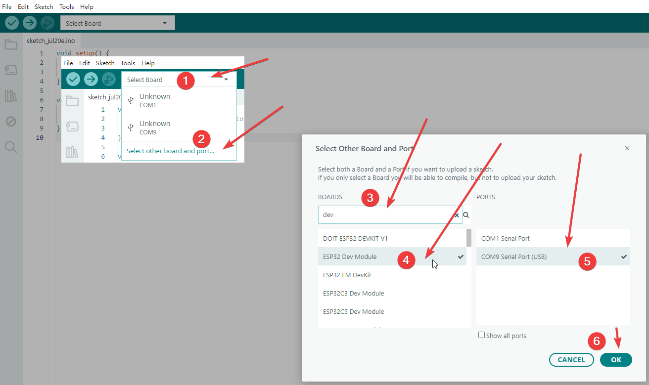
- Connect the development board as shown in the figure and follow the marked numbers step by step. If the corresponding board cannot be found in the software, check the wiring connection or installed drivers.
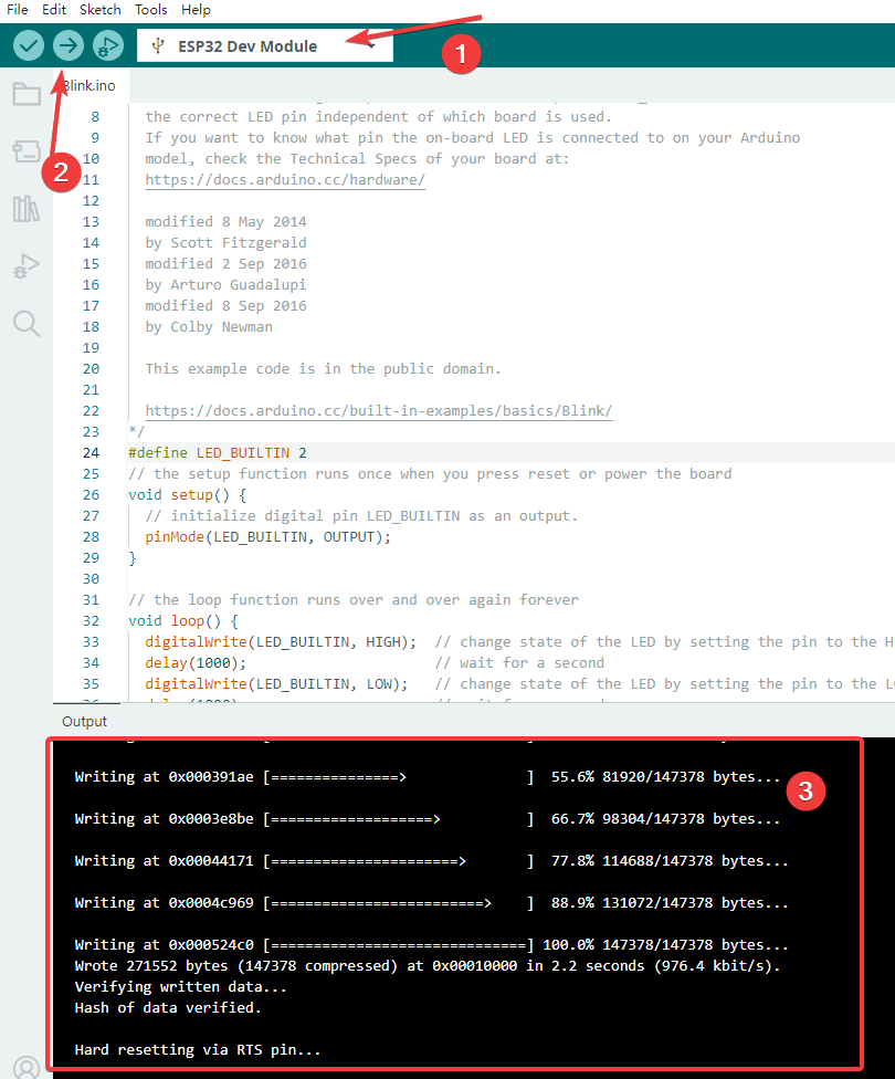
- You can upload the program after connecting the board, refer to the figure below for operations. First check whether the board text at No.1 is bolded black; if not, the connection fails. Then click the compile & upload button marked No.2, the IDE will compile automatically. If no compilation errors occur, the program will be uploaded to the board automatically. Upload progress and logs will be displayed in the bottom output window at No.3.
¶ 5.Errors in programs provided on the Wiki
-
Report the issue directly to customer service. The R&D team will review relevant content promptly and update the Wiki. Please describe the problem in detail when submitting feedback to help support staff provide accurate solutions.
-
Check the code notes on the Wiki page to confirm if you are using the correct version. The R&D team may have uploaded the wrong code version by mistake.
¶ 6. No error prompts after flashing the program, but the expected function fails to work
-
Check if all wiring is connected correctly, especially the positive and negative power wires.
-
Verify whether the physical pins match the pins defined in the code. For example, if the hardware wire is connected to D5 while the code configures pin D8, no error will occur, yet the function still cannot run normally.
¶ 7. Missing library files during compilation
As shown in the figure below, this prompt means the required library files are missing. Do not worry; simply install the corresponding libraries. You may refer to the tutorial at https://wiki.elegoo.com/oshw-getting-started-&-kits/library-Installation, and click the blue text to jump to the page library-Installation.

¶ 8.The code version is too old
Many library developers keep updating and maintaining their libraries, which makes some code from tutorials outdated compared to the latest library versions. This may cause compilation errors or no output after uploading the code. When this issue happens, the serial monitor will usually display the following prompts.
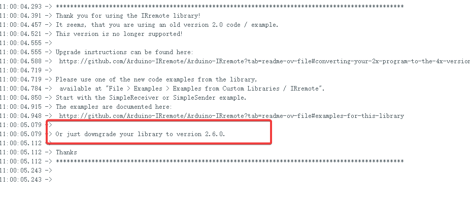
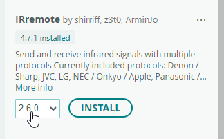
Steps to downgrade library version: Open the Library Manager, search for the target library such as IRremote, select the specified historical version and click install.
¶ 9.Differences between different mainboards and code compatibility
The most obvious differences between different development boards lie in performance and hardware features, followed by pin definitions. Nevertheless, most basic functions are universal. When only working on basic projects, you only need to modify the corresponding pin numbers in the code to achieve compatibility across boards, provided that the basic functions of the pins match. For instance, different boards mark their IIC pins differently. After switching boards, you must connect to the correct hardware IIC pins for the IIC functions to work properly.
¶ 10.Temporary test power supply and stable power supply
Some kits are equipped with batteries and power transfer modules. The circuit diagrams in the tutorials are for demonstration only, so the power transfer module is not shown in some wiring schematics, where only the main board power interface is used for power supply. If the device needs to run continuously for a long time, be sure to use the power transfer module to provide stable voltage and prevent the microcontroller from burning out.
¶ 11.Hardware Wiring and Troubleshooting
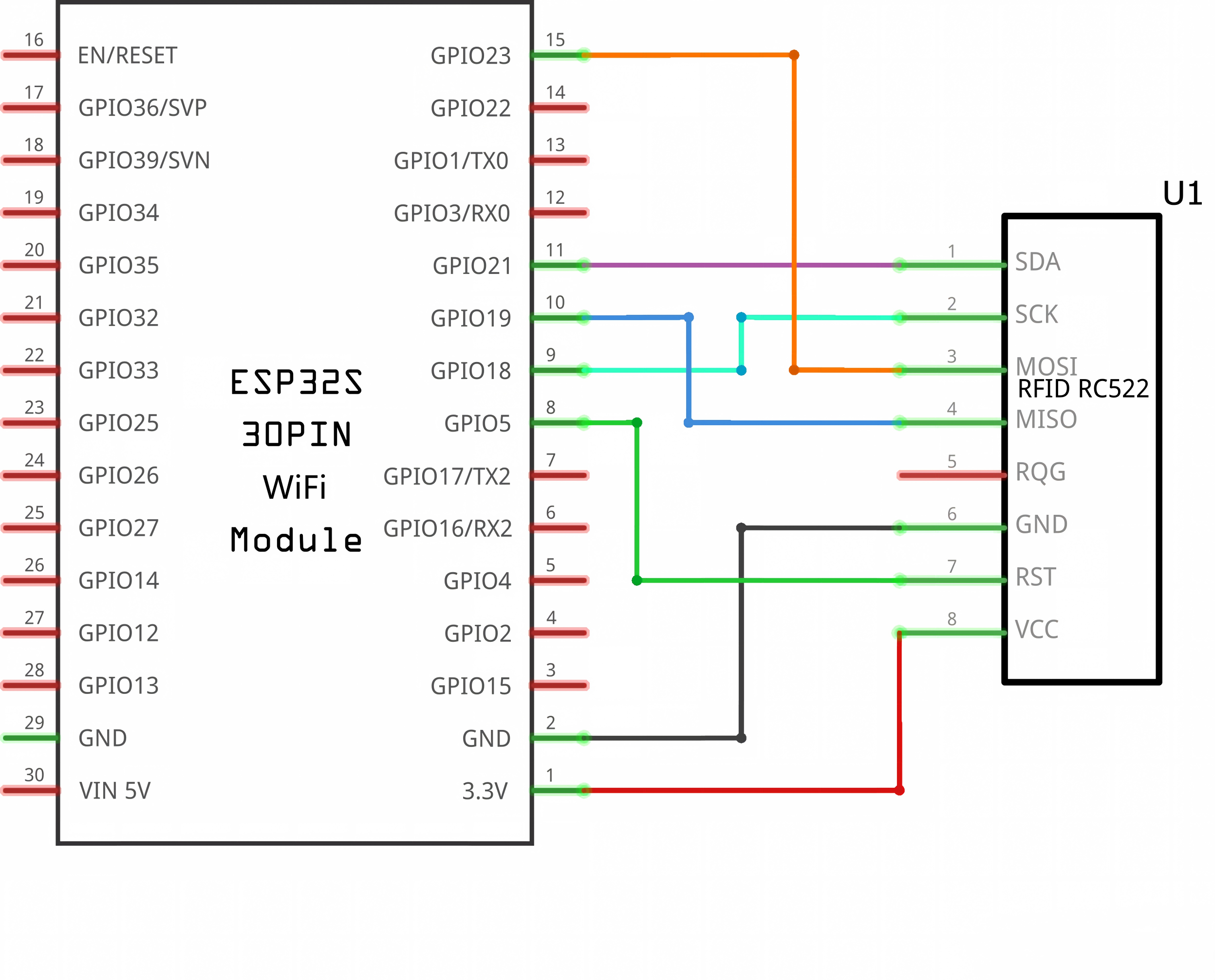
If the problem persists after troubleshooting the program code, check your wiring connections. First verify normal power supply, and check for reversed positive/negative poles or broken circuits. Next inspect data pins. Compare each pin against the schematic and wiring diagram provided in the tutorial as shown below, especially pins with inconsistent labels.