¶ Download and Usage
Powering the Board
The Arduino UNO Q can be powered by:
- A USB-C® cable providing 5 VDC 3 A (not included).
- An external +5 VDC power supply connected to 5V pin.
- An external +7-24 VDC power supply connected to VIN pin.
It is recommended not to power the device with a supply voltage above 12 V, as this carries a high risk. Power supplies over 12 V should only be used for temporary testing. For long‑term operation, please use a power source below 12 V to extend the service life of the hardware.
¶ Install Arduino App Lab
The Arduino App Lab is a unified development environment that extends the classic Arduino experience into the world of high-performance computing. Arduino App Lab lets you seamlessly combine Arduino sketches, Python scripts, and containerized Linux applications into a single workflow.
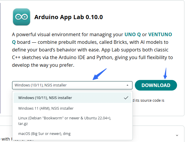
You can click the blue text to jump to the corresponding download page, or visit the link below.
https://docs.arduino.cc/software/app-lab/
Arduino App Lab with code building blocks called Bricks, preconfigured AI models, and integrated orchestration, it reduces complexity while enabling you to create everything from simple prototypes to advanced, computation-intensive applications.
After navigating to the download page, please select and download the version compatible with your computer's operating system.
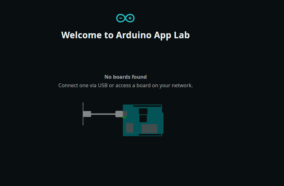
After the download is completed, you will see the interface shown below. You need to connect the UNO‑Q controller board for the update. This process takes a long time. It is recommended to perform the update on a computer, rather than updating inside the UNO‑Q system.
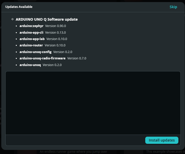
When you first receive the UNO‑Q controller board, it is recommended to perform an update to improve compatibility of libraries and software. After the download and update are finished, you will enter the resource page. You can start with the example programs to get familiar with UNO‑Q programming.
¶ Programming UNO‑Q with the Arduino App Lab
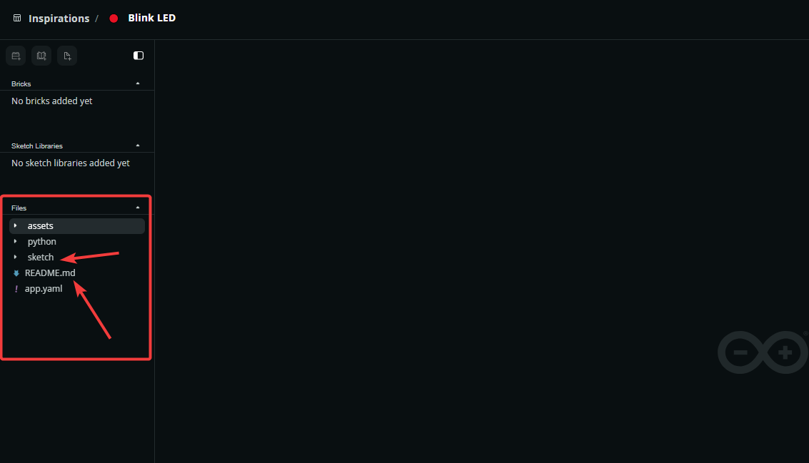
Next, we will take Blink LED as an example. You can click the Inspiration button to find the sample projects, as shown in the figure below.
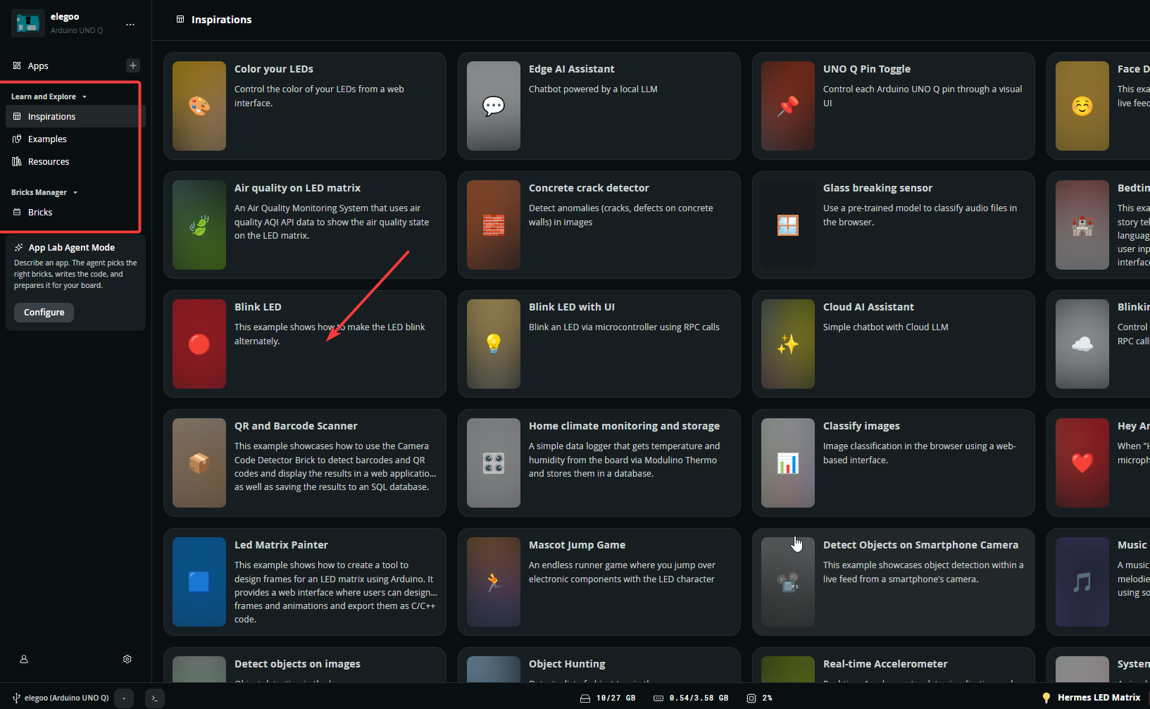
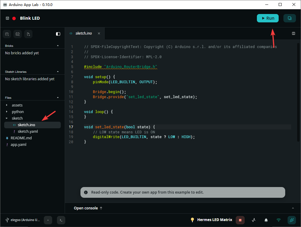
Click Blink LED to enter the corresponding interface. Beginners can first read the README.MD file to learn about the project introduction and basic‑operation instructions. After a brief overview, click Sketch to view the Arduino source code.
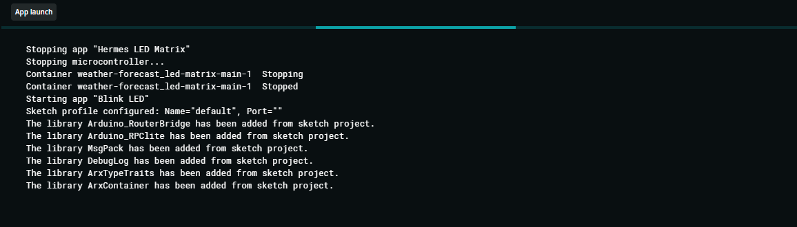
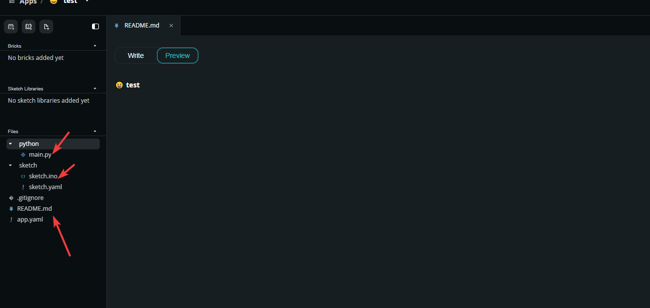
You may also create your own app and write custom programs and documentation. The specific steps are as follows:
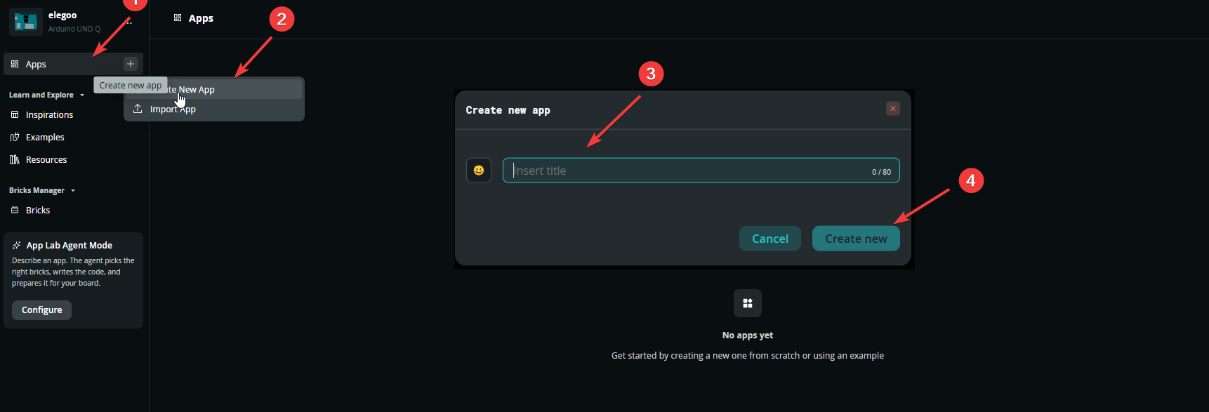
After entering the app name, you will enter the same interface as the Blink app mentioned above. Use readme.md to write descriptions and operating instructions, and use sketch.ino for your Arduino program.
¶ Programming UNO‑Q with the Arduino IDE
If you want to program the UNO‑Q using the Arduino IDE, this is also supported. Please refer to the link below for detailed instructions:
https://wiki.elegoo.com/oshw-getting-started-&-kits/ide-download
Please note that you only need to switch the corresponding core driver to UNO‑Q.
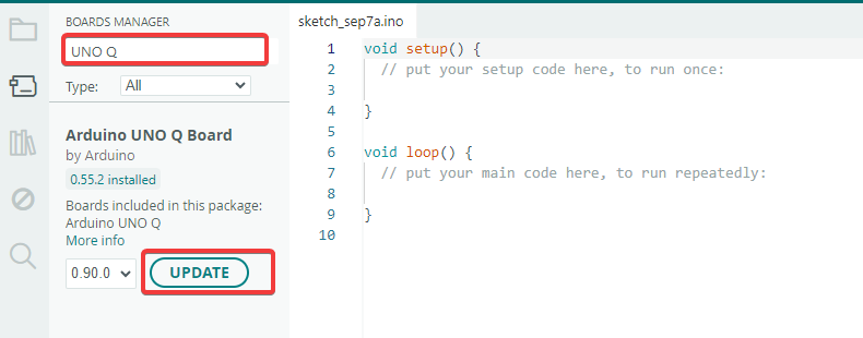
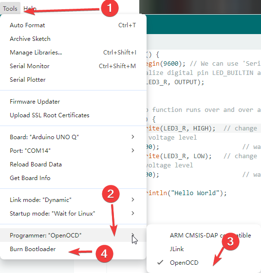
Some boards may suffer from Bootloader failure at factory‑out state or after usage, resulting in uploaded programs failing to run properly. Do not worry, you can update it directly within the IDE. Follow the steps below:
- Connect the USB cable and select the UNO‑Q board
- Navigate to menu
Tools → Programmer → OpenOCD - Click Burn Bootloader
You can try the code below to check whether the red LED can turn on and blink continuously.
void setup() {
  Serial.begin(9600); // We can use 'Serial' again!
  // initialize digital pin LED_BUILTIN as an output.
  pinMode(LED_BUILTIN, OUTPUT);
}

// the loop function runs over and over again forever
void loop() {
  digitalWrite(LED_BUILTIN, HIGH);  // change state of the LED by setting the pin to the HIGH voltage level
  delay(1000);                      // wait for a second
  digitalWrite(LED_BUILTIN, LOW);   // change state of the LED by setting the pin to the LOW voltage level
  delay(1000);                      // wait for a second

  Serial.println("Hello World");
}
There are 4 RGB tri‑color LEDs on the board, driven by two separate cores.
All RGB LEDs are Active‑Low: LOW turns the LED on, HIGH turns it off. This logic is opposite to classic Arduino boards.
❗Pin D13 is no longer mapped to the on‑board LED! The LED_BUILTIN macro does not point to any on‑board LED. D13 works as a general‑purpose I/O only. Copying the UNO‑R3 blink example directly will not light any on‑board LED.
The two cores are isolated from each other: the STM32‑MCU (Arduino Sketch) cannot directly control LEDs belonging to the MPU (Linux), and the MPU cannot directly manipulate LEDs on the MCU side.
These two RGB LEDs labeled STM‑3 and STM‑4 are directly accessible from standard Arduino sketches.
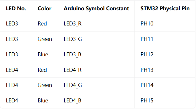
In the code above, you can replace LED_BUILTIN with LED3_R, which will also make the red LED turn on and blink repeatedly.